
Product Specification
Page 7
Supported Intel® Server Boards 74 - 8.1 Intel® Server Board SE7221BK1-E Feature Set 74 - 9. Regulatory, Environmentals, and Specifications...Service 69 - 7.6 Component De-rating 69 - 7.7 Component Life requirement 69 - 7.8 Mean Time Between Failures (MTBF 69 - 7.9 Warranty Period 69 - 7.10 Serviceability...- 69 - 7.11 Power Supply Returned for Repair 69 - 7.12 Modifications / Change Control 70 - 7.13 Power Supply Compliance Overview 70 - 7.14 Power Supplies...Date Coded Serial Numbers 73 - 7.19.7 Power Input Electrical Ratings 73 - 7.19.8 Maximum ...
Supported Intel® Server Boards 74 - 8.1 Intel® Server Board SE7221BK1-E Feature Set 74 - 9. Regulatory, Environmentals, and Specifications...Service 69 - 7.6 Component De-rating 69 - 7.7 Component Life requirement 69 - 7.8 Mean Time Between Failures (MTBF 69 - 7.9 Warranty Period 69 - 7.10 Serviceability...- 69 - 7.11 Power Supply Returned for Repair 69 - 7.12 Modifications / Change Control 70 - 7.13 Power Supply Compliance Overview 70 - 7.14 Power Supplies...Date Coded Serial Numbers 73 - 7.19.7 Power Input Electrical Ratings 73 - 7.19.8 Maximum ...

Product Specification
Page 9
... PCI-Express Riser Card Mechanical Drawing 49 Figure 34. Front Bezel Options 19 Figure 9. Optional Floppy Drive Configuration 25 Figure 17. SATA Backplane Layout 37 Figure 25. Intel® Server Chassis SC1400UP System Fans 4, 5, 6, 7, 8 21 Figure 11. Revision 1.0 ix Intel® Server Platform SE7221BK1-E System Fan headers 4, 5, 6, 7, 8 21 Figure 12. Major Chassis Components 14 Figure 3. Control Panel Buttons 42 Figure 31. Intel® Server Chassis SC1400UP 1U SATA HSBP I2C Bus Connection Diagram...
... PCI-Express Riser Card Mechanical Drawing 49 Figure 34. Front Bezel Options 19 Figure 9. Optional Floppy Drive Configuration 25 Figure 17. SATA Backplane Layout 37 Figure 25. Intel® Server Chassis SC1400UP System Fans 4, 5, 6, 7, 8 21 Figure 11. Revision 1.0 ix Intel® Server Platform SE7221BK1-E System Fan headers 4, 5, 6, 7, 8 21 Figure 12. Major Chassis Components 14 Figure 3. Control Panel Buttons 42 Figure 31. Intel® Server Chassis SC1400UP 1U SATA HSBP I2C Bus Connection Diagram...

Product Specification
Page 14
Major Chassis Components Revision 1.0 - 14 - Intel® Server Chassis SC1400UP / Intel® Server Platform SR1425BK1-E 1.3 Intel® Server Chassis SC1400UP System Components A Power supply B Chassis Intrusion Switch C Full length PCI Add in card slot D PCI Riser Card Assembly Placement E System Fan Module F CPU Air Duct Placement G Control Panel H Hard Drive Bays I Chassis Handle J Slim Line Drive Bay K PS / Electronics Bay Isolation Air Baffle L Power Supply Fans Figure 2.
Major Chassis Components Revision 1.0 - 14 - Intel® Server Chassis SC1400UP / Intel® Server Platform SR1425BK1-E 1.3 Intel® Server Chassis SC1400UP System Components A Power supply B Chassis Intrusion Switch C Full length PCI Add in card slot D PCI Riser Card Assembly Placement E System Fan Module F CPU Air Duct Placement G Control Panel H Hard Drive Bays I Chassis Handle J Slim Line Drive Bay K PS / Electronics Bay Isolation Air Baffle L Power Supply Fans Figure 2.

Product Specification
Page 15
... keyboard connector B PS2 mouse connector C Serial port A connector (DB9) D Video connector E NIC 2 connector (RJ45) F USB 1 connector G USB 2 connector H NIC 1 connector (RJ45) I /O shield is available to convert the first 1" hard drive bay to a floppy drive bay. Reference Intel Server Chassis SR1400 for all external I /O connector locations are required, on the server board. If both a CDROM or DVD/CDR and Floppy drive are pre-cut, so the use of an I PCI card bracket (full-height) J Rear chassis venting holes K Power Supply fans L AC Power Receptacle Figure 3. Back Panel...
... keyboard connector B PS2 mouse connector C Serial port A connector (DB9) D Video connector E NIC 2 connector (RJ45) F USB 1 connector G USB 2 connector H NIC 1 connector (RJ45) I /O shield is available to convert the first 1" hard drive bay to a floppy drive bay. Reference Intel Server Chassis SR1400 for all external I /O connector locations are required, on the server board. If both a CDROM or DVD/CDR and Floppy drive are pre-cut, so the use of an I PCI card bracket (full-height) J Rear chassis venting holes K Power Supply fans L AC Power Receptacle Figure 3. Back Panel...

Product Specification
Page 17
... addition of Server Management Software, the power subsystem is capable of the control panel. Intel® Server Chassis SC1400UP / Intel® Server Platform SR1425BK1-E The control panel supports several push buttons and status LEDs, along with USB and video ports to centralize system control, monitoring, and accessibility to within the following diagram overviews the layout and functions of supporting several system management features including: • Remote Power On/Off • Status Alerting • FRU Information Reporting The power supply operates within a common...
... addition of Server Management Software, the power subsystem is capable of the control panel. Intel® Server Chassis SC1400UP / Intel® Server Platform SR1425BK1-E The control panel supports several push buttons and status LEDs, along with USB and video ports to centralize system control, monitoring, and accessibility to within the following diagram overviews the layout and functions of supporting several system management features including: • Remote Power On/Off • Status Alerting • FRU Information Reporting The power supply operates within a common...
Product Specification
Page 18
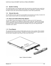
... that use either a Standard Control Panel or Intel Local Control Panel. Separate front bezels are available to support systems that is made of molded plastic and uses a snap-on design. Intel® Server Chassis SC1400UP / Intel® Server Platform SR1425BK1-E 1.8 System Cooling The chassis provides a non-redundant system fans and dual non-redundant power supply fans to provide sufficient air flow for cabled and hot-swap drive configurations, processors, memory and add-in cards, when external ambient...
... that use either a Standard Control Panel or Intel Local Control Panel. Separate front bezels are available to support systems that is made of molded plastic and uses a snap-on design. Intel® Server Chassis SC1400UP / Intel® Server Platform SR1425BK1-E 1.8 System Cooling The chassis provides a non-redundant system fans and dual non-redundant power supply fans to provide sufficient air flow for cabled and hot-swap drive configurations, processors, memory and add-in cards, when external ambient...

Product Specification
Page 21
... memory components on the Intel Server Board SE7221BK1-E. Figure 10. Each dual rotor fan has an 8-pin wire harness which provide the primary airflow for ease of installation and serviceability of the server chassis cooling subsystem. The server must be replaced. Intel® Server Chassis SC1400UP / Intel® Server Platform SR1425BK1-E 2.1 System Fans The Intel® Server Chassis SC1400UP system fans consist of four 40x40x56mm dual rotor and one 40x40x28mm single rotor multi-speed fans, which connects...
... memory components on the Intel Server Board SE7221BK1-E. Figure 10. Each dual rotor fan has an 8-pin wire harness which provide the primary airflow for ease of installation and serviceability of the server chassis cooling subsystem. The server must be replaced. Intel® Server Chassis SC1400UP / Intel® Server Platform SR1425BK1-E 2.1 System Fans The Intel® Server Chassis SC1400UP system fans consist of four 40x40x56mm dual rotor and one 40x40x28mm single rotor multi-speed fans, which connects...

Product Specification
Page 22
... edge of a CPU/Memory air duct and power supply / electronics bay isolation air baffle to have the fan replaced. Intel® Server Chassis SC1400UP / Intel® Server Platform SR1425BK1-E The following table provides the pin-outs for each dual rotor fan header. The system fans are responsible for all the fans within the module is used to the baseboard system fan header #4 (JP5J2). Air Baffle The CPU/Memory air duct must...
... edge of a CPU/Memory air duct and power supply / electronics bay isolation air baffle to have the fan replaced. Intel® Server Chassis SC1400UP / Intel® Server Platform SR1425BK1-E The following table provides the pin-outs for each dual rotor fan header. The system fans are responsible for all the fans within the module is used to the baseboard system fan header #4 (JP5J2). Air Baffle The CPU/Memory air duct must...

Product Specification
Page 23
... order to support either a single or dual processor configuration. Figure 13. Hard drive trays, both hot-swap and cabled drive, must be populated in order to maintain system thermals. For dual processor configurations, the air damn must ether have a hard drive or drive blank installed in degraded performance as a result of throttling or thermal shutdown of the CPU air duct. Intel® Server Chassis SC1400UP / Intel® Server Platform SR1425BK1-E designed to...
... order to support either a single or dual processor configuration. Figure 13. Hard drive trays, both hot-swap and cabled drive, must be populated in order to maintain system thermals. For dual processor configurations, the air damn must ether have a hard drive or drive blank installed in degraded performance as a result of throttling or thermal shutdown of the CPU air duct. Intel® Server Chassis SC1400UP / Intel® Server Platform SR1425BK1-E designed to...

Product Specification
Page 24
... Configuration Options 3.1 Slimline Drive Bay The chassis provides a slim-line drive bay that can support cabled SATA drive configurations. View of Slim-Line Drive Bay 3.1.1 Floppy Drive Support with or without the presence of a backplane. the first has 28 pins which is cabled directly to support both SCSI and SATA hot-swap backplanes or can be configured for easy installation into and removal from the power supply. Intel® Server Chassis SC1400UP / Intel® Server Platform SR1425BK1...
... Configuration Options 3.1 Slimline Drive Bay The chassis provides a slim-line drive bay that can support cabled SATA drive configurations. View of Slim-Line Drive Bay 3.1.1 Floppy Drive Support with or without the presence of a backplane. the first has 28 pins which is cabled directly to support both SCSI and SATA hot-swap backplanes or can be configured for easy installation into and removal from the power supply. Intel® Server Chassis SC1400UP / Intel® Server Platform SR1425BK1...

Product Specification
Page 28
... chassis. E A B C D OM11684 Figure 17. Each drive tray supports a light pipe providing a drive status indicator, located on the controller used in place. Note: Depending on the backplane, to be viewable from the chassis and lock the tray in a hard drive bay. Hard Drive Tray Assembly A. Intel® Server Chassis SC1400UP / Intel® Server Platform SR1425BK1-E 3.2.1 Hot Swap Hard Disk Drive Trays In a hot swap configuration, each SATA/SCSI hard drive must be mounted to a non...
... chassis. E A B C D OM11684 Figure 17. Each drive tray supports a light pipe providing a drive status indicator, located on the controller used in place. Note: Depending on the backplane, to be viewable from the chassis and lock the tray in a hard drive bay. Hard Drive Tray Assembly A. Intel® Server Chassis SC1400UP / Intel® Server Platform SR1425BK1-E 3.2.1 Hot Swap Hard Disk Drive Trays In a hot swap configuration, each SATA/SCSI hard drive must be mounted to a non...
Product Specification
Page 29
...) supports the following diagram shows the layout of major components and connectors of the board. SPI-4 compatible ƒ Temperature Sensor ƒ Hard Drive Status LEDs ƒ FRU EEPROM ƒ One 2x3-pin Power Connector ƒ IDE Connector provided for Slim-line CDROM or DVD support ƒ Floppy Connector provided for up to three U320 LVD SCSI Drives o Onboard LVD SCSI Termination - Intel® Server Chassis SC1400UP / Intel® Server Platform SR1425BK1-E Figure...
...) supports the following diagram shows the layout of major components and connectors of the board. SPI-4 compatible ƒ Temperature Sensor ƒ Hard Drive Status LEDs ƒ FRU EEPROM ƒ One 2x3-pin Power Connector ƒ IDE Connector provided for Slim-line CDROM or DVD support ƒ Floppy Connector provided for up to three U320 LVD SCSI Drives o Onboard LVD SCSI Termination - Intel® Server Chassis SC1400UP / Intel® Server Platform SR1425BK1-E Figure...

Product Specification
Page 30
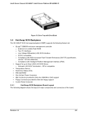
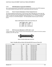
... Backplane Layout Control Panel Connector not used in SR1425BK1 3.3.2 SCSI Backplane Functional Architecture This section provides a high-level description of the functionality distributed between the architectural blocks of the hot-swap SCSI backplane. Intel® Server Chassis SC1400UP / Intel® Server Platform SR1425BK1-E Power Connector SCSI Connector to SCSI add-in card 100pin connector not used in SR1425BK1 Floppy Drive Connector not used in SR1425BK1 Thumb Screw IDE Connector not used in SR1425BK1 SCA2 SCSI Hard Drive Connectors Drive Status LEDs Figure...
... Backplane Layout Control Panel Connector not used in SR1425BK1 3.3.2 SCSI Backplane Functional Architecture This section provides a high-level description of the functionality distributed between the architectural blocks of the hot-swap SCSI backplane. Intel® Server Chassis SC1400UP / Intel® Server Platform SR1425BK1-E Power Connector SCSI Connector to SCSI add-in card 100pin connector not used in SR1425BK1 Floppy Drive Connector not used in SR1425BK1 Thumb Screw IDE Connector not used in SR1425BK1 SCA2 SCSI Hard Drive Connectors Drive Status LEDs Figure...
Product Specification
Page 31
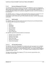
... the baseboard. Also supported is supported through I2C port 1. The I2C core incorporates 8-bit FIFOs for drive detection and power controller enable/disable functionality. 3.3.2.1.1 SCSI Interface The GEM359 supports LVD SCSI operation through 8-bit asynchronous SCSI data transfers. Intel® Server Chassis SC1400UP / Intel® Server Platform SR1425BK1-E 3.3.2.1 Enclosure Management Controller The SCSI backplane utilizes the features of the QLogic® GEM359 for enclosure management which are used for data transfer...
... the baseboard. Also supported is supported through I2C port 1. The I2C core incorporates 8-bit FIFOs for drive detection and power controller enable/disable functionality. 3.3.2.1.1 SCSI Interface The GEM359 supports LVD SCSI operation through 8-bit asynchronous SCSI data transfers. Intel® Server Chassis SC1400UP / Intel® Server Platform SR1425BK1-E 3.3.2.1 Enclosure Management Controller The SCSI backplane utilizes the features of the QLogic® GEM359 for enclosure management which are used for data transfer...
Product Specification
Page 33
... each connector. 3.3.3.1 Power Connector (Backplane to Power Supply Harness) The SCSI backplane provides power to the three drive bays supporting up to interface the SCSI backplane with an add-in card) A 68-pin SCSI cable is routed from the power distribution board and plugs into a 2 x 3 shrouded plastic PC power connector on the SCSI backplane. A 6-pin power cable is used to three hard disk drives and the slim-line drive bay supporting one floppy drive or CD-ROM drive. Figure...
... each connector. 3.3.3.1 Power Connector (Backplane to Power Supply Harness) The SCSI backplane provides power to the three drive bays supporting up to interface the SCSI backplane with an add-in card) A 68-pin SCSI cable is routed from the power distribution board and plugs into a 2 x 3 shrouded plastic PC power connector on the SCSI backplane. A 6-pin power cable is used to three hard disk drives and the slim-line drive bay supporting one floppy drive or CD-ROM drive. Figure...

Product Specification
Page 44
...% duty cycle. 2. The operating system has saved context and gone into a level of the following status conditions may or may not be restored when the system is still on , but the BIOS has not yet initialized the chipset. Refer to the hard disk. Blink rate is on . Notes: 1. Intel® Server Chassis SC1400UP / Intel® Server Platform SR1425BK1-E LED Color State Description Green...
...% duty cycle. 2. The operating system has saved context and gone into a level of the following status conditions may or may not be restored when the system is still on , but the BIOS has not yet initialized the chipset. Refer to the hard disk. Blink rate is on . Notes: 1. Intel® Server Chassis SC1400UP / Intel® Server Platform SR1425BK1-E LED Color State Description Green...

Product Specification
Page 45
... remotely through server management software. Intel® Server Chassis SC1400UP / Intel® Server Platform SR1425BK1-E 4.2.2.1 Critical Conditions A critical condition is any critical or non-recoverable threshold crossing associated with the following events: • Temperature, voltage, or fan critical threshold crossing. • Power subsystem failure. The server board SE7221BK1-E also provides a header giving access to indicate when one or more processors are asserted on the control panel is unable to power...
... remotely through server management software. Intel® Server Chassis SC1400UP / Intel® Server Platform SR1425BK1-E 4.2.2.1 Critical Conditions A critical condition is any critical or non-recoverable threshold crossing associated with the following events: • Temperature, voltage, or fan critical threshold crossing. • Power subsystem failure. The server board SE7221BK1-E also provides a header giving access to indicate when one or more processors are asserted on the control panel is unable to power...

Product Specification
Page 73
Revision 1.0 - 73 - Intel® Server Chassis SC1400UP / Intel® Server Platform SR1425BK1-E required, it shall be placed in such a manner that when the power supply is extracted from the system, the label shall be visible before the operator has a chance to touch the hot surface of the power supply. 7.19.6 Date Coded Serial Numbers Power supply shall be marked with a date-coded number for traceability purposes and to comply...
Revision 1.0 - 73 - Intel® Server Chassis SC1400UP / Intel® Server Platform SR1425BK1-E required, it shall be placed in such a manner that when the power supply is extracted from the system, the label shall be visible before the operator has a chance to touch the hot surface of the power supply. 7.19.6 Date Coded Serial Numbers Power supply shall be marked with a date-coded number for traceability purposes and to comply...
Product Specification
Page 74
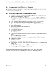
... number and is capable of the Server Board SE7221BK1-E. Intel® Server Chassis SC1400UP / Intel® Server Platform SR1425BK1-E 8. This slot is identified in the first 20 pins • Intel® Light-Guided Diagnostics on all FRU devices (processors, memory, power) • Port-80 Diagnostic LEDs displaying POST codes The following image shows the board layout of supporting full height/full length PCI-X 66/100/133 or x8 PCI-Express adapters. • Four DIMM slots supporting DDR2 - 400/533MHz Un-buffered ECC memory • Dual Intel...
... number and is capable of the Server Board SE7221BK1-E. Intel® Server Chassis SC1400UP / Intel® Server Platform SR1425BK1-E 8. This slot is identified in the first 20 pins • Intel® Light-Guided Diagnostics on all FRU devices (processors, memory, power) • Port-80 Diagnostic LEDs displaying POST codes The following image shows the board layout of supporting full height/full length PCI-X 66/100/133 or x8 PCI-Express adapters. • Four DIMM slots supporting DDR2 - 400/533MHz Un-buffered ECC memory • Dual Intel...

Product Specification
Page 80
... replace hard disk drive Remove and replace power supply module Remove and replace system fan Remove and replace backplane board Remove and replace front panel board Remove and replace baseboard Time Estimate 10 sec 3 min1 2 min 2 min 5 min 5 min 10 min 1 Includes swapping drive from drive ray Revision 1.0 - 80 - Table 46. Following are the maximum times that a trained field service technician should take to minimize the MTTR. Intel® Server Chassis SC1400UP / Intel® Server Platform SR1425BK1-E Parameter Shock, operating...
... replace hard disk drive Remove and replace power supply module Remove and replace system fan Remove and replace backplane board Remove and replace front panel board Remove and replace baseboard Time Estimate 10 sec 3 min1 2 min 2 min 5 min 5 min 10 min 1 Includes swapping drive from drive ray Revision 1.0 - 80 - Table 46. Following are the maximum times that a trained field service technician should take to minimize the MTTR. Intel® Server Chassis SC1400UP / Intel® Server Platform SR1425BK1-E Parameter Shock, operating...


