
Product Specification
Page 1
Intel® Server Chassis SC1400UP / Intel® Server Platform SR1425BK1-E Technical Product Specification Intel order number C94051-001 Revision 1.0 October 2004 Enterprise Platforms and Services Marketing
Intel® Server Chassis SC1400UP / Intel® Server Platform SR1425BK1-E Technical Product Specification Intel order number C94051-001 Revision 1.0 October 2004 Enterprise Platforms and Services Marketing

Product Specification
Page 3
.... Disclaimers Information in this document is provided in connection with this information. Do not finalize a design with Intel® products. The Intel® Server Chassis SC1400UP and Intel® Server Platform SR1425BK1-E may contain design defects or errors known as the property of any features or instructions marked "reserved" or "undefined." This document and the software described...
.... Disclaimers Information in this document is provided in connection with this information. Do not finalize a design with Intel® products. The Intel® Server Chassis SC1400UP and Intel® Server Platform SR1425BK1-E may contain design defects or errors known as the property of any features or instructions marked "reserved" or "undefined." This document and the software described...

Product Specification
Page 4
... SC1400UP Feature Summary 13 - 1.1 Chassis Views 13 - 1.2 Chassis Dimensions 13 - 1.3 Intel® Server Chassis SC1400UP System Components 14 - 1.4 Rear Panel Components 15 - 1.5 Hard Drive and Peripheral Bays 15 - 1.6 Control Panel ...- 16 - 1.7 Power Sub-system 17 - 1.8 System Cooling 18 - 1.9 ...
... SC1400UP Feature Summary 13 - 1.1 Chassis Views 13 - 1.2 Chassis Dimensions 13 - 1.3 Intel® Server Chassis SC1400UP System Components 14 - 1.4 Rear Panel Components 15 - 1.5 Hard Drive and Peripheral Bays 15 - 1.6 Control Panel ...- 16 - 1.7 Power Sub-system 17 - 1.8 System Cooling 18 - 1.9 ...

Product Specification
Page 7
Supported Intel® Server Boards 74 - 8.1 Intel® Server Board SE7221BK1-E Feature Set 74 - 9. Regulatory, Environmentals, and Specifications 76 - 9.1 Product Regulatory Compliance 76 - 9.1.1 Product Safety Compliance 76 - 9.1.2 Product EMC Compliance 76 - 9.1.3 Product Regulatory Compliance ...
Supported Intel® Server Boards 74 - 8.1 Intel® Server Board SE7221BK1-E Feature Set 74 - 9. Regulatory, Environmentals, and Specifications 76 - 9.1 Product Regulatory Compliance 76 - 9.1.1 Product Safety Compliance 76 - 9.1.2 Product EMC Compliance 76 - 9.1.3 Product Regulatory Compliance ...

Product Specification
Page 8
Appendix A: Intel® Server Chassis SC1400UP Integration and Usage Tips I Glossary...II Revision 1.0 viii 9.2.5 Japan EMC Compatibility 78 - 9.2.6 BSMI (Taiwan 78 - 9.3 Replacing the Back up Battery 78 - 9.4 System Level Environmental Limits 79 - 9.5 Serviceability...- 80 -
Appendix A: Intel® Server Chassis SC1400UP Integration and Usage Tips I Glossary...II Revision 1.0 viii 9.2.5 Japan EMC Compatibility 78 - 9.2.6 BSMI (Taiwan 78 - 9.3 Replacing the Back up Battery 78 - 9.4 System Level Environmental Limits 79 - 9.5 Serviceability...- 80 -

Product Specification
Page 9
...Drive Configuration 25 Figure 17. Hot-Swap SCSI Backplane Functional Diagram 30 Figure 21. SATA Backplane Layout 37 Figure 26. Intel® Server Chassis SC1400UP 1U SATA HSBP I2C Bus Connection Diagram- 39 Figure 28. Standard Control Panel Overview 17 Figure 7. Front Bezel...ix Optional Front Bezel 18 Figure 8. SATA Backplane Layout 37 Figure 25. Intel® Server Platform SE7221BK1-E System Fan headers 4, 5, 6, 7, 8 21 Figure 12. Hot-Swap SCSI Backplane Layout 30 Figure 20. Intel® Server Chassis SC1400UP 1U SCSI HSBP I2C Bus Connection Diagram- 32 Figure 22. ...
...Drive Configuration 25 Figure 17. Hot-Swap SCSI Backplane Functional Diagram 30 Figure 21. SATA Backplane Layout 37 Figure 26. Intel® Server Chassis SC1400UP 1U SATA HSBP I2C Bus Connection Diagram- 39 Figure 28. Standard Control Panel Overview 17 Figure 7. Front Bezel...ix Optional Front Bezel 18 Figure 8. SATA Backplane Layout 37 Figure 25. Intel® Server Platform SE7221BK1-E System Fan headers 4, 5, 6, 7, 8 21 Figure 12. Hot-Swap SCSI Backplane Layout 30 Figure 20. Intel® Server Chassis SC1400UP 1U SCSI HSBP I2C Bus Connection Diagram- 32 Figure 22. ...
Product Specification
Page 13
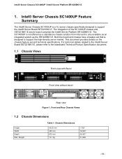
... view Figure 1. The integration of the SC1400UP chassis and SE7221BK1-E server board comprise the Intel® Server Platform SR1425BK1-E. Front and Rear Chassis Views 1.2 Chassis Dimensions Height Width Depth Max. For technical details related to the Intel® Server Board SE7221BK1-E, please refer to support the Intel® Server Board SE7221BK1-E. Chassis Dimensions 43.25 mm 430 mm 672...
... view Figure 1. The integration of the SC1400UP chassis and SE7221BK1-E server board comprise the Intel® Server Platform SR1425BK1-E. Front and Rear Chassis Views 1.2 Chassis Dimensions Height Width Depth Max. For technical details related to the Intel® Server Board SE7221BK1-E, please refer to support the Intel® Server Board SE7221BK1-E. Chassis Dimensions 43.25 mm 430 mm 672...

Product Specification
Page 14
Major Chassis Components Revision 1.0 - 14 - Intel® Server Chassis SC1400UP / Intel® Server Platform SR1425BK1-E 1.3 Intel® Server Chassis SC1400UP System Components A Power supply B Chassis Intrusion Switch C Full length PCI Add in card slot D PCI Riser Card Assembly Placement E System Fan Module F CPU Air Duct Placement G Control Panel H Hard Drive Bays I Chassis Handle J Slim Line Drive Bay K PS / Electronics Bay Isolation Air Baffle L Power Supply Fans Figure 2.
Major Chassis Components Revision 1.0 - 14 - Intel® Server Chassis SC1400UP / Intel® Server Platform SR1425BK1-E 1.3 Intel® Server Chassis SC1400UP System Components A Power supply B Chassis Intrusion Switch C Full length PCI Add in card slot D PCI Riser Card Assembly Placement E System Fan Module F CPU Air Duct Placement G Control Panel H Hard Drive Bays I Chassis Handle J Slim Line Drive Bay K PS / Electronics Bay Isolation Air Baffle L Power Supply Fans Figure 2.

Product Specification
Page 15
Intel® Server Chassis SC1400UP / Intel® Server Platform SR1425BK1-E 1.4 Rear Panel Components On the back of the following slim-line devices: CDROM drive, DVD Drive, DVD/CDR Drive, or Floppy drive. The ... 1 connector (RJ45) I /O shield is designed to support up to support several different hard drive and peripheral configurations. Reference Intel Server Chassis SR1400 for all external I /O connector locations are required, on the server board. SATA and SCSI hot-swap configurations require an orderable accessory kit which includes the necessary cables, drive trays and...
Intel® Server Chassis SC1400UP / Intel® Server Platform SR1425BK1-E 1.4 Rear Panel Components On the back of the following slim-line devices: CDROM drive, DVD Drive, DVD/CDR Drive, or Floppy drive. The ... 1 connector (RJ45) I /O shield is designed to support up to support several different hard drive and peripheral configurations. Reference Intel Server Chassis SR1400 for all external I /O connector locations are required, on the server board. SATA and SCSI hot-swap configurations require an orderable accessory kit which includes the necessary cables, drive trays and...

Product Specification
Page 16
Front Panel Feature Overview A Slim-line drive bay (CDROM or DVD/CDR or Floppy) B Control Panel C Hard Drive Fault/Activity LED D 1" Hard Drive Bays E Chassis Handle 1.6 Control Panel The Server Chassis SC1400UP control panel assembly is pre-assembled and modular in the front of the chassis. The entire module assembly slides into a predefined slot in design. Revision 1.0 Figure 5. Control Panel Module - 16 - Intel® Server Chassis SC1400UP / Intel® Server Platform SR1425BK1-E Figure 4.
Front Panel Feature Overview A Slim-line drive bay (CDROM or DVD/CDR or Floppy) B Control Panel C Hard Drive Fault/Activity LED D 1" Hard Drive Bays E Chassis Handle 1.6 Control Panel The Server Chassis SC1400UP control panel assembly is pre-assembled and modular in the front of the chassis. The entire module assembly slides into a predefined slot in design. Revision 1.0 Figure 5. Control Panel Module - 16 - Intel® Server Chassis SC1400UP / Intel® Server Platform SR1425BK1-E Figure 4.

Product Specification
Page 17
...: • Status LED • Over temperature protection circuitry • Over voltage protection circuitry With the addition of Server Management Software, the power subsystem is capable of the control panel. Intel® Server Chassis SC1400UP / Intel® Server Platform SR1425BK1-E The control panel supports several system management features including: • Remote Power On/Off • Status Alerting •...
...: • Status LED • Over temperature protection circuitry • Over voltage protection circuitry With the addition of Server Management Software, the power subsystem is capable of the control panel. Intel® Server Chassis SC1400UP / Intel® Server Platform SR1425BK1-E The control panel supports several system management features including: • Remote Power On/Off • Status Alerting •...
Product Specification
Page 18
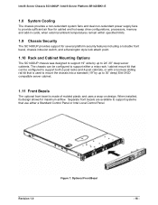
Revision 1.0 Figure 7. Intel® Server Chassis SC1400UP / Intel® Server Platform SR1425BK1-E 1.8 System Cooling The chassis provides a non-redundant system fans and dual non-redundant power supply fans to provide sufficient air flow ...within specified limits. 1.9 Chassis Security The SC1400UP provides support for maximum airflow. Optional Front Bezel - 18 - When installed, its design allows for several platform security features including a lockable front bezel, chassis intrusion switch, and a Kensington style lock attach point. 1.10 Rack and Cabinet Mounting Options The SC1400UP...
Revision 1.0 Figure 7. Intel® Server Chassis SC1400UP / Intel® Server Platform SR1425BK1-E 1.8 System Cooling The chassis provides a non-redundant system fans and dual non-redundant power supply fans to provide sufficient air flow ...within specified limits. 1.9 Chassis Security The SC1400UP provides support for maximum airflow. Optional Front Bezel - 18 - When installed, its design allows for several platform security features including a lockable front bezel, chassis intrusion switch, and a Kensington style lock attach point. 1.10 Rack and Cabinet Mounting Options The SC1400UP...

Product Specification
Page 19
Intel® Server Chassis SC1400UP / Intel® Server Platform SR1425BK1-E Light pipes in the front bezel supporting the Standard Control Panel allow the system status LEDs to be monitored with the bezel installed Figure 8. Front Bezel Options Revision 1.0 - 19 -
Intel® Server Chassis SC1400UP / Intel® Server Platform SR1425BK1-E Light pipes in the front bezel supporting the Standard Control Panel allow the system status LEDs to be monitored with the bezel installed Figure 8. Front Bezel Options Revision 1.0 - 19 -

Product Specification
Page 20
Note: The Server Chassis SC1400UP does not support redundant cooling. Should a fan fail, the system should be properly installed... the system, the air baffle, CPU/Memory air duct, and the top cover need to be brought down as soon as possible to the system. Intel® Server Chassis SC1400UP Cooling Subsystem A System Fan #4 D Air Baffle B Fans 5, 6, 7, 8 E CPU Heat Sink C CPU / Memory Air Duct Revision...Bay Isolation Air Baffle, to provide the necessary cooling and airflow to replace the failed fan. Intel® Server Chassis SC1400UP / Intel® Server Platform SR1425BK1-E 2.
Note: The Server Chassis SC1400UP does not support redundant cooling. Should a fan fail, the system should be properly installed... the system, the air baffle, CPU/Memory air duct, and the top cover need to be brought down as soon as possible to the system. Intel® Server Chassis SC1400UP Cooling Subsystem A System Fan #4 D Air Baffle B Fans 5, 6, 7, 8 E CPU Heat Sink C CPU / Memory Air Duct Revision...Bay Isolation Air Baffle, to provide the necessary cooling and airflow to replace the failed fan. Intel® Server Chassis SC1400UP / Intel® Server Platform SR1425BK1-E 2.

Product Specification
Page 21
... connector which connects to right, in cards, the ICH6R and PXH chipset components. Intel® Server Platform SE7221BK1-E System Fan headers 4, 5, 6, 7, 8 Revision 1.0 - 21 - The individual fans are shown, from the baseboard. Intel® Server Chassis SC1400UP / Intel® Server Platform SR1425BK1-E 2.1 System Fans The Intel® Server Chassis SC1400UP system fans consist of four 40x40x56mm dual rotor and one 40x40x28mm single...
... connector which connects to right, in cards, the ICH6R and PXH chipset components. Intel® Server Platform SE7221BK1-E System Fan headers 4, 5, 6, 7, 8 Revision 1.0 - 21 - The individual fans are shown, from the baseboard. Intel® Server Chassis SC1400UP / Intel® Server Platform SR1425BK1-E 2.1 System Fans The Intel® Server Chassis SC1400UP system fans consist of four 40x40x56mm dual rotor and one 40x40x28mm single...

Product Specification
Page 22
... Power The single rotor fan is no fan redundancy. Note: There is a standard 3 pin SSI fan header that of the system fan module. Intel® Server Chassis SC1400UP / Intel® Server Platform SR1425BK1-E The following table provides the pin-outs for the cooling of the power supply and drive bay 1 (the far left hard drive as...
... Power The single rotor fan is no fan redundancy. Note: There is a standard 3 pin SSI fan header that of the system fan module. Intel® Server Chassis SC1400UP / Intel® Server Platform SR1425BK1-E The following table provides the pin-outs for the cooling of the power supply and drive bay 1 (the far left hard drive as...

Product Specification
Page 23
... requirements of the system. Hard drive trays, both hot-swap and cabled drive, must be populated in place and two processors are installed. Intel® Server Chassis SC1400UP / Intel® Server Platform SR1425BK1-E designed to maintain system thermals. For dual processor configurations, the air damn must ether have a hard drive or drive blank installed in them...
... requirements of the system. Hard drive trays, both hot-swap and cabled drive, must be populated in place and two processors are installed. Intel® Server Chassis SC1400UP / Intel® Server Platform SR1425BK1-E designed to maintain system thermals. For dual processor configurations, the air damn must ether have a hard drive or drive blank installed in them...

Product Specification
Page 24
...bay that can support cabled SATA drive configurations. The second connector has 4 pins and is cabled to the Intel Server Chassis SC1400UP and Intel Server Board SE7221BK1-E. The drive bays are designed to the drive. Regardless of whether a SATA or SCSI backplane ... 100pin connector on the backplane is mated with the Intel Server Board SE7221BK1-E. View of Slim-Line Drive Bay 3.1.1 Floppy Drive Support with or without the presence of the chassis. Intel® Server Chassis SC1400UP / Intel® Server Platform SR1425BK1-E 3. The interposer card has three connectors; Figure ...
...bay that can support cabled SATA drive configurations. The second connector has 4 pins and is cabled to the Intel Server Chassis SC1400UP and Intel Server Board SE7221BK1-E. The drive bays are designed to the drive. Regardless of whether a SATA or SCSI backplane ... 100pin connector on the backplane is mated with the Intel Server Board SE7221BK1-E. View of Slim-Line Drive Bay 3.1.1 Floppy Drive Support with or without the presence of the chassis. Intel® Server Chassis SC1400UP / Intel® Server Platform SR1425BK1-E 3. The interposer card has three connectors; Figure ...

Product Specification
Page 25
...-CDR and Floppy drive, where using a USB Floppy or USB CDROM is not desired, an accessory kit which comes with the SC1400UP chassis. Intel® Server Chassis SC1400UP / Intel® Server Platform SR1425BK1-E Table 3. 4-pin floppy power connector Pinout (J3) Pin Name 1 P12V 2 GND 3 GND 4 P5V The power cable for the floppy drive is provided via...
...-CDR and Floppy drive, where using a USB Floppy or USB CDROM is not desired, an accessory kit which comes with the SC1400UP chassis. Intel® Server Chassis SC1400UP / Intel® Server Platform SR1425BK1-E Table 3. 4-pin floppy power connector Pinout (J3) Pin Name 1 P12V 2 GND 3 GND 4 P5V The power cable for the floppy drive is provided via...

Product Specification
Page 26
... is plugged directly into the drive connector. Table 6. 4-pin CD-ROM power connector Pinout (J5) Pin Name 1 P12V 2 GND 3 GND 4 P5V Revision 1.0 - 26 - Intel® Server Chassis SC1400UP / Intel® Server Platform SR1425BK1-E 3.1.1.2 CDROM or DVD-CDR Drive Use with or without Backplane present Regardless of whether a backplane is present or not, the slim-line CDROM...
... is plugged directly into the drive connector. Table 6. 4-pin CD-ROM power connector Pinout (J5) Pin Name 1 P12V 2 GND 3 GND 4 P5V Revision 1.0 - 26 - Intel® Server Chassis SC1400UP / Intel® Server Platform SR1425BK1-E 3.1.1.2 CDROM or DVD-CDR Drive Use with or without Backplane present Regardless of whether a backplane is present or not, the slim-line CDROM...

