User Guide
Page 9
Contents 1 Server Board Features 13 Connector and Header Locations 18 Product Codes SE7520BD2, SE7520BD2SCSI, SE7520BD2V 18 Product Codes SE7520BD2SCSID2, SE7520BD2VD2, SE7520BD2SATAD2 20 Configuration Jumpers ...22 Back Panel Connectors...23 Hardware Requirements ...24 Server Chassis ...24 Processor ...24 Memory ...25 2 Hardware Installations and Upgrades 28 Before You Begin ...28 Tools and... Diagnostic Testing 47 Confirming Loading of the Operating System 48 Specific Problems and Corrective Actions 48 Power Light Does Not Light 48 Intel® Server Board SE7520BD2 User Guide ix
Contents 1 Server Board Features 13 Connector and Header Locations 18 Product Codes SE7520BD2, SE7520BD2SCSI, SE7520BD2V 18 Product Codes SE7520BD2SCSID2, SE7520BD2VD2, SE7520BD2SATAD2 20 Configuration Jumpers ...22 Back Panel Connectors...23 Hardware Requirements ...24 Server Chassis ...24 Processor ...24 Memory ...25 2 Hardware Installations and Upgrades 28 Before You Begin ...28 Tools and... Diagnostic Testing 47 Confirming Loading of the Operating System 48 Specific Problems and Corrective Actions 48 Power Light Does Not Light 48 Intel® Server Board SE7520BD2 User Guide ix
User Guide
Page 11
...and SE7520BD2SATAD2 Connector and Header Locations 21 Figure 4. Back Panel Connectors 23 Figure 6. Closing Socket Lever 32 Figure 10. Recovery Boot Jumper 43 Figure 13. Intel® Server Chassis Supported for each Server Board SE7520BD2 Product Code.. 24 Table 6. Boot Block Error Beep... Clear CMOS Jumper 45 Tables Table 1. Server Board Features 17 Table 3. NIC LEDs ...23 Table 5. Intel® Server Board SE7520BD2 13 Figure 2. Product Codes SE7520BD2, SE7520BD2SCSI, and SE7520BD2V Connector and Header Locations...19 Figure 3. Replacing the Backup Battery 36 Figure 12. ...
...and SE7520BD2SATAD2 Connector and Header Locations 21 Figure 4. Back Panel Connectors 23 Figure 6. Closing Socket Lever 32 Figure 10. Recovery Boot Jumper 43 Figure 13. Intel® Server Chassis Supported for each Server Board SE7520BD2 Product Code.. 24 Table 6. Boot Block Error Beep... Clear CMOS Jumper 45 Tables Table 1. Server Board Features 17 Table 3. NIC LEDs ...23 Table 5. Intel® Server Board SE7520BD2 13 Figure 2. Product Codes SE7520BD2, SE7520BD2SCSI, and SE7520BD2V Connector and Header Locations...19 Figure 3. Replacing the Backup Battery 36 Figure 12. ...
User Guide
Page 17
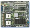
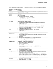
...processors, memory, and power (not on product codes SE7520BD2V and SE7520BD2VD2) ƒ Custom front panel LCD connectors for additional information. Server Board Features Feature Processors Description Up to two Intel® Xeon™ processors with an FC-mPGA4 using Socket 604, and an 800-MHz Front... Slot 2: PCI-X* 64-bit/100 MHz ƒ Slot 3: PCI 32-bit/33MHz ƒ Slot 4: PCI Express* x8 with the Intel® Local Control Panel ƒ Intel® Management Module Professional or Advanced ƒ SSI-EEB3.5 compliant form factor ƒ Board size 12 inches by 13 inches 17 See ...
...processors, memory, and power (not on product codes SE7520BD2V and SE7520BD2VD2) ƒ Custom front panel LCD connectors for additional information. Server Board Features Feature Processors Description Up to two Intel® Xeon™ processors with an FC-mPGA4 using Socket 604, and an 800-MHz Front... Slot 2: PCI-X* 64-bit/100 MHz ƒ Slot 3: PCI 32-bit/33MHz ƒ Slot 4: PCI Express* x8 with the Intel® Local Control Panel ƒ Intel® Management Module Professional or Advanced ƒ SSI-EEB3.5 compliant form factor ƒ Board size 12 inches by 13 inches 17 See ...
User Guide
Page 19
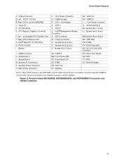
... Graphics Controller F, Left x8 (x4speed) PCI-Express* Slot F, Right x8 PCI-Express Slot G Intel® 82541P1 (10/100/1000) H PCI-X 133 Slot I Battery P CPU Power Connector Q DIMM Sockets R CPU 1 Fan Header S ...N Auxiliary Power Connector O Main Power Connector AA HSBP A BB Front Panel USB CC Front Panel LCP DD IPMB EE SATA A2 FF Speaker GG SATA A1 HH HSBP B II Front Panel Connector JJ SCSI Channel A KK System Fan 1 (3-pin) LL System ...(SCSI Channel B) are not available on product code SE7520BD2. Product Codes SE7520BD2, SE7520BD2SCSI, and SE7520BD2V Connector and Header Locations 19 Figure 2.
... Graphics Controller F, Left x8 (x4speed) PCI-Express* Slot F, Right x8 PCI-Express Slot G Intel® 82541P1 (10/100/1000) H PCI-X 133 Slot I Battery P CPU Power Connector Q DIMM Sockets R CPU 1 Fan Header S ...N Auxiliary Power Connector O Main Power Connector AA HSBP A BB Front Panel USB CC Front Panel LCP DD IPMB EE SATA A2 FF Speaker GG SATA A1 HH HSBP B II Front Panel Connector JJ SCSI Channel A KK System Fan 1 (3-pin) LL System ...(SCSI Channel B) are not available on product code SE7520BD2. Product Codes SE7520BD2, SE7520BD2SCSI, and SE7520BD2V Connector and Header Locations 19 Figure 2.
User Guide
Page 21
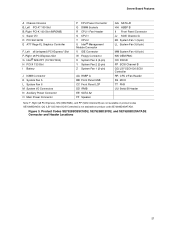
...Slot (MROMB) C Super I/O D PCI Slot 32/33 E ATI* Rage XL Graphics Controller F, Left x8 (x4speed) PCI-Express* Slot F, Right x8 PCI-Express Slot G Intel® 82541P1 (10/100/1000) H PCI-X 133 Slot I Battery J ICMB Connector K System Fan 5 L System Fan 6 M System I/O Connectors N Auxiliary Power Connector O... DIMM Sockets R CPU 1 Fan Header S CPU 1 T CPU 2 U Intel® Management Module Connector V IDE Connector W Floppy Connector X System Fan 2 (3-pin) Y System Fan 2 (2-pin) Z System Fan 1 (2-pin) AA HSBP A BB Front Panel USB CC Front Panel LCP DD IPMB EE SATA A2 FF Speaker GG SATA A1 HH HSBP...
...Slot (MROMB) C Super I/O D PCI Slot 32/33 E ATI* Rage XL Graphics Controller F, Left x8 (x4speed) PCI-Express* Slot F, Right x8 PCI-Express Slot G Intel® 82541P1 (10/100/1000) H PCI-X 133 Slot I Battery J ICMB Connector K System Fan 5 L System Fan 6 M System I/O Connectors N Auxiliary Power Connector O... DIMM Sockets R CPU 1 Fan Header S CPU 1 T CPU 2 U Intel® Management Module Connector V IDE Connector W Floppy Connector X System Fan 2 (3-pin) Y System Fan 2 (2-pin) Z System Fan 1 (2-pin) AA HSBP A BB Front Panel USB CC Front Panel LCP DD IPMB EE SATA A2 FF Speaker GG SATA A1 HH HSBP...
User Guide
Page 23
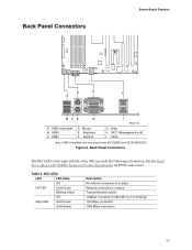
... in place Network connection is available only on or blinking) 100 Mbps connection 1000 Mbps connection 23 See the Intel® Server Board SE7520BD2 Technical Product Specification for POST code errors. Table 4. Back Panel Connectors Server Board Features D F H A B CE G A USB3 (see note)* B USB2 C USB1 D Mouse E Keyboard F Serial A I TP00719 G Video H NIC1 (Management port) I NIC2...
... in place Network connection is available only on or blinking) 100 Mbps connection 1000 Mbps connection 23 See the Intel® Server Board SE7520BD2 Technical Product Specification for POST code errors. Table 4. Back Panel Connectors Server Board Features D F H A B CE G A USB3 (see note)* B USB2 C USB1 D Mouse E Keyboard F Serial A I TP00719 G Video H NIC1 (Management port) I NIC2...
User Guide
Page 47
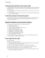
... the system and/or the peripheral devices. 1. See the operating system documentation. ‰ Did you press the system power on/off switch on the front panel to turn off the system and any peripheral cables from the tested components lists? CAUTION Turn off the system and all device drivers properly installed...
... the system and/or the peripheral devices. 1. See the operating system documentation. ‰ Did you press the system power on/off switch on the front panel to turn off the system and any peripheral cables from the tested components lists? CAUTION Turn off the system and all device drivers properly installed...
User Guide
Page 48
... normally? As each mass storage device installed in the order given. If so, the power LED might be defective or the cable from the front panel to the server board might be loose. ‰ Have you securely plugged the server AC power cord into the power supply? ‰ Is the power...
... normally? As each mass storage device installed in the order given. If so, the power LED might be defective or the cable from the front panel to the server board might be loose. ‰ Have you securely plugged the server AC power cord into the power supply? ‰ Is the power...
User Guide
Page 50
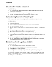
...not operating properly, it is set to a fan that "Onboard Floppy" is an indication of these LEDs lit? ‰ Are any other front panel LEDs lit? ‰ Have any shorted wires caused by pinched-cables or have power connector plugs been forced into a different system? Troubleshooting Characters ...failed? ‰ Are the fan power connectors properly connected to the server board? ‰ Is the cable from the front panel board connected to both the front panel board and the server board? ‰ Are the power supply cables properly connected to "Enabled." Use the server management subsystem ...
...not operating properly, it is set to a fan that "Onboard Floppy" is an indication of these LEDs lit? ‰ Are any other front panel LEDs lit? ‰ Have any shorted wires caused by pinched-cables or have power connector plugs been forced into a different system? Troubleshooting Characters ...failed? ‰ Are the fan power connectors properly connected to the server board? ‰ Is the cable from the front panel board connected to both the front panel board and the server board? ‰ Are the power supply cables properly connected to "Enabled." Use the server management subsystem ...
User Guide
Page 51
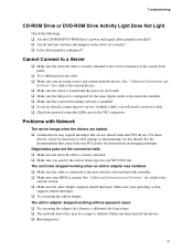
... changing interrupts. Diagnostics pass but the connection fails. ‰ Make sure the network cable is securely attached to the correct connector at the system back panel. ‰ Try a different network cable. ‰ Make sure you will need a crossover cable. ‰ Check the network controller LEDs next to the current version. ‰...
... changing interrupts. Diagnostics pass but the connection fails. ‰ Make sure the network cable is securely attached to the correct connector at the system back panel. ‰ Try a different network cable. ‰ Make sure you will need a crossover cable. ‰ Check the network controller LEDs next to the current version. ‰...
User Guide
Page 52
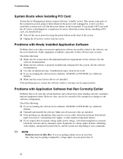
... running it again. If 52 Problems with the power button on your data files, they can also be caused by voltage spikes on the front panel.
... running it again. If 52 Problems with the power button on your data files, they can also be caused by voltage spikes on the front panel.


