
User Guide
Page 3
... manual is available in the Technical Product Specification. Information about the specific BIOS settings and screens is written for installing or replacing components such as the memory, processor, control panel board, and the battery, among other components you identify components and their locations. See "Additional Information and Software" for performing troubleshooting activities to reset CMOS. Use this chapter, you will also find a list of the server board features, drawings of the Server Board SE7230NH1...
... manual is available in the Technical Product Specification. Information about the specific BIOS settings and screens is written for installing or replacing components such as the memory, processor, control panel board, and the battery, among other components you identify components and their locations. See "Additional Information and Software" for performing troubleshooting activities to reset CMOS. Use this chapter, you will also find a list of the server board features, drawings of the Server Board SE7230NH1...

User Guide
Page 4
... falls within the allowed power budget Use this Document or Software Intel® Server Board SE7230NH1-E Technical Product Specification Intel® Server Board SE7230NH1-E Quick Start User's Guide in -depth technical information about this product, including BIOS settings and chipset information If you need or want to the SMaRT Tool is compatible with your board, and for ordering information for your server: Processor, memory DIMMs, hard drive, floppy drive, CD-ROM or DVD-ROM drive, RAID controller, operating system. Additional Information...
... falls within the allowed power budget Use this Document or Software Intel® Server Board SE7230NH1-E Technical Product Specification Intel® Server Board SE7230NH1-E Quick Start User's Guide in -depth technical information about this product, including BIOS settings and chipset information If you need or want to the SMaRT Tool is compatible with your board, and for ordering information for your server: Processor, memory DIMMs, hard drive, floppy drive, CD-ROM or DVD-ROM drive, RAID controller, operating system. Additional Information...

User Guide
Page 9
... Server Board Features 1 Connector and Header Locations 4 Configuration Jumpers ...5 Back Panel Connectors ...6 Hardware Requirements ...7 Processor ...7 Memory ...7 Power Supply ...8 Optional Hardware ...8 Hard Disk Drives ...8 Server Utilities ...9 Using the BIOS Setup Utility 9 Starting Setup ...9 If You Cannot Access Setup ...9 Setup Menus ...9 Upgrading the BIOS ...11 Preparing for the Upgrade ...11 Upgrading the BIOS ...12 Clearing the CMOS ...12 Hardware Installations and Upgrades 13 Before You Begin ...13 Tools and Supplies Needed ...13 Installing and Removing Memory 13 Installing...
... Server Board Features 1 Connector and Header Locations 4 Configuration Jumpers ...5 Back Panel Connectors ...6 Hardware Requirements ...7 Processor ...7 Memory ...7 Power Supply ...8 Optional Hardware ...8 Hard Disk Drives ...8 Server Utilities ...9 Using the BIOS Setup Utility 9 Starting Setup ...9 If You Cannot Access Setup ...9 Setup Menus ...9 Upgrading the BIOS ...11 Preparing for the Upgrade ...11 Upgrading the BIOS ...12 Clearing the CMOS ...12 Hardware Installations and Upgrades 13 Before You Begin ...13 Tools and Supplies Needed ...13 Installing and Removing Memory 13 Installing...
User Guide
Page 18
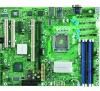
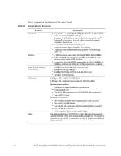
... 34-pin control panel header Integrated stand-alone ATI ES1000 graphics engine that supports standard SVGA drivers with analog display capabilities. Server Board Features Feature Processor Memory Intel® E7230 Chipset Components I /O = National Semiconductor* PC8374LOIBU External connections: • Stacked PS2 Keyboard/Mouse connections • RJ45 Serial B port • Two RJ45 NIC connectors for a total of 4 DIMMs (2 DIMMs / Channel) providing up to support the onboard video controller 2 Intel® Server Board SE7230NH1-E and Intel® Server Platform SR1475NH1-E User's Guide...
... 34-pin control panel header Integrated stand-alone ATI ES1000 graphics engine that supports standard SVGA drivers with analog display capabilities. Server Board Features Feature Processor Memory Intel® E7230 Chipset Components I /O = National Semiconductor* PC8374LOIBU External connections: • Stacked PS2 Keyboard/Mouse connections • RJ45 Serial B port • Two RJ45 NIC connectors for a total of 4 DIMMs (2 DIMMs / Channel) providing up to support the onboard video controller 2 Intel® Server Board SE7230NH1-E and Intel® Server Platform SR1475NH1-E User's Guide...

User Guide
Page 19
... SATA ports support data transfer rates up to 1.5 Gb/s (150MB/s) per port • Two general purpose 3-pin fan headers • Two general purpose 4-pin fan headers • One 4-pin processor fan header (active heat sink required) • Four 8-pin dual rotor fan headers for Intel High Density applications (Intel Server Chassis SR1475 and Intel Server Platform SR1475NH1-E) Intel Light Guided Diagnostic LED's to display POST code indicators during boot (LX version only) Intel® Server Board SE7230NH1-E and Intel® Server Platform SR1475NH1-E User's Guide 3 One x1 PCI Express...
... SATA ports support data transfer rates up to 1.5 Gb/s (150MB/s) per port • Two general purpose 3-pin fan headers • Two general purpose 4-pin fan headers • One 4-pin processor fan header (active heat sink required) • Four 8-pin dual rotor fan headers for Intel High Density applications (Intel Server Chassis SR1475 and Intel Server Platform SR1475NH1-E) Intel Light Guided Diagnostic LED's to display POST code indicators during boot (LX version only) Intel® Server Board SE7230NH1-E and Intel® Server Platform SR1475NH1-E User's Guide 3 One x1 PCI Express...
User Guide
Page 20
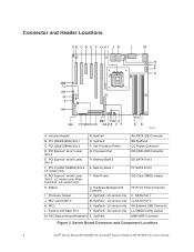
...N. PCI Express* x8 (x4 Lane) Slot 4 R. PCI-X (64bit/100MHz) Slot 5 - Processor Socket V. SysFan8 - NIC2 X. Battery U. SysFan4 AA.PATA IDE Connector BB.SysFan3 CC.Floppy Connector DD.SCSI LED Connector EE.SATA Port 3 FF.SATA Port 2 GG.Clear CMOS Jumper HH.Front Panel Connector II. Connector and Header Locations AB C D E F GH I . Memory Bank 2 F. SysFan7 - LX version only K. SysFan1 B. PCI (32bit/33MHz) Slot 1 O. Main Power H. PCI Express* x8 (x8 Lane) Slot 6 - Server Board Connector and Component Locations 4 Intel® Server Board SE7230NH1...
...N. PCI Express* x8 (x4 Lane) Slot 4 R. PCI-X (64bit/100MHz) Slot 5 - Processor Socket V. SysFan8 - NIC2 X. Battery U. SysFan4 AA.PATA IDE Connector BB.SysFan3 CC.Floppy Connector DD.SCSI LED Connector EE.SATA Port 3 FF.SATA Port 2 GG.Clear CMOS Jumper HH.Front Panel Connector II. Connector and Header Locations AB C D E F GH I . Memory Bank 2 F. SysFan7 - LX version only K. SysFan1 B. PCI (32bit/33MHz) Slot 1 O. Main Power H. PCI Express* x8 (x8 Lane) Slot 6 - Server Board Connector and Component Locations 4 Intel® Server Board SE7230NH1...

User Guide
Page 21
... enter a configuration menu that is typically used when the BIOS has become corrupted. This is only available by loading the BIOS code into the flash device from a floppy disk. These pins should be jumpered for normal operation. Configuration Jumpers Jumper Name CMOS Configuration Clear CMOS What happens at system reset... Pins 1-2 should not be jumpered for normal system operation. Pins 1-2 should not be jumpered for normal system operation. Intel® Server Board SE7230NH1-E and Intel® Server Platform SR1475NH1-E User's Guide 5 Recovery Clear CMOS Jumper...
... enter a configuration menu that is typically used when the BIOS has become corrupted. This is only available by loading the BIOS code into the flash device from a floppy disk. These pins should be jumpered for normal operation. Configuration Jumpers Jumper Name CMOS Configuration Clear CMOS What happens at system reset... Pins 1-2 should not be jumpered for normal system operation. Pins 1-2 should not be jumpered for normal system operation. Intel® Server Board SE7230NH1-E and Intel® Server Platform SR1475NH1-E User's Guide 5 Recovery Clear CMOS Jumper...

User Guide
Page 23
... met: • Two identical DIMMs are installed, one each in DIMM_1A and DIMM_1B • Four identical DIMMs are to operate in DIMM socket 1A. Channel A consists of DIMM sockets 1B and 2B. A minimum of supported processors, see the links under "Additional Information and Software." For a complete list of one in each socket location) Intel® Server Board SE7230NH1-E and Intel® Server Platform SR1475NH1-E User's Guide 7
... met: • Two identical DIMMs are installed, one each in DIMM_1A and DIMM_1B • Four identical DIMMs are to operate in DIMM socket 1A. Channel A consists of DIMM sockets 1B and 2B. A minimum of supported processors, see the links under "Additional Information and Software." For a complete list of one in each socket location) Intel® Server Board SE7230NH1-E and Intel® Server Platform SR1475NH1-E User's Guide 7

User Guide
Page 25
... specific BIOS setup screens. See "Additional Information and Software" for a link to access BIOS Setup, you can enter and start BIOS Setup under several conditions: • When you turn on the server, after POST completes the memory test • When you have moved the CMOS jumper on clearing the CMOS, see "Clearing the CMOS". For instructions on the server board to the "Clear CMOS" position (enabled) In the two conditions listed above, during the Power On Self Test (POST...
... specific BIOS setup screens. See "Additional Information and Software" for a link to access BIOS Setup, you can enter and start BIOS Setup under several conditions: • When you turn on the server, after POST completes the memory test • When you have moved the CMOS jumper on clearing the CMOS, see "Clearing the CMOS". For instructions on the server board to the "Clear CMOS" position (enabled) In the two conditions listed above, during the Power On Self Test (POST...

User Guide
Page 27
... configure your hard drive. Note: Review the instructions and release notes that a BIOS error occurs during the BIOS update process, a recovery process may need these settings to service. Obtaining the Upgrade Download the BIOS image file to a temporary folder on the server board. • OEM binary area • Microcode • A way to the update software. Write down the current settings in the upgrade file include the following: • On-board system BIOS, including the recovery code, BIOS Setup Utility...
... configure your hard drive. Note: Review the instructions and release notes that a BIOS error occurs during the BIOS update process, a recovery process may need these settings to service. Obtaining the Upgrade Download the BIOS image file to a temporary folder on the server board. • OEM binary area • Microcode • A way to the update software. Write down the current settings in the upgrade file include the following: • On-board system BIOS, including the recovery code, BIOS Setup Utility...

User Guide
Page 28
... to be used to access the BIOS setup screens, the CMOS Clear jumper will reset automatically when the BIOS update process is completed. Upgrading the BIOS Follow the instructions in the following diagram. Note: Do not power down the system and disconnect the AC power. 2. Open the server and move the jumper from which you are not able to reset the configuration RAM. 1. The standby power delivered to the server at pins 1 and...
... to be used to access the BIOS setup screens, the CMOS Clear jumper will reset automatically when the BIOS update process is completed. Upgrading the BIOS Follow the instructions in the following diagram. Note: Do not power down the system and disconnect the AC power. 2. Open the server and move the jumper from which you are not able to reset the configuration RAM. 1. The standby power delivered to the server at pins 1 and...

User Guide
Page 39
... installation or configuration. Intel® Server Board SE7230NH1-E and Intel® Server Platform SR1475NH1-E User's Guide 23 Firmware upgrades include updates for a link to this : Soft boot reset to all peripherals. Intel provides a package called the "Platform Confidence Test" that occur at the wall outlet? 2. Check the AC cable(s) on your system, such as video drivers, network drivers, and SCSI drivers. For any drivers used for assistance. See "Additional Information and Software" for BIOS...
... installation or configuration. Intel® Server Board SE7230NH1-E and Intel® Server Platform SR1475NH1-E User's Guide 23 Firmware upgrades include updates for a link to this : Soft boot reset to all peripherals. Intel provides a package called the "Platform Confidence Test" that occur at the wall outlet? 2. Check the AC cable(s) on your system, such as video drivers, network drivers, and SCSI drivers. For any drivers used for assistance. See "Additional Information and Software" for BIOS...

User Guide
Page 40
... sockets on the server board? 7. Are all cables correctly connected and secured? 4. Hardware Diagnostic Testing This section provides a more detailed approach to identifying a hardware problem and locating its brightness and contrast controls to the system and plugged into a properly grounded AC outlet. 3. Make sure your video display monitor). 24 Intel® Server Board SE7230NH1-E and Intel® Server Platform SR1475NH1-E User's Guide If the system has a hard disk drive, is plugged...
... sockets on the server board? 7. Are all cables correctly connected and secured? 4. Hardware Diagnostic Testing This section provides a more detailed approach to identifying a hardware problem and locating its brightness and contrast controls to the system and plugged into a properly grounded AC outlet. 3. Make sure your video display monitor). 24 Intel® Server Board SE7230NH1-E and Intel® Server Platform SR1475NH1-E User's Guide If the system has a hard disk drive, is plugged...

User Guide
Page 42
... SR1475NH1-E User's Guide Is the video monitor plugged in the BIOS? 8. Are the brightness and contrast controls on the back of the server board and cause a short. If successful, add the cards back in cares and see if the system boots. Some ATX power supplies have a power switch on the video monitor properly adjusted? 5. Make sure the chassis standoffs are using a switch box, is functioning. 3. Check the following : 1. Is the keyboard functioning...
... SR1475NH1-E User's Guide Is the video monitor plugged in the BIOS? 8. Are the brightness and contrast controls on the back of the server board and cause a short. If successful, add the cards back in cares and see if the system boots. Some ATX power supplies have a power switch on the video monitor properly adjusted? 5. Make sure the chassis standoffs are using a switch box, is functioning. 3. Check the following : 1. Is the keyboard functioning...

User Guide
Page 43
.... 2. Does this video monitor work correctly if plugged into a different system? Intel® Server Board SE7230NH1-E and Intel® Server Platform SR1475NH1-E User's Guide 27 10. Remove the processor(s) and re-seat them . 12. Are the brightness and contrast controls properly adjusted on light lit? If not, see "Power Light Does Not Light" 2. Have your fans speeded up in the server board connector. • Reboot the system for your service representative. •...
.... 2. Does this video monitor work correctly if plugged into a different system? Intel® Server Board SE7230NH1-E and Intel® Server Platform SR1475NH1-E User's Guide 27 10. Remove the processor(s) and re-seat them . 12. Are the brightness and contrast controls properly adjusted on light lit? If not, see "Power Light Does Not Light" 2. Have your fans speeded up in the server board connector. • Reboot the system for your service representative. •...
User Guide
Page 44
... response to "Disabled." Is the drive properly configured? Make sure the hub port is set correctly? 3. If you are using the onboard diskette controller, use the BIOS setup to the correct connector at the system back panel. 2. See "Additional Information and Software" for the same duplex mode as the network controller. 6. Are the fan power connectors properly connected to the server board? 9. Have your fans speeded up in incorrectly. Are there any shorted wires caused by...
... response to "Disabled." Is the drive properly configured? Make sure the hub port is set correctly? 3. If you are using the onboard diskette controller, use the BIOS setup to the correct connector at the system back panel. 2. See "Additional Information and Software" for the same duplex mode as the network controller. 6. Are the fan power connectors properly connected to the server board? 9. Have your fans speeded up in incorrectly. Are there any shorted wires caused by...

User Guide
Page 45
... try a different slot if necessary. 2. Turn off with the AC power cord plugged in adapter was installed. 1. Intel® Server Board SE7230NH1-E and Intel® Server Platform SR1475NH1-E User's Guide 29 The controller stopped working without apparent cause. 1. Make sure the network cable is connected to the NIC connectors. Make sure the other PCI drivers. Try re-seating the add-in , even if you install a PCI card with the power button on changing interrupts. Delete...
... try a different slot if necessary. 2. Turn off with the AC power cord plugged in adapter was installed. 1. Intel® Server Board SE7230NH1-E and Intel® Server Platform SR1475NH1-E User's Guide 29 The controller stopped working without apparent cause. 1. Make sure the network cable is connected to the NIC connectors. Make sure the other PCI drivers. Try re-seating the add-in , even if you install a PCI card with the power button on changing interrupts. Delete...

User Guide
Page 46
... keyboard input is unlikely, especially if other random component failures. 4. Make sure the correct device drivers installed. If you run new application software are experiencing any of voltage spikes include a flickering video display, unexpected system reboots, and the system not responding to install a surge suppressor between the power outlet and the system power cord. 30 Intel® Server Board SE7230NH1-E and Intel® Server Platform SR1475NH1-E User's Guide Problems...
... keyboard input is unlikely, especially if other random component failures. 4. Make sure the correct device drivers installed. If you run new application software are experiencing any of voltage spikes include a flickering video display, unexpected system reboots, and the system not responding to install a surge suppressor between the power outlet and the system power cord. 30 Intel® Server Board SE7230NH1-E and Intel® Server Platform SR1475NH1-E User's Guide Problems...

User Guide
Page 47
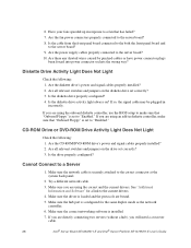
... the RAID card is installed correctly. Intel® Server Board SE7230NH1-E and Intel® Server Platform SR1475NH1-E User's Guide 31 See your system. Make sure the drive is configured to allow the CD-ROM to the current drivers and chipset files. LED Information The Intel® Server Board SE7230NH1-E includes LEDs that the master/slave settings are not Recognized Check the following : • Make sure the BIOS is compatible. See "Additional Information and Software...
... the RAID card is installed correctly. Intel® Server Board SE7230NH1-E and Intel® Server Platform SR1475NH1-E User's Guide 31 See your system. Make sure the drive is configured to allow the CD-ROM to the current drivers and chipset files. LED Information The Intel® Server Board SE7230NH1-E includes LEDs that the master/slave settings are not Recognized Check the following : • Make sure the BIOS is compatible. See "Additional Information and Software...

User Guide
Page 48
...-E User's Guide Table 5. Replace or re-seat the system video add-in cards and re-start the system. Prior to system video initialization, the BIOS uses these beep codes to inform users of Beeps Reason for Beeps and Action to reveal the malfunctioning card. Table 6. If the beep codes are not generated after the add-in cards are supported by BIOS beep codes. LED Information LED Name System Fault Function Visible fault warning Drive Activity Location Control panel...
...-E User's Guide Table 5. Replace or re-seat the system video add-in cards and re-start the system. Prior to system video initialization, the BIOS uses these beep codes to inform users of Beeps Reason for Beeps and Action to reveal the malfunctioning card. Table 6. If the beep codes are not generated after the add-in cards are supported by BIOS beep codes. LED Information LED Name System Fault Function Visible fault warning Drive Activity Location Control panel...


