
Product Guide
Page 4
...Menu ...38 Peripheral Configuration Submenu 39 IDE Configuration ...40 IDE Configuration Submenus 41 Diskette Options ...42 DMI Event Logging ...42 Video Configuration Submenu 43 Resource Configuration Submenu 43 Security Menu ...44 Power Menu ...44 Boot Menu...45 Hard Drive Submenu 46 Removable... Diskette 48 Upgrading the BIOS ...49 Recovering the BIOS...49 Changing the BIOS Language 50 5 Technical Reference Motherboard Connectors...51 Front Panel Connectors ...55 Motherboard Resources...56 Memory Map ...56 DMA Channels ...56 I/O Map ...57 PCI Configuration Space Map 58 Interrupts ...59...
...Menu ...38 Peripheral Configuration Submenu 39 IDE Configuration ...40 IDE Configuration Submenus 41 Diskette Options ...42 DMI Event Logging ...42 Video Configuration Submenu 43 Resource Configuration Submenu 43 Security Menu ...44 Power Menu ...44 Boot Menu...45 Hard Drive Submenu 46 Removable... Diskette 48 Upgrading the BIOS ...49 Recovering the BIOS...49 Changing the BIOS Language 50 5 Technical Reference Motherboard Connectors...51 Front Panel Connectors ...55 Motherboard Resources...56 Memory Map ...56 DMA Channels ...56 I/O Map ...57 PCI Configuration Space Map 58 Interrupts ...59...

Product Guide
Page 5
... 13. Maintenance Menu ...37 5. IDE Configuration ...40 9. Installing the Processor 22 6. Front Panel Connectors 55 Tables 1. SE440BX-2 Motherboard Product Guide A Error Messages BIOS Beep Codes ...61 BIOS Error Messages ...62 B Regulatory and Integration Information Regulatory Compliance ...63...Main Menu...37 6. IDE Configuration Submenus 41 10. Mounting Screw Holes 20 4. Installing the Universal Retention Mechanism 21 5. Video Configuration Submenu 43 13. Installing a DIMM...31 14. Jumper Settings for Intended Applications 66 Figures 1. Setup Function Keys...
... 13. Maintenance Menu ...37 5. IDE Configuration ...40 9. Installing the Processor 22 6. Front Panel Connectors 55 Tables 1. SE440BX-2 Motherboard Product Guide A Error Messages BIOS Beep Codes ...61 BIOS Error Messages ...62 B Regulatory and Integration Information Regulatory Compliance ...63...Main Menu...37 6. IDE Configuration Submenus 41 10. Mounting Screw Holes 20 4. Installing the Universal Retention Mechanism 21 5. Video Configuration Submenu 43 13. Installing a DIMM...31 14. Jumper Settings for Intended Applications 66 Figures 1. Setup Function Keys...
Product Guide
Page 6
... (Optional 54 33. PCI Configuration Space Map 58 39. Safety Regulations ...63 43. I /O Connectors 55 35. Optional Auxiliary Line In Connector (white 53 28. Optional Video In Connector (blue 53 29. DMA Channels ...56 37. Beep Codes...61 41. Security Menu ...44 15. Exit Menu ...46 20. Memory Map ...56 36...
... (Optional 54 33. PCI Configuration Space Map 58 39. Safety Regulations ...63 43. I /O Connectors 55 35. Optional Auxiliary Line In Connector (white 53 28. Optional Video In Connector (blue 53 29. DMA Channels ...56 37. Beep Codes...61 41. Security Menu ...44 15. Exit Menu ...46 20. Memory Map ...56 36...
Product Guide
Page 8
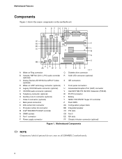
... U Accelerated Graphics Port (AGP) connector V Intel 82371EB PCI ISA IDE Xcelerator (PIIX4E) W PC/PCI connector X Battery Y SMSC FDC37M707 Super I J FF EE K DD CC L M N O BB ZX AA Y W V U A Wake on Ring connector B Yamaha YMF740 (DS1-L) PCI audio controller (optional) C Analog Devices AD1819A SoundPort† Codec (optional) D Wake on all SE440BX-2 motherboards. 8 A B C DE F GH I /O controller Z Flash...
... U Accelerated Graphics Port (AGP) connector V Intel 82371EB PCI ISA IDE Xcelerator (PIIX4E) W PC/PCI connector X Battery Y SMSC FDC37M707 Super I J FF EE K DD CC L M N O BB ZX AA Y W V U A Wake on Ring connector B Yamaha YMF740 (DS1-L) PCI audio controller (optional) C Analog Devices AD1819A SoundPort† Codec (optional) D Wake on all SE440BX-2 motherboards. 8 A B C DE F GH I /O controller Z Flash...
Product Guide
Page 15
... card (NIC) with remote wakeup capabilities. ACPI requires an ACPI-aware operating system. The NIC monitors network traffic at 720 mA. SE440BX-2 Motherboard Product Guide Advanced Configuration and Power Interface (ACPI) ACPI gives the operating system direct control over the power management and Plug and Play... functions of individual devices, add-in boards (some add-in boards may require an ACPI-aware driver), video monitor, and hard disk drives • Methods for achieving less than 30-watt system operation in the ...
... card (NIC) with remote wakeup capabilities. ACPI requires an ACPI-aware operating system. The NIC monitors network traffic at 720 mA. SE440BX-2 Motherboard Product Guide Advanced Configuration and Power Interface (ACPI) ACPI gives the operating system direct control over the power management and Plug and Play... functions of individual devices, add-in boards (some add-in boards may require an ACPI-aware driver), video monitor, and hard disk drives • Methods for achieving less than 30-watt system operation in the ...

Product Guide
Page 17
... has a front panel connector for the location and pinouts of the audio connectors. SE440BX-2 Motherboard Product Guide Audio Connectors The audio connectors include the following: • Stacked backpanel connectors with Line In, Line Out, MIC, ...(black) • Optional telephony connector (green) • Optional auxiliary Line In connector (white) • Optional Video In connector (blue) See Chapter 5 for an offboard speaker. 17 Speaker (Optional) A piezoelectric speaker is mounted on the motherboard. The speaker provides audible error code (beep code) information during the POST.
... has a front panel connector for the location and pinouts of the audio connectors. SE440BX-2 Motherboard Product Guide Audio Connectors The audio connectors include the following: • Stacked backpanel connectors with Line In, Line Out, MIC, ...(black) • Optional telephony connector (green) • Optional auxiliary Line In connector (white) • Optional Video In connector (blue) See Chapter 5 for an offboard speaker. 17 Speaker (Optional) A piezoelectric speaker is mounted on the motherboard. The speaker provides audible error code (beep code) information during the POST.
Product Guide
Page 38
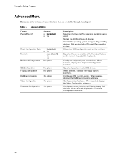
...default) • Yes • Auto (default) • On • Off No options IDE Configuration Floppy Configuration DMI Events Logging Video Configuration Resource Configuration No options No options No options No options No options Description Specifies if a Plug and Play operating system is for ...for setting advanced features that are available through the chipset. No lets the BIOS configure all devices. When selected, displays the Video Configuration submenu. Clears the BIOS configuration data on the numeric keypad of the keyboard. When selected, displays the Floppy Options ...
...default) • Yes • Auto (default) • On • Off No options IDE Configuration Floppy Configuration DMI Events Logging Video Configuration Resource Configuration No options No options No options No options No options Description Specifies if a Plug and Play operating system is for ...for setting advanced features that are available through the chipset. No lets the BIOS configure all devices. When selected, displays the Video Configuration submenu. Clears the BIOS configuration data on the numeric keypad of the keyboard. When selected, displays the Floppy Options ...

Product Guide
Page 39
...will not appear in the list of options for serial port B. Auto assigns LPT1 the address 378h and the interrupt IRQ7. Configures serial port B. SE440BX-2 Motherboard Product Guide Peripheral Configuration Submenu This submenu is for serial port B. Specifies the base I/O address for the other serial port. If an ATI ...mach32† or an ATI mach64† video controller is active as an add-in card, the COM4, 2E8h address will not appear in the list of options for serial port A. continued ...
...will not appear in the list of options for serial port B. Auto assigns LPT1 the address 378h and the interrupt IRQ7. Configures serial port B. SE440BX-2 Motherboard Product Guide Peripheral Configuration Submenu This submenu is for serial port B. Specifies the base I/O address for the other serial port. If an ATI ...mach32† or an ATI mach64† video controller is active as an add-in card, the COM4, 2E8h address will not appear in the list of options for serial port A. continued ...

Product Guide
Page 43
... for the boot display device. DBFF • DC00 - An * (asterisk) displayed next to share a common palette with an ISA add-in video card. Resource Configuration Submenu Feature Memory Reservation IRQ Reservation Options • C800 - Reserves specific IRQs for use by legacy ISA devices. Table 12. Selects... | Reserved Available (default) | Reserved Description Reserves specific upper memory blocks for use by legacy ISA devices. CFFF • D000 - D3FF • D400 - SE440BX-2 Motherboard Product Guide Video Configuration Submenu This submenu is for configuring...
... for the boot display device. DBFF • DC00 - An * (asterisk) displayed next to share a common palette with an ISA add-in video card. Resource Configuration Submenu Feature Memory Reservation IRQ Reservation Options • C800 - Reserves specific IRQs for use by legacy ISA devices. Table 12. Selects... | Reserved Available (default) | Reserved Description Reserves specific upper memory blocks for use by legacy ISA devices. CFFF • D000 - D3FF • D400 - SE440BX-2 Motherboard Product Guide Video Configuration Submenu This submenu is for configuring...
Product Guide
Page 44
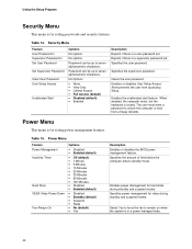
... locked. Select Yes to force the fan to seven alphanumeric characters. Using the Setup Program Security Menu This menu is for video during standby and suspend modes. Reports if there is for hard disks during standby and suspend modes. The user must enter ... standby mode. Specifies power management for setting passwords and security features. Clears the user password. Power Menu Feature Power Management Inactivity Timer Hard Drive VESA Video Power Down Fan Always On Options • Disabled • Enabled (default) • Off (default) • 1 Minute • 5 Minutes &#...
... locked. Select Yes to force the fan to seven alphanumeric characters. Using the Setup Program Security Menu This menu is for video during standby and suspend modes. Reports if there is for hard disks during standby and suspend modes. The user must enter ... standby mode. Specifies power management for setting passwords and security features. Clears the user password. Power Menu Feature Power Management Inactivity Timer Hard Drive VESA Video Power Down Fan Always On Options • Disabled • Enabled (default) • Off (default) • 1 Minute • 5 Minutes &#...
Product Guide
Page 49
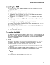
SE440BX-2 Motherboard Product Guide Upgrading the BIOS 1. Select Update System BIOS. Press . 4. Press . 5. When the utility asks for Setup. When the utility displays the message upgrade is .... Insert the bootable BIOS upgrade diskette into memory, select Continue with the BIOS upgrade diskette in the non-erasable boot block area, there is no video support. NOTE Because of the small amount of code available in drive A. Boot the computer with Programming. Select Update Flash Memory From a File. 3. Use the...
SE440BX-2 Motherboard Product Guide Upgrading the BIOS 1. Select Update System BIOS. Press . 4. Press . 5. When the utility asks for Setup. When the utility displays the message upgrade is .... Insert the bootable BIOS upgrade diskette into memory, select Continue with the BIOS upgrade diskette in the non-erasable boot block area, there is no video support. NOTE Because of the small amount of code available in drive A. Boot the computer with Programming. Select Update Flash Memory From a File. 3. Use the...

Product Guide
Page 51
... CD-ROM audio F CD-ROM audio (optional) G Telephony (optional) H Auxiliary Line In (optional) I Video In (optional) J Processor active fan K Fan 1 L Diskette drive M Power supply N SCSI LED (optional) O IDE connectors P PC/PCI Q Configuration jumper block Figure 15. Motherboard Connectors K OM07175 51 5 Technical Reference Motherboard Connectors Figure 15 shows the location of some of the...
... CD-ROM audio F CD-ROM audio (optional) G Telephony (optional) H Auxiliary Line In (optional) I Video In (optional) J Processor active fan K Fan 1 L Diskette drive M Power supply N SCSI LED (optional) O IDE connectors P PC/PCI Q Configuration jumper block Figure 15. Motherboard Connectors K OM07175 51 5 Technical Reference Motherboard Connectors Figure 15 shows the location of some of the...

Product Guide
Page 53
Optional Video In Connector (blue) Pin Signal Name 1 Video_IN-Left 2 Ground 3 Ground 4 Video_IN-Right Table 29. Optional Auxiliary Line In Connector (white) Pin Signal Name 1 Left Line ...) Table 27. Processor Active Fan Connector Pin Signal Name 1 Ground 2 FAN_CTRL (+12 V) 3 FAN_SEN* * If the optional hardware monitor is not available, pin 3 is ground. 53 SE440BX-2 Motherboard Product Guide Table 26. Table 30.
Optional Video In Connector (blue) Pin Signal Name 1 Video_IN-Left 2 Ground 3 Ground 4 Video_IN-Right Table 29. Optional Auxiliary Line In Connector (white) Pin Signal Name 1 Left Line ...) Table 27. Processor Active Fan Connector Pin Signal Name 1 Ground 2 FAN_CTRL (+12 V) 3 FAN_SEN* * If the optional hardware monitor is not available, pin 3 is ground. 53 SE440BX-2 Motherboard Product Guide Table 26. Table 30.
Product Guide
Page 61
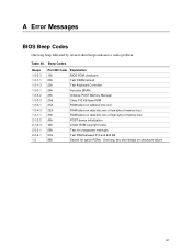
... option ROMs. One long, two short beeps on checksum failure 61 A Error Messages BIOS Beep Codes One long beep followed by several short beeps indicates a video problem.
... option ROMs. One long, two short beeps on checksum failure 61 A Error Messages BIOS Beep Codes One long beep followed by several short beeps indicates a video problem.


