User Guide
Page 7
...://support.intel.com/support/motherboards/server/S5000XVN/. Information about the specific BIOS settings and screens is written for system technicians who are responsible for installing or replacing components such as the memory, processor, and the CMOS battery. Use this chapter for step-by-step instructions and diagrams for troubleshooting, upgrading, and repairing this workstation board. Unless...
...://support.intel.com/support/motherboards/server/S5000XVN/. Information about the specific BIOS settings and screens is written for system technicians who are responsible for installing or replacing components such as the memory, processor, and the CMOS battery. Use this chapter for step-by-step instructions and diagrams for troubleshooting, upgrading, and repairing this workstation board. Unless...
User Guide
Page 8
...-party hardware have been tested and can be used with your workstation: Processor, memory FBDIMMs, hard drive, USB floppy drive, CD-ROM or DVD-ROM drive, RAID controller, operating system. These files are available at http://support.intel.com/support/motherboards/server/S5000XVN viii Intel® Workstation Board S5000XVN See the section on the web page titled Installation and...
...-party hardware have been tested and can be used with your workstation: Processor, memory FBDIMMs, hard drive, USB floppy drive, CD-ROM or DVD-ROM drive, RAID controller, operating system. These files are available at http://support.intel.com/support/motherboards/server/S5000XVN viii Intel® Workstation Board S5000XVN See the section on the web page titled Installation and...

User Guide
Page 9
...Tested Hardware Operating Systems List. Supported Processors. See the section on the web page titled Software & Drivers. Reference Chassis List. Tested Memory List. See the section on the web page titled Compatibility. Intel® Workstation Board S5000XVN ix Firmware Updates. See the section... on the web page titled Installation & Use Intel System Management Software. See the section on the web page titled Installation and...
...Tested Hardware Operating Systems List. Supported Processors. See the section on the web page titled Software & Drivers. Reference Chassis List. Tested Memory List. See the section on the web page titled Compatibility. Intel® Workstation Board S5000XVN ix Firmware Updates. See the section... on the web page titled Installation & Use Intel System Management Software. See the section on the web page titled Installation and...
User Guide
Page 11
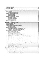
... ...vii Manual Organization ...vii Product Accessories ...viii Additional Information and Software viii Chapter 1: Workstation Board Features 1 Connector and Header Locations 4 Configuration Jumpers ...6 Intel® Light-Guided Diagnostics 8 Back Panel Features ...11 RAID Support ...12 SATA Workstation Board 12 SAS Workstation Board 13 Audio Support ...14 Hardware Requirements ...15 Processor ...15 Memory ...15 Power Supply ...17 Optional Hardware ...18...
... ...vii Manual Organization ...vii Product Accessories ...viii Additional Information and Software viii Chapter 1: Workstation Board Features 1 Connector and Header Locations 4 Configuration Jumpers ...6 Intel® Light-Guided Diagnostics 8 Back Panel Features ...11 RAID Support ...12 SATA Workstation Board 12 SAS Workstation Board 13 Audio Support ...14 Hardware Requirements ...15 Processor ...15 Memory ...15 Power Supply ...17 Optional Hardware ...18...
User Guide
Page 12
... ...27 Tools and Supplies Needed 27 Installing and Removing Memory 27 Installing FBDIMMs ...27 Removing FBDIMMs 30 Installing or Replacing the Processor 30 Installing the Processor 31 Installing the Heatsink(s 34 Removing a Processor 37 Replacing the CMOS Battery 40 Appendix A: Troubleshooting 43 System Boot Quiet Time ...43 Resetting the System ...43 Problems following...
... ...27 Tools and Supplies Needed 27 Installing and Removing Memory 27 Installing FBDIMMs ...27 Removing FBDIMMs 30 Installing or Replacing the Processor 30 Installing the Processor 31 Installing the Heatsink(s 34 Removing a Processor 37 Replacing the CMOS Battery 40 Appendix A: Troubleshooting 43 System Boot Quiet Time ...43 Resetting the System ...43 Problems following...

User Guide
Page 15
...Bank Position 23 Figure 7. Locating and Removing the CMOS Battery 41 xv Connector and Component Locations 4 Figure 3. Opening Processor Socket Lever 32 Figure 13. Opening Load Plate 32 Figure 14. Installing Heatsink (passive heatsink shown 35 Figure 17....7 Figure 4. Password Clear Jumper in the Clear CMOS Position 25 Figure 9. Locating DIMM Sockets 28 Figure 10. Opening Processor Socket Lever 38 Figure 19. Intel® Workstation Board S5000XVN 1 Figure 2. DIMM Sockets...16 Figure 6. List of Figures Figure 1. Removing Protective Cover from Socket 39 Figure 21. Locating...
...Bank Position 23 Figure 7. Locating and Removing the CMOS Battery 41 xv Connector and Component Locations 4 Figure 3. Opening Processor Socket Lever 32 Figure 13. Opening Load Plate 32 Figure 14. Installing Heatsink (passive heatsink shown 35 Figure 17....7 Figure 4. Password Clear Jumper in the Clear CMOS Position 25 Figure 9. Locating DIMM Sockets 28 Figure 10. Opening Processor Socket Lever 38 Figure 19. Intel® Workstation Board S5000XVN 1 Figure 2. DIMM Sockets...16 Figure 6. List of Figures Figure 1. Removing Protective Cover from Socket 39 Figure 21. Locating...
User Guide
Page 20
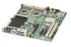
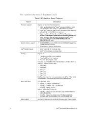
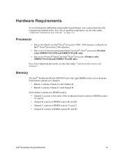
Table 2 summarizes the features of your choice 2 Intel® Workstation Board S5000XVN Product code S5000XVNSATAR and S5000XVNSASR only • Up to two 45nm 2P Dual-Core Intel® Xeon® processors. Product code S5000XVNSATAR and S5000XVNSASR only • Eight FBDIMM sockets (DDR2-533 and DDR2-667) supporting 32 GB maximum memory • Quad-channel memory architecture &#...
Table 2 summarizes the features of your choice 2 Intel® Workstation Board S5000XVN Product code S5000XVNSATAR and S5000XVNSASR only • Up to two 45nm 2P Dual-Core Intel® Xeon® processors. Product code S5000XVNSATAR and S5000XVNSASR only • Eight FBDIMM sockets (DDR2-533 and DDR2-667) supporting 32 GB maximum memory • Quad-channel memory architecture &#...
User Guide
Page 21
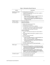
... Gbps or 3 Gbps - Product code S5000XVNSATA or S5000XVNSATAR: Six SATA connectors at 1.5 Gbps or 3 Gbps - Workstation Board Features Feature Hard drive and optical drive support USB drive support I/O control support RAID support Cooling fan support Description &#...Intel® Embedded Server RAID Technology II provides SAS/SATA RAID 0, 1, and 10 with optional RAID 5 support provided by the Intel® RAID Activation Key AXXRAKSW5 • Two 4-pin processor fan connectors • Four 6-pin front fan connectors • Two 4-pin rear fan connectors Intel® Workstation Board S5000XVN...
... Gbps or 3 Gbps - Product code S5000XVNSATA or S5000XVNSATAR: Six SATA connectors at 1.5 Gbps or 3 Gbps - Workstation Board Features Feature Hard drive and optical drive support USB drive support I/O control support RAID support Cooling fan support Description &#...Intel® Embedded Server RAID Technology II provides SAS/SATA RAID 0, 1, and 10 with optional RAID 5 support provided by the Intel® RAID Activation Key AXXRAKSW5 • Two 4-pin processor fan connectors • Four 6-pin front fan connectors • Two 4-pin rear fan connectors Intel® Workstation Board S5000XVN...
User Guide
Page 23
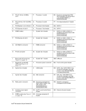
... 1 (SAS 1 is available only with product code S5000XVNSAS or S5000XVNSASR) KK. Chassis intrusion header Intel® Workstation Board S5000XVN 5 PCI-X 64-bit, 100-/133-MHz Q. SATA 1 II. SATA 5 or SAS 3 (SAS 3 is available only with product code S5000XVNSAS or S5000XVNSASR) MM. Processor 2 socket slot 2 C. PCI Express x4 slot 4 S. Front control panel header OO. Serial B / emergency...
... 1 (SAS 1 is available only with product code S5000XVNSAS or S5000XVNSASR) KK. Chassis intrusion header Intel® Workstation Board S5000XVN 5 PCI-X 64-bit, 100-/133-MHz Q. SATA 1 II. SATA 5 or SAS 3 (SAS 3 is available only with product code S5000XVNSAS or S5000XVNSASR) MM. Processor 2 socket slot 2 C. PCI Express x4 slot 4 S. Front control panel header OO. Serial B / emergency...
User Guide
Page 28
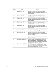
... faulty FBDIMM. This LED indicates a fault has occurred with the processor installed in socket DIMM_C2. This LED indicates a fault has occurred with the FBDIMM installed in socket CPU_2 socket. Replace the faulty unit. 10 Intel® Workstation Board S5000XVN This LED applies only to workstation systems that use an active heatsink. DIMM C2 fault LED O. Replace...
... faulty FBDIMM. This LED indicates a fault has occurred with the processor installed in socket DIMM_C2. This LED indicates a fault has occurred with the FBDIMM installed in socket CPU_2 socket. Replace the faulty unit. 10 Intel® Workstation Board S5000XVN This LED applies only to workstation systems that use an active heatsink. DIMM C2 fault LED O. Replace...
User Guide
Page 33
...® processors 5300 sequence. • One or two 45 nm next generation Quad-Core Intel® Xeon® processors (Product codes S5000XVNSATAR and S5000XVNSASR only) • One or two 45 nm 2P Dual-Core Intel®Xeon® processors (Product codes S5000XVNSATAR and S5000XVNSASR only) For a list of DIMM sockets D1 and D2 Intel® Workstation Board S5000XVN 15
...® processors 5300 sequence. • One or two 45 nm next generation Quad-Core Intel® Xeon® processors (Product codes S5000XVNSATAR and S5000XVNSASR only) • One or two 45 nm 2P Dual-Core Intel®Xeon® processors (Product codes S5000XVNSATAR and S5000XVNSASR only) For a list of DIMM sockets D1 and D2 Intel® Workstation Board S5000XVN 15
User Guide
Page 48
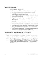
... documentation that came with your chassis for a link to the workstation. Turn off the workstation. 3. Disconnect and remove any parts you install a processor that came with the metal chassis to dissipate the static charge while handling the processor. (2) Avoid moving around unnecessarily. 30 Intel® Workstation Board S5000XVN Removing FBDIMMs To remove a FBDIMM, follow these steps: 1. Observe the...
... documentation that came with your chassis for a link to the workstation. Turn off the workstation. 3. Disconnect and remove any parts you install a processor that came with the metal chassis to dissipate the static charge while handling the processor. (2) Avoid moving around unnecessarily. 30 Intel® Workstation Board S5000XVN Removing FBDIMMs To remove a FBDIMM, follow these steps: 1. Observe the...

User Guide
Page 49
... the safety and ESD precautions in "Safety Information" on removing the cover. 5. A B AF000506 Callout A. Locating Processor Sockets Intel® Workstation Board S5000XVN 31 Turn off all peripheral devices connected to the workstation. Disconnect the AC power cord from the workstation. 4. See the documentation that came with your chassis for instructions on page iii. 2. CPU_1 Figure 11. When...
... the safety and ESD precautions in "Safety Information" on removing the cover. 5. A B AF000506 Callout A. Locating Processor Sockets Intel® Workstation Board S5000XVN 31 Turn off all peripheral devices connected to the workstation. Disconnect the AC power cord from the workstation. 4. See the documentation that came with your chassis for instructions on page iii. 2. CPU_1 Figure 11. When...

User Guide
Page 50
See the documentation that came with your chassis for instructions on the lever attached to the processor socket. Push down on removing chassis components. 7. AF000095 Figure 12. Disconnect and remove any components necessary to disengage the lever from the hook. While ...holding the lever down on the rear tab of the load plate to swing the front of the board to access the processor sockets. Fully open the load plate. Opening Load Plate AF000096 32 Intel® Workstation Board S5000XVN Push down , pull it towards the center of the load plate up slightly. Figure 13. See...
See the documentation that came with your chassis for instructions on the lever attached to the processor socket. Push down on removing chassis components. 7. AF000095 Figure 12. Disconnect and remove any components necessary to disengage the lever from the hook. While ...holding the lever down on the rear tab of the load plate to swing the front of the board to access the processor sockets. Fully open the load plate. Opening Load Plate AF000096 32 Intel® Workstation Board S5000XVN Push down , pull it towards the center of the load plate up slightly. Figure 13. See...

User Guide
Page 51
If the protective cover is attached from Load Plate 10. Close the socket lever. Install the heatsink(s). Set the processor in Place 12. Intel® Workstation Board S5000XVN 33 Setting Processor in the socket with the processor cutouts matching the processor socket notches. Close the load plate. 13. Removing Protective Cover from the load plate, remove it and store...
If the protective cover is attached from Load Plate 10. Close the socket lever. Install the heatsink(s). Set the processor in Place 12. Intel® Workstation Board S5000XVN 33 Setting Processor in the socket with the processor cutouts matching the processor socket notches. Close the load plate. 13. Removing Protective Cover from the load plate, remove it and store...

User Guide
Page 52
...processor requires a heatsink. Depending on the bottom of it . An active heatsink has a fan attached to the top of it and a cable that needs to be connected to use either a passive or an active heatsink. Heatsink Requirements for Compatible Intel® Server Chassis Server Chassis Intel® Entry Server Chassis SC5299-E WS Intel...® Server Chassis SC5400 Base Heatsink Requirement Active heatsink Passive heatsink 34 Intel® Workstation Board S5000XVN Use caution ...
...processor requires a heatsink. Depending on the bottom of it . An active heatsink has a fan attached to the top of it and a cable that needs to be connected to use either a passive or an active heatsink. Heatsink Requirements for Compatible Intel® Server Chassis Server Chassis Intel® Entry Server Chassis SC5299-E WS Intel...® Server Chassis SC5400 Base Heatsink Requirement Active heatsink Passive heatsink 34 Intel® Workstation Board S5000XVN Use caution ...

User Guide
Page 53
... sis AF000098 Figure 16. Use the following steps to install a heatsink. 1. Set the heatsink over the processor, lining up the four captive screws with the four posts surrounding the processor. 3. Installing Heatsink (passive heatsink shown) Intel® Workstation Board S5000XVN 35 In the same order, gradually and equally tighten each captive screw until each is firmly...
... sis AF000098 Figure 16. Use the following steps to install a heatsink. 1. Set the heatsink over the processor, lining up the four captive screws with the four posts surrounding the processor. 3. Installing Heatsink (passive heatsink shown) Intel® Workstation Board S5000XVN 35 In the same order, gradually and equally tighten each captive screw until each is firmly...

User Guide
Page 54
Active heatsink only: Connect the heatsink cable to reach the processor sockets. See the documentation that came with your chassis for instructions on installing the cover. 36 Intel® Workstation Board S5000XVN CPU_2 B. Replace the chassis cover and reconnect the AC power cord. See the documentation that came with your chassis for instructions on installing chassis...
Active heatsink only: Connect the heatsink cable to reach the processor sockets. See the documentation that came with your chassis for instructions on installing the cover. 36 Intel® Workstation Board S5000XVN CPU_2 B. Replace the chassis cover and reconnect the AC power cord. See the documentation that came with your chassis for instructions on installing chassis...

User Guide
Page 55
... seal between the heat sink and the processor. 9. Doing so will cause your workstation to operate your chassis for instructions on removing chassis components. 6. Intel® Workstation Board S5000XVN 37 Remove the chassis cover. Turn off all peripheral devices connected to the workstation. Do not force the heat sink from the workstation board. 7. See the documentation that came with...
... seal between the heat sink and the processor. 9. Doing so will cause your workstation to operate your chassis for instructions on removing chassis components. 6. Intel® Workstation Board S5000XVN 37 Remove the chassis cover. Turn off all peripheral devices connected to the workstation. Do not force the heat sink from the workstation board. 7. See the documentation that came with...

User Guide
Page 56
10. Push down on the lever attached to disengage the lever from the hook. Figure 19. See Figure 18. Fully open the lever. See Figure 19. Opening Load Plate AF000415 38 Intel® Workstation Board S5000XVN AF000095 Figure 18. Fully open the load plate. Opening Processor Socket Lever 11. While holding the lever down on the rear tab of the load plate to swing the front of the board to the processor socket. Push down , pull it towards the center of the load plate up slightly.
10. Push down on the lever attached to disengage the lever from the hook. Figure 19. See Figure 18. Fully open the lever. See Figure 19. Opening Load Plate AF000415 38 Intel® Workstation Board S5000XVN AF000095 Figure 18. Fully open the load plate. Opening Processor Socket Lever 11. While holding the lever down on the rear tab of the load plate to swing the front of the board to the processor socket. Push down , pull it towards the center of the load plate up slightly.


