User Guide
Page 2
Intel's own chassis are designed and tested to meet the intended thermal requirements of these components when the fully integrated system is the responsibility of the system integrator that chooses not to use Intel developed server building blocks ... intellectual property rights is provided in connection with Intel® products. Intel workstation boards contain a number of airflow required for a particular purpose, merchantability, or infringement of others. All Rights Reserved ii Intel® Workstation Board S5000XVN Disclaimer Information in this document. No license, ...
Intel's own chassis are designed and tested to meet the intended thermal requirements of these components when the fully integrated system is the responsibility of the system integrator that chooses not to use Intel developed server building blocks ... intellectual property rights is provided in connection with Intel® products. Intel workstation boards contain a number of airflow required for a particular purpose, merchantability, or infringement of others. All Rights Reserved ii Intel® Workstation Board S5000XVN Disclaimer Information in this document. No license, ...

User Guide
Page 3
... Dokument, bevor Sie eine der Anweisungen ausführen. Vea Intel Server Boards and Server Chassis Safety Information en el Intel® Server Deployment Toolkit 2.0 CD y/o en http:// support.intel.com/support/motherboards/server/sb/cs-010770.htm. Beachten Sie hierzu auch die Sicherheitshinweise...este documento antes de realizar cualquiera de las instrucciones. See also Intel Server Boards and Server Chassis Safety Information on the Intel® Server Deployment Toolkit 2.0 CD and/or at http://support.intel.com/support/ motherboards/server/sb/cs-010770.htm. Consignes de sécurité...
... Dokument, bevor Sie eine der Anweisungen ausführen. Vea Intel Server Boards and Server Chassis Safety Information en el Intel® Server Deployment Toolkit 2.0 CD y/o en http:// support.intel.com/support/motherboards/server/sb/cs-010770.htm. Beachten Sie hierzu auch die Sicherheitshinweise...este documento antes de realizar cualquiera de las instrucciones. See also Intel Server Boards and Server Chassis Safety Information on the Intel® Server Deployment Toolkit 2.0 CD and/or at http://support.intel.com/support/ motherboards/server/sb/cs-010770.htm. Consignes de sécurité...

User Guide
Page 4
http://support.intel.com/support/motherboards/server/sb/CS-010770.htm 上的 Intel Server Boards and Server Chassis Safety Information(《Intel iv Intel® Workstation Board S5000XVN
http://support.intel.com/support/motherboards/server/sb/CS-010770.htm 上的 Intel Server Boards and Server Chassis Safety Information(《Intel iv Intel® Workstation Board S5000XVN
User Guide
Page 5
... board wrapper. Intel® Workstation Board S5000XVN v Turn off the system AC power. ESD and handling boards: Always handle boards carefully. After removing a board from its protective wrapper or from the workstation, place the board component side up on /off: The power button DOES NOT turn off the workstation and disconnect the power cord, telecommunications systems, networks, and modems attached to chassis...
... board wrapper. Intel® Workstation Board S5000XVN v Turn off the system AC power. ESD and handling boards: Always handle boards carefully. After removing a board from its protective wrapper or from the workstation, place the board component side up on /off: The power button DOES NOT turn off the workstation and disconnect the power cord, telecommunications systems, networks, and modems attached to chassis...
User Guide
Page 7
...be noted in the Technical Product Specification. This document provides a brief overview of the features of the board/chassis, a list of the Intel® Workstation Board S5000XVN are available. This includes how to navigate through the BIOS Setup screens, how to perform a BIOS update...memory, processor, and the CMOS battery. In this manual, see http://support.intel.com/support/motherboards/server/S5000XVN/. Chapter 3 provides instructions on how to all versions of the Workstation Board S5000XVN. Preface About this Manual Thank you for purchasing and using the utilities that ...
...be noted in the Technical Product Specification. This document provides a brief overview of the features of the board/chassis, a list of the Intel® Workstation Board S5000XVN are available. This includes how to navigate through the BIOS Setup screens, how to perform a BIOS update...memory, processor, and the CMOS battery. In this manual, see http://support.intel.com/support/motherboards/server/S5000XVN/. Chapter 3 provides instructions on how to all versions of the Workstation Board S5000XVN. Preface About this Manual Thank you for purchasing and using the utilities that ...
User Guide
Page 8
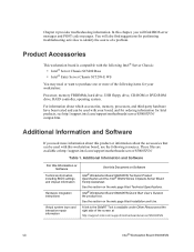
... 1. These files are available at the right side of the following Intel® Server Chassis: • Intel® Server Chassis SC5400 Base • Intel® Entry Server Chassis SC5299-E WS You may need more of the screen at http://support.intel.com/support/motherboards/server/S5000XVN viii Intel® Workstation Board S5000XVN Intel® Workstation Board S5000XVN Quick Start User's Guide in the product box. See the...
... 1. These files are available at the right side of the following Intel® Server Chassis: • Intel® Server Chassis SC5400 Base • Intel® Entry Server Chassis SC5299-E WS You may need more of the screen at http://support.intel.com/support/motherboards/server/S5000XVN viii Intel® Workstation Board S5000XVN Intel® Workstation Board S5000XVN Quick Start User's Guide in the product box. See the...

User Guide
Page 9
.... See the section on the web page titled Compatibility. Table 1. Firmware Updates. Diagnostics. Intel® Workstation Board S5000XVN ix Reference Chassis List. See the section on the web page titled Software & Drivers. See the section on the web page titled Installation & Use Intel System Management Software. See the section on the web page titled Compatibility. See...
.... See the section on the web page titled Compatibility. Table 1. Firmware Updates. Diagnostics. Intel® Workstation Board S5000XVN ix Reference Chassis List. See the section on the web page titled Software & Drivers. See the section on the web page titled Installation & Use Intel System Management Software. See the section on the web page titled Compatibility. See...
User Guide
Page 17
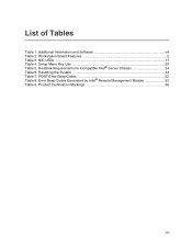
Resetting the System 43 Table 7. Workstation Board Features 2 Table 3. NIC LEDs ...11 Table 4. List of Tables Table 1. Setup Menu Key Use 20 Table 5. POST Error Beep Codes 52 Table 8. Error Beep Codes Generated by Intel® Remote Management Module 53 Table 9. Product Certification Markings 56 xvii Additional Information and Software viii Table 2. Heatsink Requirements for Compatible Intel® Server Chassis 34 Table 6.
Resetting the System 43 Table 7. Workstation Board Features 2 Table 3. NIC LEDs ...11 Table 4. List of Tables Table 1. Setup Menu Key Use 20 Table 5. POST Error Beep Codes 52 Table 8. Error Beep Codes Generated by Intel® Remote Management Module 53 Table 9. Product Certification Markings 56 xvii Additional Information and Software viii Table 2. Heatsink Requirements for Compatible Intel® Server Chassis 34 Table 6.
User Guide
Page 23
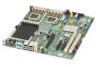
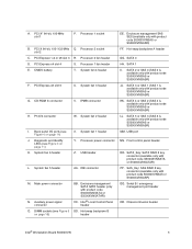
...) MM. Processor 2 fan header D. PCI Express x4 slot 4 S. System fan 3 header G. IPMB connector H. IDE connector M. Intel® Local Control Panel header DD. Hot-swap backplane B header EE. Hot-swap backplane A header GG. SATA 2 or SAS ... S5000XVNSATA or S5000XVNSATAR) PP. SATA 4 or SAS 2 (SAS 2 is available only with product code S5000XVNSAS or S5000XVNSASR) FF. Chassis intrusion header Intel® Workstation Board S5000XVN 5 Processor 1 socket B. Back panel I . Processor power connector Z. USB header L. CMOS battery T. Main power connector N. PCI...
...) MM. Processor 2 fan header D. PCI Express x4 slot 4 S. System fan 3 header G. IPMB connector H. IDE connector M. Intel® Local Control Panel header DD. Hot-swap backplane B header EE. Hot-swap backplane A header GG. SATA 2 or SAS ... S5000XVNSATA or S5000XVNSATAR) PP. SATA 4 or SAS 2 (SAS 2 is available only with product code S5000XVNSAS or S5000XVNSASR) FF. Chassis intrusion header Intel® Workstation Board S5000XVN 5 Processor 1 socket B. Back panel I . Processor power connector Z. USB header L. CMOS battery T. Main power connector N. PCI...
User Guide
Page 27
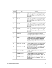
... a description of lit POST LEDs is used to identify specific errors that might occur during the boot process. See your server chassis documentation for instructions to replace the fan. This LED indicates a fault has occurred with system fan 5. Replace the faulty FBDIMM....status LED indicates whether a system is used to identify specific errors that might occur during the boot process. Replace the faulty FBDIMM. Intel® Workstation Board S5000XVN 9 Bit 3 LED B. LSB LED C. DIMM B1 fault LED Function POST LED. This LED indicates a fault has occurred with the...
... a description of lit POST LEDs is used to identify specific errors that might occur during the boot process. See your server chassis documentation for instructions to replace the fan. This LED indicates a fault has occurred with system fan 5. Replace the faulty FBDIMM....status LED indicates whether a system is used to identify specific errors that might occur during the boot process. Replace the faulty FBDIMM. Intel® Workstation Board S5000XVN 9 Bit 3 LED B. LSB LED C. DIMM B1 fault LED Function POST LED. This LED indicates a fault has occurred with the...

User Guide
Page 36
... server chassis for additional drive information and drive installation instructions. See Figure 2 on page 4 to enable RAID 5 support on the workstation board. Intel® Local Control Panel The Intel® Local Control Panel provides enhanced system control by utilizing a LCD display, which provides additional controls and indicators beyond the standard control panel. 18 Intel® Workstation Board S5000XVN Hard...
... server chassis for additional drive information and drive installation instructions. See Figure 2 on page 4 to enable RAID 5 support on the workstation board. Intel® Local Control Panel The Intel® Local Control Panel provides enhanced system control by utilizing a LCD display, which provides additional controls and indicators beyond the standard control panel. 18 Intel® Workstation Board S5000XVN Hard...

User Guide
Page 41
... the jumper from the normal operation position, covering pins 2 and 3, to the previous BIOS: 1. Intel® Workstation Board S5000XVN 23 Power down the workstation and disconnect the AC power. 2. See your workstation will boot to the previously installed BIOS. See Figure 6. 4. Close the chassis. 6. To revert to the Bank_0 position, covering pins 1 and 2, as shown by the...
... the jumper from the normal operation position, covering pins 2 and 3, to the previous BIOS: 1. Intel® Workstation Board S5000XVN 23 Power down the workstation and disconnect the AC power. 2. See your workstation will boot to the previously installed BIOS. See Figure 6. 4. Close the chassis. 6. To revert to the Bank_0 position, covering pins 1 and 2, as shown by the...

User Guide
Page 42
... password clear jumper into the "clear" position clears both passwords. Open the chassis. Locate the Password Clear jumper block at board position J1D2. Power up the workstation. 24 Intel® Workstation Board S5000XVN See your chassis documentation for instructions on removing the chassis cover. 3. Power up the workstation and wait 10 seconds. 6. Password Clear Jumper in Clear Password Position 5. Power...
... password clear jumper into the "clear" position clears both passwords. Open the chassis. Locate the Password Clear jumper block at board position J1D2. Power up the workstation. 24 Intel® Workstation Board S5000XVN See your chassis documentation for instructions on removing the chassis cover. 3. Power up the workstation and wait 10 seconds. 6. Password Clear Jumper in Clear Password Position 5. Power...

User Guide
Page 43
... to the CMOS Clear position, covering pins 2 and 3, as shown by the diagram. Intel® Workstation Board S5000XVN 25 Power down the system. See Figure 8. 4. See your chassis documentation for instructions on removing the chassis cover. 3. Locate the CMOS Clr jumper block at board position J1D1. Move the jumper from the normal operation position, covering pins 1 and... are not able to access the BIOS setup screens, the CMOS Clear jumper will need to be used to reset the configuration RAM. 1. Close the chassis. 8. Power up the workstation.
... to the CMOS Clear position, covering pins 2 and 3, as shown by the diagram. Intel® Workstation Board S5000XVN 25 Power down the system. See Figure 8. 4. See your chassis documentation for instructions on removing the chassis cover. 3. Locate the CMOS Clr jumper block at board position J1D1. Move the jumper from the normal operation position, covering pins 1 and... are not able to access the BIOS setup screens, the CMOS Clear jumper will need to be used to reset the configuration RAM. 1. Close the chassis. 8. Power up the workstation.
User Guide
Page 45
... instructions on page viii for a discussion of the board. DIMM_A1 is the socket closest to the MCH. Turn off the workstation. 3. Disconnect the AC power cord from the inside of the memory requirements and options. Remove the chassis cover. See the documentation that came with your chassis for the FBDIMMs displays DIMM_A1, DIMM_A2, DIMM_B1...
... instructions on page viii for a discussion of the board. DIMM_A1 is the socket closest to the MCH. Turn off the workstation. 3. Disconnect the AC power cord from the inside of the memory requirements and options. Remove the chassis cover. See the documentation that came with your chassis for the FBDIMMs displays DIMM_A1, DIMM_A2, DIMM_B1...
User Guide
Page 46
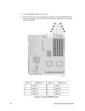
Locate the DIMM sockets (see Figure 9). 6. B. C. DIMM_C2 G. DIMM_D2 Figure 9. Disconnect and remove any components necessary to access the DIMM sockets. DIMM_C1 F. D C B A E F G H AF000503 Callout A. 5. DIMM Socket Callout DIMM Socket DIMM_A1 DIMM_A2 DIMM_B1 DIMM_B2 E. DIMM_D1 H. Locating DIMM Sockets 28 Intel® Workstation Board S5000XVN See the documentation that came with your chassis for instructions on removing chassis components. D.
Locate the DIMM sockets (see Figure 9). 6. B. C. DIMM_C2 G. DIMM_D2 Figure 9. Disconnect and remove any components necessary to access the DIMM sockets. DIMM_C1 F. D C B A E F G H AF000503 Callout A. 5. DIMM Socket Callout DIMM Socket DIMM_A1 DIMM_A2 DIMM_B1 DIMM_B2 E. DIMM_D1 H. Locating DIMM Sockets 28 Intel® Workstation Board S5000XVN See the documentation that came with your chassis for instructions on removing chassis components. D.
User Guide
Page 47
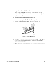
...9. Align the notch on the bottom edge of the FBDIMM with your chassis for instructions on the top edge of the DIMM socket(s) are pushed outward to reach the DIMM sockets. Intel® Workstation Board S5000XVN 29 Make sure the clips latch firmly in Figure 10. 8. Installing ...FBDIMMs 13. 7. See letter "D" in Figure 10. 12. Replace the chassis cover and reconnect the AC power cord. The arrow ...
...9. Align the notch on the bottom edge of the FBDIMM with your chassis for instructions on the top edge of the DIMM socket(s) are pushed outward to reach the DIMM sockets. Intel® Workstation Board S5000XVN 29 Make sure the clips latch firmly in Figure 10. 8. Installing ...FBDIMMs 13. 7. See letter "D" in Figure 10. 12. Replace the chassis cover and reconnect the AC power cord. The arrow ...
User Guide
Page 48
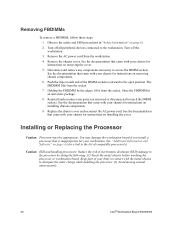
... Caution: Processor must be appropriate: You may damage the workstation board if you removed or disconnected to access the DIMM sockets. Turn off the workstation. 3. See the documentation that came with your chassis for instructions on removing the cover. 5. See the documentation... the DIMM socket(s) outward to dissipate the static charge while handling the processor. (2) Avoid moving around unnecessarily. 30 Intel® Workstation Board S5000XVN Replace the chassis cover and reconnect the AC power cord. Removing FBDIMMs To remove a FBDIMM, follow these steps: 1. See the ...
... Caution: Processor must be appropriate: You may damage the workstation board if you removed or disconnected to access the DIMM sockets. Turn off the workstation. 3. See the documentation that came with your chassis for instructions on removing the cover. 5. See the documentation... the DIMM socket(s) outward to dissipate the static charge while handling the processor. (2) Avoid moving around unnecessarily. 30 Intel® Workstation Board S5000XVN Replace the chassis cover and reconnect the AC power cord. Removing FBDIMMs To remove a FBDIMM, follow these steps: 1. See the ...

User Guide
Page 49
... (see Figure 11). CPU_1 Figure 11. Locating Processor Sockets Intel® Workstation Board S5000XVN 31 Disconnect the AC power cord from the workstation. 4. Processor Socket Callout Processor Socket CPU_2 B. Observe the safety and ESD precautions in "Safety Information" on removing the cover. 5. Turn off the workstation. 3. Remove the chassis cover. See the documentation that came with your...
... (see Figure 11). CPU_1 Figure 11. Locating Processor Sockets Intel® Workstation Board S5000XVN 31 Disconnect the AC power cord from the workstation. 4. Processor Socket Callout Processor Socket CPU_2 B. Observe the safety and ESD precautions in "Safety Information" on removing the cover. 5. Turn off the workstation. 3. Remove the chassis cover. See the documentation that came with your...

User Guide
Page 50
...the load plate to swing the front of the board to disengage the lever from the hook. Push down on removing chassis components. 7. See Figure 12. Fully open the lever. Opening Load Plate AF000096 32 Intel® Workstation Board S5000XVN AF000095 Figure 12. See Figure 13. See ...the documentation that came with your chassis for instructions on the lever attached to access...
...the load plate to swing the front of the board to disengage the lever from the hook. Push down on removing chassis components. 7. See Figure 12. Fully open the lever. Opening Load Plate AF000096 32 Intel® Workstation Board S5000XVN AF000095 Figure 12. See Figure 13. See ...the documentation that came with your chassis for instructions on the lever attached to access...