
User Guide
Page 15
... Plate 38 Figure 20. Password Clear Jumper in Place 33 Figure 16. Removing Protective Cover from Socket 39 Figure 21. Intel® Workstation Board S5000XVN 1 Figure 2. CMOS Clear Jumper in Force Lower Bank Position 23 Figure 7. Opening Load Plate 32 Figure 14. Installing ...Heatsink (passive heatsink shown 35 Figure 17. Back Panel Connectors and LEDs 11 Figure 5. Locating DIMM Sockets 28 Figure 10. Installing ...
... Plate 38 Figure 20. Password Clear Jumper in Place 33 Figure 16. Removing Protective Cover from Socket 39 Figure 21. Intel® Workstation Board S5000XVN 1 Figure 2. CMOS Clear Jumper in Force Lower Bank Position 23 Figure 7. Opening Load Plate 32 Figure 14. Installing ...Heatsink (passive heatsink shown 35 Figure 17. Back Panel Connectors and LEDs 11 Figure 5. Locating DIMM Sockets 28 Figure 10. Installing ...
User Guide
Page 21
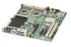
... Server RAID Technology II provides SAS/SATA RAID 0, 1, and 10 with optional RAID 5 support provided by the Intel® RAID Activation Key AXXRAKSW5 • Two 4-pin processor fan connectors • Four 6-pin front fan connectors • Two 4-pin rear fan connectors Intel® Workstation Board S5000XVN 3 Product code S5000XVNSATA or S5000XVNSATAR: Six SATA connectors at 1.5 Gbps...
... Server RAID Technology II provides SAS/SATA RAID 0, 1, and 10 with optional RAID 5 support provided by the Intel® RAID Activation Key AXXRAKSW5 • Two 4-pin processor fan connectors • Four 6-pin front fan connectors • Two 4-pin rear fan connectors Intel® Workstation Board S5000XVN 3 Product code S5000XVNSATA or S5000XVNSATAR: Six SATA connectors at 1.5 Gbps...

User Guide
Page 24
...should not be jumpered for the CMOS to be reset with the jumpers on pins 2 - 3 for normal operation. The workstation does not need to 10 seconds. Power on the next workstation reset. Protect CMOS: these pins should be jumpered for 5 to be cleared. Erase CMOS: If these pins for normal ...Boot from the standard BIOS. Place the jumper on these pins are jumpered for normal operation. These pins should be cleared on the workstation 6 Intel® Workstation Board S5000XVN Move the jumper back to 10 seconds, the CMOS settings will be jumpered for 5 to pins 1 - 2.
...should not be jumpered for the CMOS to be reset with the jumpers on pins 2 - 3 for normal operation. The workstation does not need to 10 seconds. Power on the next workstation reset. Protect CMOS: these pins should be jumpered for 5 to be cleared. Erase CMOS: If these pins for normal ...Boot from the standard BIOS. Place the jumper on these pins are jumpered for normal operation. These pins should be cleared on the workstation 6 Intel® Workstation Board S5000XVN Move the jumper back to 10 seconds, the CMOS settings will be jumpered for 5 to pins 1 - 2.

User Guide
Page 25
Move the jumper back to 10 seconds. To use this jumper to 10 seconds, the password will be jumpered for normal operation. Place the jumper on the workstation. Configuration Jumpers Intel® Workstation Board S5000XVN 7 Erase password: If these pins are jumpered for 5 to reset the password: Power down the workstation. These pins should not be cleared on the...
Move the jumper back to 10 seconds. To use this jumper to 10 seconds, the password will be jumpered for normal operation. Place the jumper on the workstation. Configuration Jumpers Intel® Workstation Board S5000XVN 7 Erase password: If these pins are jumpered for 5 to reset the password: Power down the workstation. These pins should not be cleared on the...
User Guide
Page 28
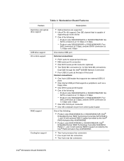
... indicates a fault has occurred with the FBDIMM installed in socket CPU_2 socket. Replace the faulty processor. Replace the faulty unit. 10 Intel® Workstation Board S5000XVN LED DIMM B2 fault LED M. DIMM D2 fault LED Q. +5-volt standby LED R. This LED indicates a fault has occurred with...occurred with fan that is installed on the heatsink for processor 2. This LED indicates a fault has occurred with fan that is applied to workstation systems that use an active heatsink. Callout L. DIMM C1 fault LED N. DIMM C2 fault LED O. DIMM D1 fault LED P. Processor 1...
... indicates a fault has occurred with the FBDIMM installed in socket CPU_2 socket. Replace the faulty processor. Replace the faulty unit. 10 Intel® Workstation Board S5000XVN LED DIMM B2 fault LED M. DIMM D2 fault LED Q. +5-volt standby LED R. This LED indicates a fault has occurred with...occurred with fan that is installed on the heatsink for processor 2. This LED indicates a fault has occurred with fan that is applied to workstation systems that use an active heatsink. Callout L. DIMM C1 fault LED N. DIMM C2 fault LED O. DIMM D1 fault LED P. Processor 1...

User Guide
Page 29
... LJ H A. NIC 1 D. NIC 2 E. Bit 2 LED (POST LED) L. Table 3. Audio in place Transmit / receive activity is occurring 10 Mbps connection (if left of each NIC provide the following information. LSB LED (POST LED) J. Serial A C. NIC LEDs LED Left Right LED ... M. ID LED N. Audio out G. Status LED O. For information about the LEDs, see "Intel® Light-Guided Diagnostics" on or blinking) 100 Mbps connection 1000 Mbps connection Intel® Workstation Board S5000XVN 11 Keyboard Figure 4. USB (four ports) I. Back Panel Features The diagram and table show the...
... LJ H A. NIC 1 D. NIC 2 E. Bit 2 LED (POST LED) L. Table 3. Audio in place Transmit / receive activity is occurring 10 Mbps connection (if left of each NIC provide the following information. LSB LED (POST LED) J. Serial A C. NIC LEDs LED Left Right LED ... M. ID LED N. Audio out G. Status LED O. For information about the LEDs, see "Intel® Light-Guided Diagnostics" on or blinking) 100 Mbps connection 1000 Mbps connection Intel® Workstation Board S5000XVN 11 Keyboard Figure 4. USB (four ports) I. Back Panel Features The diagram and table show the...
User Guide
Page 30
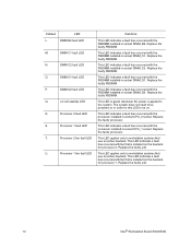
...configurations. The "Onboard SATA Controller" option is enabled by "Configure SATA as RAID". RAID Support The Intel® Workstation Board S5000XVN is desired, the optional Intel® RAID Activation Key AXXRAKSW5 accessory must be set to either Legacy or Enhanced. • Legacy ...Gbps and 3.0 Gbps data transfer rates. The Intel® Embedded Server RAID Technology II feature provides RAID modes 0, 1, and 10. See Figure 2 on the Advanced | ATA Controller setup page, some of the Intel® Workstation Board S5000XVN (product code S5000XVNSATA or S5000XVNSATAR) provide an ...
...configurations. The "Onboard SATA Controller" option is enabled by "Configure SATA as RAID". RAID Support The Intel® Workstation Board S5000XVN is desired, the optional Intel® RAID Activation Key AXXRAKSW5 accessory must be set to either Legacy or Enhanced. • Legacy ...Gbps and 3.0 Gbps data transfer rates. The Intel® Embedded Server RAID Technology II feature provides RAID modes 0, 1, and 10. See Figure 2 on the Advanced | ATA Controller setup page, some of the Intel® Workstation Board S5000XVN (product code S5000XVNSATA or S5000XVNSATAR) provide an ...
User Guide
Page 31
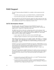
... Guide for Pedestal Systems with the accessory kit. Notes: • For help with navigating the BIOS Setup utility, see the Intel® Workstation Board S5000XVN Technical Product Specification. • For help with enclosure management cabling, see the documentation that is not available. The SAS controller ... logical drives. See Figure 2 on page 4 for the four blue ports on the workstation board continue to function as either SAS or SATA ports. This enables SAS RAID modes 0, 1, or 10 for connection locations. To enable RAID 5, this SAS controller supports up to 3.0 Gbps ...
... Guide for Pedestal Systems with the accessory kit. Notes: • For help with navigating the BIOS Setup utility, see the Intel® Workstation Board S5000XVN Technical Product Specification. • For help with enclosure management cabling, see the documentation that is not available. The SAS controller ... logical drives. See Figure 2 on page 4 for the four blue ports on the workstation board continue to function as either SAS or SATA ports. This enables SAS RAID modes 0, 1, or 10 for connection locations. To enable RAID 5, this SAS controller supports up to 3.0 Gbps ...

User Guide
Page 32
... and mic 2 are both input and output capable. Analog IOs are stereo input and output re- Audio Support The Intel® Workstation Board S5000XVN includes the Realtec* ALC260 2-channel highdefinition audio codec with 1dB mixer gain for fine volume control • Impedance-sensing ... gaming experience • 10-band software equalizer • Enhanced configuration panel and device sensing wizard to improve user experience • Content copy protection for S/PDIF interface • Mono / stereo microphone noise suppression 14 Intel® Workstation Board S5000XVN tasking • Mono ...
... and mic 2 are both input and output capable. Analog IOs are stereo input and output re- Audio Support The Intel® Workstation Board S5000XVN includes the Realtec* ALC260 2-channel highdefinition audio codec with 1dB mixer gain for fine volume control • Impedance-sensing ... gaming experience • 10-band software equalizer • Enhanced configuration panel and device sensing wizard to improve user experience • Content copy protection for S/PDIF interface • Mono / stereo microphone noise suppression 14 Intel® Workstation Board S5000XVN tasking • Mono ...

User Guide
Page 42
...3, as shown by the diagram. See Figure 7. 4. Password Clear Jumper in Clear Password Position 5. Power up the workstation. 24 Intel® Workstation Board S5000XVN See your chassis documentation for instructions on removing the chassis cover. 3. Move the jumper from the normal operation position, ...the Password Clear jumper back to the original position, covering pins 1 and 2. 8. Power up the workstation and wait 10 seconds. 6. Power down the workstation. Clearing the Password If the user or administrator password(s) is lost or forgotten, moving the password clear...
...3, as shown by the diagram. See Figure 7. 4. Password Clear Jumper in Clear Password Position 5. Power up the workstation. 24 Intel® Workstation Board S5000XVN See your chassis documentation for instructions on removing the chassis cover. 3. Move the jumper from the normal operation position, ...the Password Clear jumper back to the original position, covering pins 1 and 2. 8. Power up the workstation and wait 10 seconds. 6. Power down the workstation. Clearing the Password If the user or administrator password(s) is lost or forgotten, moving the password clear...

User Guide
Page 43
...the original position, covering pins 1 and 2. 7. Open the chassis. See Figure 8. 4. Wait 10 seconds. 6. Close the chassis. 8. See your chassis documentation for instructions on removing the chassis cover. 3. Power up the workstation. Leave the AC power cord connected. 2. CMOS CLR Default 2 Clear 3 CMOS J1D1 AF000505 ...to the CMOS Clear position, covering pins 2 and 3, as shown by the diagram. Locate the CMOS Clr jumper block at board position J1D1. CMOS Clear Jumper in the Clear CMOS Position 5. Intel® Workstation Board S5000XVN 25 Power down the system.
...the original position, covering pins 1 and 2. 7. Open the chassis. See Figure 8. 4. Wait 10 seconds. 6. Close the chassis. 8. See your chassis documentation for instructions on removing the chassis cover. 3. Power up the workstation. Leave the AC power cord connected. 2. CMOS CLR Default 2 Clear 3 CMOS J1D1 AF000505 ...to the CMOS Clear position, covering pins 2 and 3, as shown by the diagram. Locate the CMOS Clr jumper block at board position J1D1. CMOS Clear Jumper in the Clear CMOS Position 5. Intel® Workstation Board S5000XVN 25 Power down the system.
User Guide
Page 47
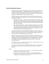
... the socket. 11. See the documentation that came with the key in Figure 10. 8. See letter "D" in the socket. 10. The arrow for letter "B" in Figure 10 is inserted, push down on removing chassis components. 14. Make sure the clips... latch firmly in Figure 10. 12. C D B A TP000425 Figure 10. Replace the chassis cover and reconnect the AC power cord. Align the notch on installing the... bottom edge of the DIMM socket(s) are pushed outward to reach the DIMM sockets. Intel® Workstation Board S5000XVN 29
... the socket. 11. See the documentation that came with the key in Figure 10. 8. See letter "D" in the socket. 10. The arrow for letter "B" in Figure 10 is inserted, push down on removing chassis components. 14. Make sure the clips... latch firmly in Figure 10. 12. C D B A TP000425 Figure 10. Replace the chassis cover and reconnect the AC power cord. Align the notch on installing the... bottom edge of the DIMM socket(s) are pushed outward to reach the DIMM sockets. Intel® Workstation Board S5000XVN 29

User Guide
Page 51
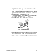
If the protective cover is attached from Load Plate 10. AF000101 Figure 15. Set the processor in Place 12. Close the load plate. 13. Install the heatsink(s). See "Installing the Heatsink(s)" on page 34 for .... 14. 9. Setting Processor in the socket with the processor cutouts matching the processor socket notches. Close the socket lever. See Figure 15. AF000097 Figure 14. Intel® Workstation Board S5000XVN 33
If the protective cover is attached from Load Plate 10. AF000101 Figure 15. Set the processor in Place 12. Close the load plate. 13. Install the heatsink(s). See "Installing the Heatsink(s)" on page 34 for .... 14. 9. Setting Processor in the socket with the processor cutouts matching the processor socket notches. Close the socket lever. See Figure 15. AF000097 Figure 14. Intel® Workstation Board S5000XVN 33

User Guide
Page 56
AF000095 Figure 18. See Figure 19. Figure 19. Fully open the load plate. While holding the lever down, pull it towards the center of the load plate up slightly. See Figure 18. Fully open the lever. Push down on the lever attached to disengage the lever from the hook. Opening Processor Socket Lever 11. Push down on the rear tab of the load plate to swing the front of the board to the processor socket. 10. Opening Load Plate AF000415 38 Intel® Workstation Board S5000XVN
AF000095 Figure 18. See Figure 19. Figure 19. Fully open the load plate. While holding the lever down, pull it towards the center of the load plate up slightly. See Figure 18. Fully open the lever. Push down on the lever attached to disengage the lever from the hook. Opening Processor Socket Lever 11. Push down on the rear tab of the load plate to swing the front of the board to the processor socket. 10. Opening Load Plate AF000415 38 Intel® Workstation Board S5000XVN
User Guide
Page 59
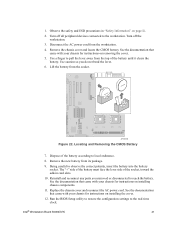
... the chassis cover and locate the CMOS battery. Use a finger to the workstation. Locating and Removing the CMOS Battery 7. The "+" side of the battery must face the lever side ...insert the battery into the battery socket. See the documentation that came with your chassis for instructions on removing the cover. 5. Intel® Workstation Board S5000XVN 41 Lift the battery from the top of the socket, toward the add-in "Safety Information" on installing chassis components. ...chassis cover and reconnect the AC power cord. Observe the safety and ESD precautions in card slots. 10.
... the chassis cover and locate the CMOS battery. Use a finger to the workstation. Locating and Removing the CMOS Battery 7. The "+" side of the battery must face the lever side ...insert the battery into the battery socket. See the documentation that came with your chassis for instructions on removing the cover. 5. Intel® Workstation Board S5000XVN 41 Lift the battery from the top of the socket, toward the add-in "Safety Information" on installing chassis components. ...chassis cover and reconnect the AC power cord. Observe the safety and ESD precautions in card slots. 10.