
User Guide
Page 7
... of the Server Board S3420GP. See "Additional Information and Software" for a link to navigate through the BIOS Setup screens, perform a BIOS update, and reset the password or CMOS. Chapter 3 provides instructions on the Title of the product, and product diagrams to... using the utilities shipped with the following Intel® Server Chassis: • Intel® Server Chassis SC5650UP (Intel® Server Board S3420GPLX and S3420GPLC) • Intel® Server Chassis SC5299DP/BRP (Intel® Server Board S3420GPLX and S3420GPLC) Intel®Server Board S3420GP User Guide vii ...
... of the Server Board S3420GP. See "Additional Information and Software" for a link to navigate through the BIOS Setup screens, perform a BIOS update, and reset the password or CMOS. Chapter 3 provides instructions on the Title of the product, and product diagrams to... using the utilities shipped with the following Intel® Server Chassis: • Intel® Server Chassis SC5650UP (Intel® Server Board S3420GPLX and S3420GPLC) • Intel® Server Chassis SC5299DP/BRP (Intel® Server Board S3420GPLX and S3420GPLC) Intel®Server Board S3420GP User Guide vii ...

User Guide
Page 9
...;Server Board S3420GP User Guide ix Diagnostics See also the Intel® Server Deployment Toolkit CD that were tested with your Intel® server For drivers For firmware and BIOS updates, or for BIOS recovery For diagnostics test software Use this product To make sure your system falls within the allowed power budget For software...
...;Server Board S3420GP User Guide ix Diagnostics See also the Intel® Server Deployment Toolkit CD that were tested with your Intel® server For drivers For firmware and BIOS updates, or for BIOS recovery For diagnostics test software Use this product To make sure your system falls within the allowed power budget For software...
User Guide
Page 15
... Socket Lever 44 Figure 17. 2U Reference Heatsink Assembly 45 Figure 18. Diagnostic LED Placement Diagram 51 Intel® Server Board S3420GP User Guide xv Intel® SAS Entry RAID Module 28 Figure 6. BMC Force Update Jumper 37 Figure 10. Lifting the Load Lever 42 Figure 12. Removing the PCI Riser Assembly from... Jumpers Location 24 Figure 4. Remove the Socket Protective Cover 43 Figure 14. Server Board Connector and Component Locations 22 Figure 3. CMOS Recovery Jumper 37 Figure 9. BIOS Recovery Jumper 35 Figure 7.
... Socket Lever 44 Figure 17. 2U Reference Heatsink Assembly 45 Figure 18. Diagnostic LED Placement Diagram 51 Intel® Server Board S3420GP User Guide xv Intel® SAS Entry RAID Module 28 Figure 6. BMC Force Update Jumper 37 Figure 10. Lifting the Load Lever 42 Figure 12. Removing the PCI Riser Assembly from... Jumpers Location 24 Figure 4. Remove the Socket Protective Cover 43 Figure 14. Server Board Connector and Component Locations 22 Figure 3. CMOS Recovery Jumper 37 Figure 9. BIOS Recovery Jumper 35 Figure 7.

User Guide
Page 25
... 3 Default Password Clear CMOS Clear 2 J1F5 3 Default CLEAR CMOS Jumper Name Pins J1A2: BMC Force Update 1-2 (Intel® Server Board S3420GPLX and S3420GPLC) 2-3 J1F2: Password Clear 1-2 2-3 J1F5: CMOS Clear 1-2 2-3 J1F3: BIOS Recovery 1-2 2-3 What will not boot with a recovery BIOS image. Enabled These pins should have a jumper in place for normal operation. Disabled (Default) BMC...
... 3 Default Password Clear CMOS Clear 2 J1F5 3 Default CLEAR CMOS Jumper Name Pins J1A2: BMC Force Update 1-2 (Intel® Server Board S3420GPLX and S3420GPLC) 2-3 J1F2: Password Clear 1-2 2-3 J1F5: CMOS Clear 1-2 2-3 J1F3: BIOS Recovery 1-2 2-3 What will not boot with a recovery BIOS image. Enabled These pins should have a jumper in place for normal operation. Disabled (Default) BMC...
User Guide
Page 35
... is pressed, all changes are saved and Setup is returned to upgrade the BIOS in flash memory. Setup Menu Key Use Description Save and Exit - Note: In the unlikely event a BIOS error occurs during the BIOS update process, you to where they were before was pressed without affecting any existing values... current BIOS settings and how to configure your computer at the end of the procedure. Boot the computer and press when you see the message: Press Key if you want to Press Table 5. Intel® Server Board S3420GP User Guide 33 The code and data in the BIOS Setup program...
... is pressed, all changes are saved and Setup is returned to upgrade the BIOS in flash memory. Setup Menu Key Use Description Save and Exit - Note: In the unlikely event a BIOS error occurs during the BIOS update process, you to where they were before was pressed without affecting any existing values... current BIOS settings and how to configure your computer at the end of the procedure. Boot the computer and press when you see the message: Press Key if you want to Press Table 5. Intel® Server Board S3420GP User Guide 33 The code and data in the BIOS Setup program...
User Guide
Page 36
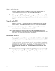
... readme file distributed with two high-pitched beeps. Caution: Do not power down the system and reboot. The system resets automatically when the BIOS update process is not initialized. To place the baseboard into recovery mode, move the boot option jumper (located on your settings, and exit Setup.... One high-pitched beep announces the start of short beeps. 34 Intel® Server Board S3420GP User Guide The entire process takes two to a temporary folder on the baseboard) to complete the upgrade. Note: ...
... readme file distributed with two high-pitched beeps. Caution: Do not power down the system and reboot. The system resets automatically when the BIOS update process is not initialized. To place the baseboard into recovery mode, move the boot option jumper (located on your settings, and exit Setup.... One high-pitched beep announces the start of short beeps. 34 Intel® Server Board S3420GP User Guide The entire process takes two to a temporary folder on the baseboard) to complete the upgrade. Note: ...
User Guide
Page 37
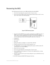
...8226; FVMAIN.FV • UEFI iFlash32 • *Rec.CAP • Startup.nsh (update accordingly to use proper *Rec.CAP file) 4. Move the BIOS recovery jumper at pins 2 and 3 to the original position, covering storage pins 1 and 2. 9. BIOS Recovery Jumper 3. Please note this platform does not support recovery from the AC power...spare location at J1F3 back to cover pins 1 and 2. Intel® Server Board S3420GP User Guide 35 Plug the system into the AC power source and power it up to the EFI SHELL. 6. Do NOT interrupt the BIOS POST during the first boot. Power down and unplug the ...
...8226; FVMAIN.FV • UEFI iFlash32 • *Rec.CAP • Startup.nsh (update accordingly to use proper *Rec.CAP file) 4. Move the BIOS recovery jumper at pins 2 and 3 to the original position, covering storage pins 1 and 2. 9. BIOS Recovery Jumper 3. Please note this platform does not support recovery from the AC power...spare location at J1F3 back to cover pins 1 and 2. Intel® Server Board S3420GP User Guide 35 Plug the system into the AC power source and power it up to the EFI SHELL. 6. Do NOT interrupt the BIOS POST during the first boot. Power down and unplug the ...
User Guide
Page 39
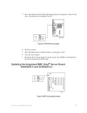
... from the default operating position (covering pins 1 and 2) to default position, covering pins 1 and 2. 6. Updating the Integrated BMC (Intel® Server Board S3420GPLX and S3420GPLC) BMC Force Update 2 J1A2 3 Default Enabled AF003291 Figure 9. 3. Move the jumper back to the reset / clear position (covering... 3). Close the server chassis. 7. Reconnect the AC power and power up the system. Wait five seconds. 5. BMC Force Update Jumper Intel® Server Board S3420GP User Guide 37 CMOS Clear 2 J1F5 3 Default CLEAR CMOS AF003182 Figure 8. CMOS Recovery Jumper 4. The...
... from the default operating position (covering pins 1 and 2) to default position, covering pins 1 and 2. 6. Updating the Integrated BMC (Intel® Server Board S3420GPLX and S3420GPLC) BMC Force Update 2 J1A2 3 Default Enabled AF003291 Figure 9. 3. Move the jumper back to the reset / clear position (covering... 3). Close the server chassis. 7. Reconnect the AC power and power up the system. Wait five seconds. 5. BMC Force Update Jumper Intel® Server Board S3420GP User Guide 37 CMOS Clear 2 J1F5 3 Default CLEAR CMOS AF003182 Figure 8. CMOS Recovery Jumper 4. The...

User Guide
Page 59
...POST Code Decoder 0xE7 O O O X X O O O Waiting for user input 0xE8 O O O X O X X X Checking password 0xE9 O O O X O X X O Entering BIOS setup 0xEA O O O X O X O X Flash Update 0xEE O O O X O O O X Calling Int 19. One beep unless silent boot is enabled. 0xEF O O O X O O O O Unrecoverable boot failure Runtime Phase / EFI Operating ... 0x35 X X O O X O X O Handing off control to the crisis recovery capsule 0x3F X X O O O O O O Unable to complete crisis recovery Intel® Server Board S3420GP User Guide 57
...POST Code Decoder 0xE7 O O O X X O O O Waiting for user input 0xE8 O O O X O X X X Checking password 0xE9 O O O X O X X O Entering BIOS setup 0xEA O O O X O X O X Flash Update 0xEE O O O X O O O X Calling Int 19. One beep unless silent boot is enabled. 0xEF O O O X O O O O Unrecoverable boot failure Runtime Phase / EFI Operating ... 0x35 X X O O X O X O Handing off control to the crisis recovery capsule 0x3F X X O O O O O O Unable to complete crisis recovery Intel® Server Board S3420GP User Guide 57
User Guide
Page 77
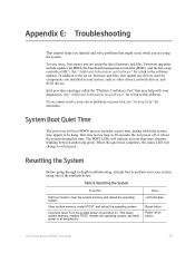
... in -depth troubleshooting, attempt first to the server firmware and files, also update any issue, first ensure you are using the latest firmware and files. System Boot Quiet Time The power-on button Intel® Server Board S3420GP User Guide 75 When the quiet time completes, the... during which the system may appear to all peripherals Press Reset button Power off and then on your own, see "Getting Help" for BIOS, the baseboard management controller (BMC), and the hot-swap controller (HSC). Appendix E: Troubleshooting This chapter helps you identify and solve problems ...
... in -depth troubleshooting, attempt first to the server firmware and files, also update any issue, first ensure you are using the latest firmware and files. System Boot Quiet Time The power-on button Intel® Server Board S3420GP User Guide 75 When the quiet time completes, the... during which the system may appear to all peripherals Press Reset button Power off and then on your own, see "Getting Help" for BIOS, the baseboard management controller (BMC), and the hot-swap controller (HSC). Appendix E: Troubleshooting This chapter helps you identify and solve problems ...


