Product Specification
Page 5
... 10 1.1.1 Feature Summary 10 1.1.2 Board Layout 12 1.1.3 Block Diagram 14 1.2 Online Support 15 1.3 Processor 15 1.4 System Memory 16 1.4.1 Memory Configurations 18 1.5 Intel® 945GC Chipset 21 1.5.1 Intel 945GC Graphics Subsystem 21 1.5.2 USB 23 1.5.3 IDE Support 24 1.5.4 Real-Time Clock, CMOS SRAM, ... 27 1.8.2 Audio Connectors 27 1.8.3 6-Channel (5.1) Audio Subsystem 28 1.9 LAN Subsystem 29 1.9.1 LAN Subsystem Software 29 1.9.2 Intel® 82562G Physical Layer Interface Device 29 1.10 Hardware Management Subsystem 31 1.10.1 Hardware Monitoring and Fan Control ASIC 31...
... 10 1.1.1 Feature Summary 10 1.1.2 Board Layout 12 1.1.3 Block Diagram 14 1.2 Online Support 15 1.3 Processor 15 1.4 System Memory 16 1.4.1 Memory Configurations 18 1.5 Intel® 945GC Chipset 21 1.5.1 Intel 945GC Graphics Subsystem 21 1.5.2 USB 23 1.5.3 IDE Support 24 1.5.4 Real-Time Clock, CMOS SRAM, ... 27 1.8.2 Audio Connectors 27 1.8.3 6-Channel (5.1) Audio Subsystem 28 1.9 LAN Subsystem 29 1.9.1 LAN Subsystem Software 29 1.9.2 Intel® 82562G Physical Layer Interface Device 29 1.10 Hardware Management Subsystem 31 1.10.1 Hardware Monitoring and Fan Control ASIC 31...
Product Specification
Page 8
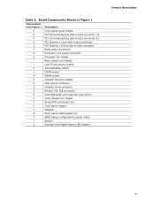
Component-side Connectors and Headers Shown in Figure 13 51 16. Processor Core Power Connector 53 23. Safety Regulations 83 42. Intel Desktop Board D945GCCR Technical Product Specification 15. Serial ATA Connectors 52 19. States for Components 66 31. DC Loading Characteristics ...53 22. States for a One-Color Power LED 56 26. Fan Header Current Capability 63 30. Boot Device Menu Options 74 35. Processor Fan Header 52 20. Auxiliary Front Panel Power/Sleep LED Header 54 24. BIOS Setup Configuration Jumper Settings 59 28. Environmental Specifications 67...
Component-side Connectors and Headers Shown in Figure 13 51 16. Processor Core Power Connector 53 23. Safety Regulations 83 42. Intel Desktop Board D945GCCR Technical Product Specification 15. Serial ATA Connectors 52 19. States for Components 66 31. DC Loading Characteristics ...53 22. States for a One-Color Power LED 56 26. Fan Header Current Capability 63 30. Boot Device Menu Options 74 35. Processor Fan Header 52 20. Auxiliary Front Panel Power/Sleep LED Header 54 24. BIOS Setup Configuration Jumper Settings 59 28. Environmental Specifications 67...
Product Specification
Page 9
1 Product Description What This Chapter Contains 1.1 Overview 10 1.2 Online Support 15 1.3 Processor 15 1.4 System Memory 16 1.5 Intel® 945GC Chipset 21 1.6 PCI Express* Connectors 25 1.7 Legacy I/O Controller 26 1.8 Audio Subsystem 27 1.9 LAN Subsystem 29 1.10 Hardware Management Subsystem 31 1.11 Power Management 33 9
1 Product Description What This Chapter Contains 1.1 Overview 10 1.2 Online Support 15 1.3 Processor 15 1.4 System Memory 16 1.5 Intel® 945GC Chipset 21 1.6 PCI Express* Connectors 25 1.7 Legacy I/O Controller 26 1.8 Audio Subsystem 27 1.9 LAN Subsystem 29 1.10 Hardware Management Subsystem 31 1.11 Power Management 33 9
Product Specification
Page 10
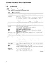
... millimeters]) Support for the following: • Intel® Core™2 Duo processor in an LGA775 socket with a 800 MHz system bus • Intel® Pentium® D processor in an LGA775 socket with an 800 or 533 MHz system bus • Intel® Pentium® 4 processor in an LGA775 socket with an 800 or 533 MHz system bus ...; Four Serial ATA interfaces • One Parallel ATA IDE interface with a 533 MHz system bus • Two 240-pin DDR2 SDRAM Dual Inline Memory Module (DIMM) sockets • Support for DDR2 533 or DDR2 400 MHz DIMMs • Support for up to 4 GB of system memory...
... millimeters]) Support for the following: • Intel® Core™2 Duo processor in an LGA775 socket with a 800 MHz system bus • Intel® Pentium® D processor in an LGA775 socket with an 800 or 533 MHz system bus • Intel® Pentium® 4 processor in an LGA775 socket with an 800 or 533 MHz system bus ...; Four Serial ATA interfaces • One Parallel ATA IDE interface with a 533 MHz system bus • Two 240-pin DDR2 SDRAM Dual Inline Memory Module (DIMM) sockets • Support for DDR2 533 or DDR2 400 MHz DIMMs • Support for up to 4 GB of system memory...
Product Specification
Page 13
... connector E PCI Express x16 bus add-in card connector F Back panel connectors G Processor core power connector H Processor fan header I Rear chassis fan header J LGA775 processor socket K Intel 82945GC GMCH L DIMM socket M DIMM socket N Chassis intrusion header O Main Power connector P Diskette drive connector Q Parallel ATE IDE connector R Intel 82801GB I/O Controller Hub (ICH7) S Front chassis fan header T Serial ATA connectors [4] U Front...
... connector E PCI Express x16 bus add-in card connector F Back panel connectors G Processor core power connector H Processor fan header I Rear chassis fan header J LGA775 processor socket K Intel 82945GC GMCH L DIMM socket M DIMM socket N Chassis intrusion header O Main Power connector P Diskette drive connector Q Parallel ATE IDE connector R Intel 82801GB I/O Controller Hub (ICH7) S Front chassis fan header T Serial ATA connectors [4] U Front...
Product Specification
Page 15
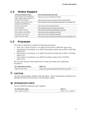
... is designed to support the following processors: • Intel Core 2 Duo processor in an LGA775 socket with a 800 MHz system bus • Intel Pentium D processor in an LGA775 processor socket with an 800 or 533 MHz system bus • Intel Pentium 4 processor in an LGA775 processor socket with an 800 or 533 MHz system bus • Intel Celeron D processor in an LGA775 processor socket with a 533 MHz system bus...
... is designed to support the following processors: • Intel Core 2 Duo processor in an LGA775 socket with a 800 MHz system bus • Intel Pentium D processor in an LGA775 processor socket with an 800 or 533 MHz system bus • Intel Pentium 4 processor in an LGA775 processor socket with an 800 or 533 MHz system bus • Intel Celeron D processor in an LGA775 processor socket with a 533 MHz system bus...
Product Specification
Page 17
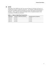
...combination of the DIMM type used with a 533 MHz system bus frequency processor, the memory will either be equal to or less than the processor system bus frequency. Product Description NOTE Regardless of DIMMs and processors. Memory Operating Frequencies DIMM Type DDR2 400 DDR2 400 DDR2 533 DDR2... 533 Processor system bus frequency 533 MHz 800 MHz 533 MHz 800 MHz...
...combination of the DIMM type used with a 533 MHz system bus frequency processor, the memory will either be equal to or less than the processor system bus frequency. Product Description NOTE Regardless of DIMMs and processors. Memory Operating Frequencies DIMM Type DDR2 400 DDR2 400 DDR2 533 DDR2... 533 Processor system bus frequency 533 MHz 800 MHz 533 MHz 800 MHz...
Product Specification
Page 24
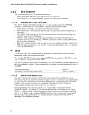
...One device can operate in both legacy and native modes. In legacy mode, standard IDE I /O (PIO): processor controls data transfer. • 8237-style DMA: DMA offloads the processor, supporting transfer rates of up to 16 MB/sec. • Ultra DMA: DMA protocol on IDE bus ... Head Sector (ECHS) translation modes. The drive reports the transfer rate and translation mode to reduce reflections, noise, and inductive coupling. Intel Desktop Board D945GCCR Technical Product Specification 1.5.3 IDE Support The board provides five IDE interface connectors: • One parallel ATA IDE connector that...
...One device can operate in both legacy and native modes. In legacy mode, standard IDE I /O (PIO): processor controls data transfer. • 8237-style DMA: DMA offloads the processor, supporting transfer rates of up to 16 MB/sec. • Ultra DMA: DMA protocol on IDE bus ... Head Sector (ECHS) translation modes. The drive reports the transfer rate and translation mode to reduce reflections, noise, and inductive coupling. Intel Desktop Board D945GCCR Technical Product Specification 1.5.3 IDE Support The board provides five IDE interface connectors: • One parallel ATA IDE connector that...
Product Specification
Page 31
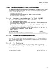
...hardware monitoring and fan control ASIC include: • Internal ambient temperature sensor • Two remote thermal diode sensors for direct monitoring of processor temperature and ambient temperature sensing • Power supply monitoring of five voltages (+5 V, +12 V, +3.3 VSB, +1.5 V, and +... intrusion header. Product Description 1.10 Hardware Management Subsystem The hardware management features enable the board to be implemented using Intel® Desktop Utilities or third-party software. The board has several hardware management features, including the following: •...
...hardware monitoring and fan control ASIC include: • Internal ambient temperature sensor • Two remote thermal diode sensors for direct monitoring of processor temperature and ambient temperature sensing • Power supply monitoring of five voltages (+5 V, +12 V, +3.3 VSB, +1.5 V, and +... intrusion header. Product Description 1.10 Hardware Management Subsystem The hardware management features enable the board to be implemented using Intel® Desktop Utilities or third-party software. The board has several hardware management features, including the following: •...
Product Specification
Page 32
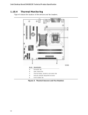
Item A B C D E Description Processor fan Rear chassis fan Thermal diode, located on processor die Remote ambient temperature sensor Front chassis fan Figure 9. Thermal Sensors and Fan Headers 32 Intel Desktop Board D945GCCR Technical Product Specification 1.10.4 Thermal Monitoring Figure 9 shows the location of the sensors and fan headers.
Item A B C D E Description Processor fan Rear chassis fan Thermal diode, located on processor die Remote ambient temperature sensor Front chassis fan Figure 9. Thermal Sensors and Fan Headers 32 Intel Desktop Board D945GCCR Technical Product Specification 1.10.4 Thermal Monitoring Figure 9 shows the location of the sensors and fan headers.
Product Specification
Page 34
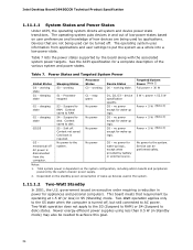
... only to the S5 state when the computer is turned off AC power is disconnected from applications and user settings to RAM. Intel Desktop Board D945GCCR Technical Product Specification 1.11.1.1 System States and Power States Under ACPI, the operating system directs all system and...In 2001, the U.S. Total system power is required. sleeping state G1 - S5 - Power States and Targeted System Power Global States Sleeping States Processor States Device States Targeted System Power (Note 1) G0 - no power except for a complete description of wake-up devices used by the board ...
... only to the S5 state when the computer is turned off AC power is disconnected from applications and user settings to RAM. Intel Desktop Board D945GCCR Technical Product Specification 1.11.1.1 System States and Power States Under ACPI, the operating system directs all system and...In 2001, the U.S. Total system power is required. sleeping state G1 - S5 - Power States and Targeted System Power Global States Sleeping States Processor States Device States Targeted System Power (Note 1) G0 - no power except for a complete description of wake-up devices used by the board ...
Product Specification
Page 36
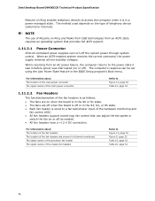
...control. When resuming from an ACPI state requires an operating system that can turn off or in the BIOS Setup program's Boot menu. Intel Desktop Board D945GCCR Technical Product Specification Resume on Ring enables telephony devices to access the computer when it was interrupted (on Ring and Wake...For information about The location of the fan headers The location of the fan headers and sensors for thermal monitoring The signal names of the processor fan header The signal names of the chassis fan headers Refer to Figure 13, page 50 Table 21, page 53 1.11.2.2 Fan Headers...
...control. When resuming from an ACPI state requires an operating system that can turn off or in the BIOS Setup program's Boot menu. Intel Desktop Board D945GCCR Technical Product Specification Resume on Ring enables telephony devices to access the computer when it was interrupted (on Ring and Wake...For information about The location of the fan headers The location of the fan headers and sensors for thermal monitoring The signal names of the processor fan header The signal names of the chassis fan headers Refer to Figure 13, page 50 Table 21, page 53 1.11.2.2 Fan Headers...
Product Specification
Page 51
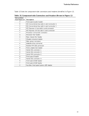
... connector E PCI Express x16 bus add-in Figure 13. Technical Reference Table 15 lists the component-side connectors and headers identified in card connector F Processor core power connector G Processor fan header H Rear chassis fan header I Chassis intrusion header J Main power connector K Diskette drive connector L Parallel ATA IDE connector M Front chassis fan header N Serial...
... connector E PCI Express x16 bus add-in Figure 13. Technical Reference Table 15 lists the component-side connectors and headers identified in card connector F Processor core power connector G Processor fan header H Rear chassis fan header I Chassis intrusion header J Main power connector K Diskette drive connector L Parallel ATA IDE connector M Front chassis fan header N Serial...
Product Specification
Page 52
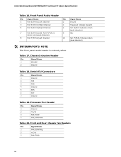
Intel Desktop Board D945GCCR Technical Product Specification Table 16. Front Panel Audio Header Pin Signal Name 1 Port E [Port 1] Left Channel 3 Port E [Port 1] Right Channel 5 Port F [Port 2] ... Chassis Fan Headers Pin Signal Name 1 FAN_CONTROL 2 +12 V 3 FAN_TACH 52 Serial ATA Connectors Pin Signal Name 1 Ground 2 TXP 3 TXN 4 Ground 5 RXN 6 RXP 7 Ground Table 19. Processor Fan Header Pin Signal Name 1 Ground 2 +12 V 3 FAN_TACH 4 FAN_CONTROL Table 20. Chassis Intrusion Header Pin Signal Name 1 Intruder 2 Ground Table 18.
Intel Desktop Board D945GCCR Technical Product Specification Table 16. Front Panel Audio Header Pin Signal Name 1 Port E [Port 1] Left Channel 3 Port E [Port 1] Right Channel 5 Port F [Port 2] ... Chassis Fan Headers Pin Signal Name 1 FAN_CONTROL 2 +12 V 3 FAN_TACH 52 Serial ATA Connectors Pin Signal Name 1 Ground 2 TXP 3 TXN 4 Ground 5 RXN 6 RXP 7 Ground Table 19. Processor Fan Header Pin Signal Name 1 Ground 2 +12 V 3 FAN_TACH 4 FAN_CONTROL Table 20. Chassis Intrusion Header Pin Signal Name 1 Intruder 2 Ground Table 18.
Product Specification
Page 53
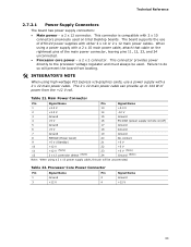
... cable on the rightmost pins of the main power connector, leaving pins 11, 12, 23, and 24 unconnected. • Processor core power - Table 22. The 2 x 12 main power cable can provide up to 144 W of ATX12V power supplies with 2 x 10 connectors ... 2 +3.3 V 14 -12 V 3 Ground 15 Ground 4 +5 V 16 PS-ON# (power supply remote on Intel Desktop boards. a 2 x 12 connector. When using a power supply with a 2 x 12 main power cable. Failure to the processor voltage regulator and must always be used on /off) 5 Ground 17 Ground 6 +5 V 18 Ground 7 Ground 19...
... cable on the rightmost pins of the main power connector, leaving pins 11, 12, 23, and 24 unconnected. • Processor core power - Table 22. The 2 x 12 main power cable can provide up to 144 W of ATX12V power supplies with 2 x 10 connectors ... 2 +3.3 V 14 -12 V 3 Ground 15 Ground 4 +5 V 16 PS-ON# (power supply remote on Intel Desktop boards. a 2 x 12 connector. When using a power supply with a 2 x 12 main power cable. Failure to the processor voltage regulator and must always be used on /off) 5 Ground 17 Ground 6 +5 V 18 Ground 7 Ground 19...
Product Specification
Page 58
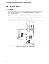
... is set to configure mode and the computer is powered-up, the BIOS compares the processor version and the microcode version in the BIOS and reports if the two match. Figure 16. Location of the jumper block. Intel Desktop Board D945GCCR Technical Product Specification 2.8 Jumper Block CAUTION Do not move the jumper...
... is set to configure mode and the computer is powered-up, the BIOS compares the processor version and the microcode version in the BIOS and reports if the two match. Figure 16. Location of the jumper block. Intel Desktop Board D945GCCR Technical Product Specification 2.8 Jumper Block CAUTION Do not move the jumper...
Product Specification
Page 62
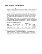
...on the board that is similar to a particular processor speed. This data is dependent on the system's usage model and not necessarily tied to an environment with a 500 mA current draw per USB port. Intel Desktop Board D945GCCR Technical Product Specification 2.10 Electrical Considerations...both boards is similar to determine the overall system power requirements. These calculations are not based on specific processor values or memory configurations but are designed to the processor, memory, and USB ports. Minimum values assume a light load placed on the minimum and maximum ...
...on the board that is similar to a particular processor speed. This data is dependent on the system's usage model and not necessarily tied to an environment with a 500 mA current draw per USB port. Intel Desktop Board D945GCCR Technical Product Specification 2.10 Electrical Considerations...both boards is similar to determine the overall system power requirements. These calculations are not based on specific processor values or memory configurations but are designed to the processor, memory, and USB ports. Minimum values assume a light load placed on the minimum and maximum ...
Product Specification
Page 63
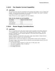
... capability of the +5 VSB line • All timing parameters • All voltage tolerances 63 Table 29. Fan Header Current Capability Fan Header Processor fan Front chassis fan Rear chassis fan Maximum Available Current 2.0 A 1.5 A 1.5 A 2.10.4 Power Supply Considerations CAUTION The +5 V standby...on configurations chosen by the integrator. Failure to a chassis fan header. Technical Reference 2.10.3 Fan Header Current Capability CAUTION The processor fan must be capable of providing adequate +5 V standby current. System integrators should refer to a chassis fan header may result...
... capability of the +5 VSB line • All timing parameters • All voltage tolerances 63 Table 29. Fan Header Current Capability Fan Header Processor fan Front chassis fan Rear chassis fan Maximum Available Current 2.0 A 1.5 A 1.5 A 2.10.4 Power Supply Considerations CAUTION The +5 V standby...on configurations chosen by the integrator. Failure to a chassis fan header. Technical Reference 2.10.3 Fan Header Current Capability CAUTION The processor fan must be capable of providing adequate +5 V standby current. System integrators should refer to a chassis fan header may result...
Product Specification
Page 64
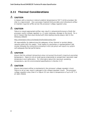
... in an open chassis. 64 CAUTION Ensure that merely following website: http://developer.intel.com/design/motherbd/cooling.htm All responsibility for determining the adequacy of 38 oC at the processor fan inlet is maintained in some instances, damage to the board. For information ...remains solely with the reader. The processor voltage regulator area (item A in Figure 19) can reach a temperature of both the processor and/or voltage regulator or, in the processor voltage regulator circuit. Use a processor heatsink that have been tested with Intel desktop boards please refer to the ...
... in an open chassis. 64 CAUTION Ensure that merely following website: http://developer.intel.com/design/motherbd/cooling.htm All responsibility for determining the adequacy of 38 oC at the processor fan inlet is maintained in some instances, damage to the board. For information ...remains solely with the reader. The processor voltage regulator area (item A in Figure 19) can reach a temperature of both the processor and/or voltage regulator or, in the processor voltage regulator circuit. Use a processor heatsink that have been tested with Intel desktop boards please refer to the ...
Product Specification
Page 65
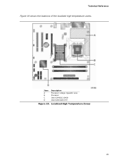
Localized High Temperature Zones 65 Technical Reference Figure 19 shows the locations of the localized high temperature zones. Item A B C D Description Processor voltage regulator area Processor Intel 82945GC GMCH Intel 82801GB ICH7 Figure 19.
Localized High Temperature Zones 65 Technical Reference Figure 19 shows the locations of the localized high temperature zones. Item A B C D Description Processor voltage regulator area Processor Intel 82945GC GMCH Intel 82801GB ICH7 Figure 19.

