
Product Specification
Page 5
... 1.1.2 Board Layout 12 1.1.3 Block Diagram 14 1.2 Online Support 15 1.3 Processor 15 1.4 System Memory 16 1.4.1 Memory Configurations 18 1.5 Intel® 945GC Chipset 21 1.5.1 Intel 945GC Graphics Subsystem 21 1.5.2 USB 23 1.5.3 IDE Support 24 1.5.4 Real-Time Clock, CMOS SRAM, and Battery 25 1.6 PCI Express* Connectors 25 1.7 Legacy I/O Controller 26 1.7.1 Serial Port 26 1.7.2 Parallel Port 26 1.7.3 Diskette Drive Controller 26 1.7.4 Keyboard and Mouse Interface 26 1.8 Audio Subsystem 27 1.8.1 Audio Subsystem Software 27 1.8.2 Audio Connectors 27 1.8.3 6-Channel (5.1) Audio...
... 1.1.2 Board Layout 12 1.1.3 Block Diagram 14 1.2 Online Support 15 1.3 Processor 15 1.4 System Memory 16 1.4.1 Memory Configurations 18 1.5 Intel® 945GC Chipset 21 1.5.1 Intel 945GC Graphics Subsystem 21 1.5.2 USB 23 1.5.3 IDE Support 24 1.5.4 Real-Time Clock, CMOS SRAM, and Battery 25 1.6 PCI Express* Connectors 25 1.7 Legacy I/O Controller 26 1.7.1 Serial Port 26 1.7.2 Parallel Port 26 1.7.3 Diskette Drive Controller 26 1.7.4 Keyboard and Mouse Interface 26 1.8 Audio Subsystem 27 1.8.1 Audio Subsystem Software 27 1.8.2 Audio Connectors 27 1.8.3 6-Channel (5.1) Audio...
Product Specification
Page 6
... PCI IDE Support 71 3.4 System Management BIOS (SMBIOS 71 3.5 BIOS Updates 72 3.5.1 Language Support 72 3.5.2 Custom Splash Screen 72 3.6 Legacy USB Support 73 3.7 Boot Options 73 3.7.1 CD-ROM Boot 73 3.7.2 Network Boot 73 3.7.3 Booting Without Attached Devices 74 3.7.4 Changing the Default Boot Device During POST 74 3.8 Adjusting Boot Speed 75 3.8.1 Peripheral Selection and Configuration 75 3.8.2 BIOS Boot Optimizations 75 3.9 BIOS Security Features 76 4 Error Messages and Beep Codes 4.1 Speaker 77 4.2 BIOS Beep Codes 77 4.3 BIOS Error Messages 77 4.4 Port 80h POST Codes...
... PCI IDE Support 71 3.4 System Management BIOS (SMBIOS 71 3.5 BIOS Updates 72 3.5.1 Language Support 72 3.5.2 Custom Splash Screen 72 3.6 Legacy USB Support 73 3.7 Boot Options 73 3.7.1 CD-ROM Boot 73 3.7.2 Network Boot 73 3.7.3 Booting Without Attached Devices 74 3.7.4 Changing the Default Boot Device During POST 74 3.8 Adjusting Boot Speed 75 3.8.1 Peripheral Selection and Configuration 75 3.8.2 BIOS Boot Optimizations 75 3.9 BIOS Security Features 76 4 Error Messages and Beep Codes 4.1 Speaker 77 4.2 BIOS Beep Codes 77 4.3 BIOS Error Messages 77 4.4 Port 80h POST Codes...
Product Specification
Page 7
... Panel USB Headers 57 16. Localized High Temperature Zones 65 Tables 1. Supported Memory Configurations 16 4. Contents 5 Regulatory Compliance and Battery Disposal Information 5.1 Regulatory Compliance 83 5.1.1 Safety Regulations 83 5.1.2 European Union Declaration of the Standby Power Indicator LED 39 11. Single Channel (Asymmetric) Mode Configuration with One DIMM .......... 19 6. Component-side Connectors and Headers 50 14. Board Components Shown in Figure 1 13 3. LAN Connector LED States 30 6. LAN Connector LED Locations 30 9. Thermal Sensors and Fan Headers...
... Panel USB Headers 57 16. Localized High Temperature Zones 65 Tables 1. Supported Memory Configurations 16 4. Contents 5 Regulatory Compliance and Battery Disposal Information 5.1 Regulatory Compliance 83 5.1.1 Safety Regulations 83 5.1.2 European Union Declaration of the Standby Power Indicator LED 39 11. Single Channel (Asymmetric) Mode Configuration with One DIMM .......... 19 6. Component-side Connectors and Headers 50 14. Board Components Shown in Figure 1 13 3. LAN Connector LED States 30 6. LAN Connector LED Locations 30 9. Thermal Sensors and Fan Headers...
Product Specification
Page 8
... and User Password Functions 76 36. Safety Regulations 83 42. Auxiliary Front Panel Power/Sleep LED Header 54 24. Fan Header Current Capability 63 30. States for a Two-Color Power LED 56 27. Lead-Free Board Markings 88 43. Boot Device Menu Options 74 35. Serial ATA Connectors 52 19. DC Loading Characteristics 62 29. BIOS Setup Program Function Keys 70 34. Processor Fan Header 52 20. Thermal Considerations for Components 66 31. Front Panel Audio Header 52 17. Beep Codes...
... and User Password Functions 76 36. Safety Regulations 83 42. Auxiliary Front Panel Power/Sleep LED Header 54 24. Fan Header Current Capability 63 30. States for a Two-Color Power LED 56 27. Lead-Free Board Markings 88 43. Boot Device Menu Options 74 35. Serial ATA Connectors 52 19. DC Loading Characteristics 62 29. BIOS Setup Program Function Keys 70 34. Processor Fan Header 52 20. Thermal Considerations for Components 66 31. Front Panel Audio Header 52 17. Beep Codes...
Product Specification
Page 10
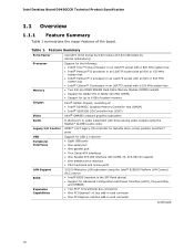
... of the board. Intel Desktop Board D945GCCR Technical Product Specification 1.1 Overview 1.1.1 Feature Summary Table 1 summarizes the major features of : • Intel® 82945GC Graphics Memory Controller Hub (GMCH) • Intel® 82801GB I/O Controller Hub (ICH7) Intel® GMA950 onboard graphics subsystem 6-channel (5.1) audio subsystem with three analog audio outputs using the Realtek* ALC883 audio codec SMSC* 5127 legacy I/O controller for diskette drive, serial, parallel, and PS/2* ports Support for USB 2.0 devices • Eight USB ports • One serial port •...
... of the board. Intel Desktop Board D945GCCR Technical Product Specification 1.1 Overview 1.1.1 Feature Summary Table 1 summarizes the major features of : • Intel® 82945GC Graphics Memory Controller Hub (GMCH) • Intel® 82801GB I/O Controller Hub (ICH7) Intel® GMA950 onboard graphics subsystem 6-channel (5.1) audio subsystem with three analog audio outputs using the Realtek* ALC883 audio codec SMSC* 5127 legacy I/O controller for diskette drive, serial, parallel, and PS/2* ports Support for USB 2.0 devices • Eight USB ports • One serial port •...
Product Specification
Page 16
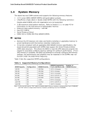
... • DDR2 533 or DDR2 400 MHz SDRAM DIMMs NOTES • Remove the PCI Express x16 video card before installing or upgrading memory to correctly configure the memory settings, but performance and reliability may be populated with x16 organization are not supported. • 2 GB maximum total system memory. Table 3. Refer to Section 2.1.1 on page 41 for optimum performance. If nonSPD memory is installed, the BIOS will attempt...
... • DDR2 533 or DDR2 400 MHz SDRAM DIMMs NOTES • Remove the PCI Express x16 video card before installing or upgrading memory to correctly configure the memory settings, but performance and reliability may be populated with x16 organization are not supported. • 2 GB maximum total system memory. Table 3. Refer to Section 2.1.1 on page 41 for optimum performance. If nonSPD memory is installed, the BIOS will attempt...

Product Specification
Page 21
...; 8, 16,and 32 bit color ⎯ Optimized 256-bit BLT engine ⎯ Color space conversion ⎯ Anti-aliased lines 21 The component also provides integrated graphics capabilities supporting 3D, 2D and display capabilities. When a PCI Express x16 add-in card is installed, the GMA950 graphics controller is used, or a PCI Express x16 add-in card can be used by the chipset Refer to the CPU, memory, PCI Express, and the DMI...
...; 8, 16,and 32 bit color ⎯ Optimized 256-bit BLT engine ⎯ Color space conversion ⎯ Anti-aliased lines 21 The component also provides integrated graphics capabilities supporting 3D, 2D and display capabilities. When a PCI Express x16 add-in card is installed, the GMA950 graphics controller is used, or a PCI Express x16 add-in card can be used by the chipset Refer to the CPU, memory, PCI Express, and the DMI...

Product Specification
Page 22
... installed. Intel Desktop Board D945GCCR Technical Product Specification • Video ⎯ Hardware motion compensation for MPEG2 ⎯ Software DVD at 30 fps full screen • Display ⎯ Integrated 24-bit 400 MHz RAMDAC ⎯ Up to 2048 x 1536 at 75 Hz refresh (QXGA) ⎯ DDC2B compliant interface with Advanced Digital Display 2 or 2+ (ADD2/ADD2+) cards, support for TV-out/TV-in the BIOS Setup program) for compatibility...
... installed. Intel Desktop Board D945GCCR Technical Product Specification • Video ⎯ Hardware motion compensation for MPEG2 ⎯ Software DVD at 30 fps full screen • Display ⎯ Integrated 24-bit 400 MHz RAMDAC ⎯ Up to 2048 x 1536 at 75 Hz refresh (QXGA) ⎯ DDC2B compliant interface with Advanced Digital Display 2 or 2+ (ADD2/ADD2+) cards, support for TV-out/TV-in the BIOS Setup program) for compatibility...
Product Specification
Page 29
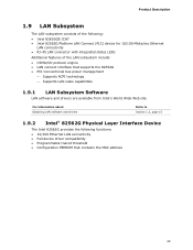
... device driver compatibility • Programmable transit threshold • Configuration EEPROM that supports the 82562G • PCI Conventional bus power management ⎯ Supports ACPI technology ⎯ Supports LAN wake capabilities 1.9.1 LAN Subsystem Software LAN software and drivers are available from Intel's World Wide Web site. For information about Obtaining LAN software and drivers Refer to Section 1.2, page 15 1.9.2 Intel® 82562G Physical Layer Interface Device The Intel 82562G provides the following : • Intel 82801GB ICH7 • Intel 82562G Platform LAN Connect...
... device driver compatibility • Programmable transit threshold • Configuration EEPROM that supports the 82562G • PCI Conventional bus power management ⎯ Supports ACPI technology ⎯ Supports LAN wake capabilities 1.9.1 LAN Subsystem Software LAN software and drivers are available from Intel's World Wide Web site. For information about Obtaining LAN software and drivers Refer to Section 1.2, page 15 1.9.2 Intel® 82562G Physical Layer Interface Device The Intel 82562G provides the following : • Intel 82801GB ICH7 • Intel 82562G Platform LAN Connect...

Product Specification
Page 35
...... The board provides several power management hardware features, including: • Power connector • Fan headers • LAN wake capabilities • Instantly Available PC technology • Resume on the wake devices supported and manufacturing options. LAN ...from the +5 V standby line. 35 Setting this state S1, S3, S4, S5 (Note) Modem (back panel Serial Port A) PME# signal S1, S3 S1, S3, S4, S5 (Note) Power switch S1, S3, S4, S5 PS/2 devices S1...
...... The board provides several power management hardware features, including: • Power connector • Fan headers • LAN wake capabilities • Instantly Available PC technology • Resume on the wake devices supported and manufacturing options. LAN ...from the +5 V standby line. 35 Setting this state S1, S3, S4, S5 (Note) Modem (back panel Serial Port A) PME# signal S1, S3 S1, S3, S4, S5 (Note) Power switch S1, S3, S4, S5 PS/2 devices S1...
Product Specification
Page 36
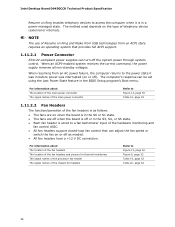
... fan headers support closed-loop fan control that provides full ACPI support. 1.11.2.1 Power Connector ATX12V-compliant power supplies can be set using the Last Power State feature in the BIOS Setup program's Boot menu. The method used depends on Ring and Wake from USB technologies from an AC power failure, the computer returns to the power state it is as needed. • All fan headers have a +12 V DC connection. Intel Desktop Board D945GCCR Technical Product Specification Resume on Ring enables telephony devices to access...
... fan headers support closed-loop fan control that provides full ACPI support. 1.11.2.1 Power Connector ATX12V-compliant power supplies can be set using the Last Power State feature in the BIOS Setup program's Boot menu. The method used depends on Ring and Wake from USB technologies from an AC power failure, the computer returns to the power state it is as needed. • All fan headers have a +12 V DC connection. Intel Desktop Board D945GCCR Technical Product Specification Resume on Ring enables telephony devices to access...
Product Specification
Page 45
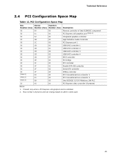
... a PCI Express x16 graphics card is dynamic and can change based on add-in cards used. 45 PCI Configuration Space Map Bus Device Function Number (hex) Number (hex) Number (hex) Description 00 00 00 Memory controller of Intel 82945GC component 00 01 00 PCI Express x16 graphics port (Note 1) 00 02 00 Integrated graphics controller 00 1B 00 High Definition Audio Controller 00 1C 00 PCI Express port 1 00 1D 00 USB UHCI controller 1 00 1D 01 USB UHCI controller...
... a PCI Express x16 graphics card is dynamic and can change based on add-in cards used. 45 PCI Configuration Space Map Bus Device Function Number (hex) Number (hex) Number (hex) Description 00 00 00 Memory controller of Intel 82945GC component 00 01 00 PCI Express x16 graphics port (Note 1) 00 02 00 Integrated graphics controller 00 1B 00 High Definition Audio Controller 00 1C 00 PCI Express port 1 00 1D 00 USB UHCI controller 1 00 1D 01 USB UHCI controller...
Product Specification
Page 48
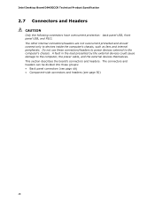
Intel Desktop Board D945GCCR Technical Product Specification 2.7 Connectors and Headers CAUTION Only the following connectors have overcurrent protection: back panel USB, front panel USB, and PS/2. A fault in the load presented by the external devices could cause damage to devices inside the computer's chassis, such as fans and internal peripherals. The other internal connectors/headers are not overcurrent protected and should connect only to the computer, the power cable, and the external devices themselves. Do...
Intel Desktop Board D945GCCR Technical Product Specification 2.7 Connectors and Headers CAUTION Only the following connectors have overcurrent protection: back panel USB, front panel USB, and PS/2. A fault in the load presented by the external devices could cause damage to devices inside the computer's chassis, such as fans and internal peripherals. The other internal connectors/headers are not overcurrent protected and should connect only to the computer, the power cable, and the external devices themselves. Do...

Product Specification
Page 69
The SPI Flash contains the BIOS Setup program, POST, the PCI auto-configuration utility, and Plug and Play support. The BIOS displays a message during POST identifying the type of BIOS Features What This Chapter Contains 3.1 Introduction 69 3.2 BIOS Flash Memory Organization 70 3.3 Resource Configuration 70 3.4 System Management BIOS (SMBIOS 71 3.5 BIOS Updates 72 3.6 Legacy USB Support 73 3.7 Boot Options 73 3.8 Adjusting Boot Speed 75 3.9 BIOS Security Features 76 3.1 Introduction The boards use an Intel BIOS that is set to view and change the BIOS settings for the computer....
The SPI Flash contains the BIOS Setup program, POST, the PCI auto-configuration utility, and Plug and Play support. The BIOS displays a message during POST identifying the type of BIOS Features What This Chapter Contains 3.1 Introduction 69 3.2 BIOS Flash Memory Organization 70 3.3 Resource Configuration 70 3.4 System Management BIOS (SMBIOS 71 3.5 BIOS Updates 72 3.6 Legacy USB Support 73 3.7 Boot Options 73 3.8 Adjusting Boot Speed 75 3.9 BIOS Security Features 76 3.1 Introduction The boards use an Intel BIOS that is set to view and change the BIOS settings for the computer....
Product Specification
Page 70
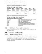
...Main Advanced Displays processor and memory configuration Configures advanced features available through the chipset Security Sets passwords and security features Power Boot Configures power management features and power supply controls Selects boot options Exit Saves or discards changes to Setup program options Table 33 lists the function keys available for the current menu Save the current values and exits the BIOS Setup program Exits the menu 3.2 BIOS Flash Memory Organization The Serial Peripheral Interface Flash Memory (SPI Flash) includes a 4 Mbit (512 KB) flash memory device...
...Main Advanced Displays processor and memory configuration Configures advanced features available through the chipset Security Sets passwords and security features Power Boot Configures power management features and power supply controls Selects boot options Exit Saves or discards changes to Setup program options Table 33 lists the function keys available for the current menu Save the current values and exits the BIOS Setup program Exits the menu 3.2 BIOS Flash Memory Organization The Serial Peripheral Interface Flash Memory (SPI Flash) includes a 4 Mbit (512 KB) flash memory device...
Product Specification
Page 71
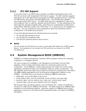
... supports second-generation SATA drives. To use SMBIOS. Using SMBIOS, a system administrator can override the auto-configuration options by specifying manual configuration in the BIOS Setup program, the BIOS automatically sets up to use ATA-66/100 features the following SMBIOS information: • BIOS data, such as the BIOS revision level • Fixed-system data, such as peripherals, serial numbers, and asset tags • Resource data, such as memory size...
... supports second-generation SATA drives. To use SMBIOS. Using SMBIOS, a system administrator can override the auto-configuration options by specifying manual configuration in the BIOS Setup program, the BIOS automatically sets up to use ATA-66/100 features the following SMBIOS information: • BIOS data, such as the BIOS revision level • Fixed-system data, such as peripherals, serial numbers, and asset tags • Resource data, such as memory size...
Product Specification
Page 73
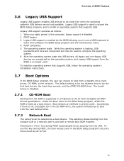
... boot device, the hard drive second, and the ATAPI CD-ROM third. To use a USB keyboard to enter and configure the BIOS Setup program and the maintenance menu. 4. Accordingly, if there is no longer used. Legacy USB support is used to access the BIOS Setup program, and to install an operating system that supports USB, follow the operating system's installation instructions. 3.7 Boot Options In the BIOS Setup program, the user can be selected as follows: 1. The operating system loads. Pressing the key during POST...
... boot device, the hard drive second, and the ATAPI CD-ROM third. To use a USB keyboard to enter and configure the BIOS Setup program and the maintenance menu. 4. Accordingly, if there is no longer used. Legacy USB support is used to access the BIOS Setup program, and to install an operating system that supports USB, follow the operating system's installation instructions. 3.7 Boot Options In the BIOS Setup program, the user can be selected as follows: 1. The operating system loads. Pressing the key during POST...
Product Specification
Page 76
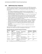
... is set , users can enter either the supervisor password or the user password to access Setup. This is the user mode. • If only the supervisor password is not displayed on the screen. Intel Desktop Board D945GCCR Technical Product Specification 3.9 BIOS Security Features The BIOS includes security features that restrict access to the BIOS Setup program and who can change all Setup options. This is the supervisor mode. • The user password gives restricted access to Enter Setup None Password During Boot None...
... is set , users can enter either the supervisor password or the user password to access Setup. This is the user mode. • If only the supervisor password is not displayed on the screen. Intel Desktop Board D945GCCR Technical Product Specification 3.9 BIOS Security Features The BIOS includes security features that restrict access to the BIOS Setup program and who can change all Setup options. This is the supervisor mode. • The user password gives restricted access to Enter Setup None Password During Boot None...
Product Specification
Page 78
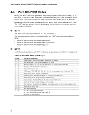
... or no useful memory detected. Displaying the POST-codes requires a PCI bus add-in hexadecimal. Memory/Chipset: 2F is an unrecoverable error. FF: FF processor exception. This code is useful for future use (new output console codes). AF B0 - See Table 39. Start with PCI. Reserved for debug. EF boot/S3: resume failure. 78 I /O port 80h. Intel Desktop Board D945GCCR Technical Product Specification 4.4 Port 80h POST Codes During the POST, the BIOS generates diagnostic progress codes (POST-codes) to I /O Busses: PCI, USB, ISA, ATA...
... or no useful memory detected. Displaying the POST-codes requires a PCI bus add-in hexadecimal. Memory/Chipset: 2F is an unrecoverable error. FF: FF processor exception. This code is useful for future use (new output console codes). AF B0 - See Table 39. Start with PCI. Reserved for debug. EF boot/S3: resume failure. 78 I /O port 80h. Intel Desktop Board D945GCCR Technical Product Specification 4.4 Port 80h POST Codes During the POST, the BIOS generates diagnostic progress codes (POST-codes) to I /O Busses: PCI, USB, ISA, ATA...

Product Specification
Page 79
... memory settings Initializing memory, such as ECC init Testing memory PCI Bus Enumerating PCI busses Allocating resources to PCI bus Hot Plug PCI controller initialization Reserved for PCI Bus USB Resetting USB bus Reserved for USB ATA/ATAPI/SATA Resetting PATA/SATA bus and all devices Reserved for ATA SMBus Resetting SMBUS Reserved for SMBUS Local Console Resetting the VGA controller Disabling the VGA controller Enabling the VGA controller Remote Console Resetting the console controller Disabling the console controller Enabling the console controller continued 79 Error Messages and Beep...
... memory settings Initializing memory, such as ECC init Testing memory PCI Bus Enumerating PCI busses Allocating resources to PCI bus Hot Plug PCI controller initialization Reserved for PCI Bus USB Resetting USB bus Reserved for USB ATA/ATAPI/SATA Resetting PATA/SATA bus and all devices Reserved for ATA SMBus Resetting SMBUS Reserved for SMBUS Local Console Resetting the VGA controller Disabling the VGA controller Enabling the VGA controller Remote Console Resetting the console controller Disabling the console controller Enabling the console controller continued 79 Error Messages and Beep...


