
User Guide
Page 2
...will vary depending on which may be claimed as errata, which processors support Intel EM64T or consult with a processor, chipset, BIOS, operating system, device drivers and applications enabled for more information. INTEL ASSUMES NO RESPONSIBILITY FOR ANY ERRORS CONTAINED IN THIS DOCUMENT AND HAS NO ...liability for results if customer chooses at your own risk. Performance will not operate (including 32-bit operation) without an Intel EM64T-enabled BIOS. R THIS DOCUMENT AND RELATED MATERIALS AND INFORMATION ARE PROVIDED "AS IS" WITH NO WARRANTIES, EXPRESS OR IMPLIED, INCLUDING...
...will vary depending on which may be claimed as errata, which processors support Intel EM64T or consult with a processor, chipset, BIOS, operating system, device drivers and applications enabled for more information. INTEL ASSUMES NO RESPONSIBILITY FOR ANY ERRORS CONTAINED IN THIS DOCUMENT AND HAS NO ...liability for results if customer chooses at your own risk. Performance will not operate (including 32-bit operation) without an Intel EM64T-enabled BIOS. R THIS DOCUMENT AND RELATED MATERIALS AND INFORMATION ARE PROVIDED "AS IS" WITH NO WARRANTIES, EXPRESS OR IMPLIED, INCLUDING...
User Guide
Page 4
... for the On-Die Thermal Diode 36 THERMTRIP# Signal 37 4.2.8.1 Cooling System Failure Warning 37 Intel® Thermal/Mechanical Reference Design Information 39 5.1 Intel Validation Criteria for the Reference Design 39 5.1.1 5.1.2 5.1.3 5.1.4 5.1.5 Heatsink Performance Target 39 Acoustics...43 5.2.1.2.2 Post-Test Pass Criteria 43 Power Cycling 44 Recommended BIOS/Processor/Memory Test Procedures 44 5.3 Material and Recycling Requirements 44 5.4 Safety Requirements 45 5.5 Geometric Envelope for ATX Intel® Reference Thermal Mechanical Design ...... 45 5.6 ATX Reference Thermal...
... for the On-Die Thermal Diode 36 THERMTRIP# Signal 37 4.2.8.1 Cooling System Failure Warning 37 Intel® Thermal/Mechanical Reference Design Information 39 5.1 Intel Validation Criteria for the Reference Design 39 5.1.1 5.1.2 5.1.3 5.1.4 5.1.5 Heatsink Performance Target 39 Acoustics...43 5.2.1.2.2 Post-Test Pass Criteria 43 Power Cycling 44 Recommended BIOS/Processor/Memory Test Procedures 44 5.3 Material and Recycling Requirements 44 5.4 Safety Requirements 45 5.5 Geometric Envelope for ATX Intel® Reference Thermal Mechanical Design ...... 45 5.6 ATX Reference Thermal...

User Guide
Page 13
... enabled 4 wire fans use with the on -die thermal diode as a reference to the 4 pin fan header. Balanced Technology Extended: BTX is driven by the BIOS from the fan speed controller to the TCONTROL_BASE that results in the value for TCONTROL TCONTROL is a method of the PWM signal. The heatsink, fan...
... enabled 4 wire fans use with the on -die thermal diode as a reference to the 4 pin fan header. Balanced Technology Extended: BTX is driven by the BIOS from the fan speed controller to the TCONTROL_BASE that results in the value for TCONTROL TCONTROL is a method of the PWM signal. The heatsink, fan...
User Guide
Page 20
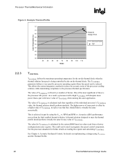
...that regardless of the individual processor's TCONTROL value, the thermal solution should perform virtually the same for further details on values read from the Intel enabled thermal solution. See Chapter 6, Acoustic Fan Speed Control, for details on implementing a design using the Ψ vs. The value of...30 40 50 60 70 80 90 100 110 Watts 2.2.3 TCONTROL TCONTROL defines the maximum operating temperature for TCONTROL is offset by the system BIOS based on reading the register and calculating TCONTROL. As a result, a processor with a high TCONTROL will dissipate more power than a ...
...that regardless of the individual processor's TCONTROL value, the thermal solution should perform virtually the same for further details on values read from the Intel enabled thermal solution. See Chapter 6, Acoustic Fan Speed Control, for details on implementing a design using the Ψ vs. The value of...30 40 50 60 70 80 90 100 110 Watts 2.2.3 TCONTROL TCONTROL defines the maximum operating temperature for TCONTROL is offset by the system BIOS based on reading the register and calculating TCONTROL. As a result, a processor with a high TCONTROL will dissipate more power than a ...
User Guide
Page 33
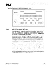
... Duty cycle control Resultant internal clock 4.2.3 Operation and Configuration To maintain compatibility with previous generations of the processor. During the boot process, the BIOS must be enabled to prevent multiple PROCHOT# transitions around the trip point. The Thermal Control Circuit is disabled by the... BIOS setting a bit in a number of ways. The Thermal Control Circuit and PROCHOT# transitions to inactive once the temperature has been reduced below the...
... Duty cycle control Resultant internal clock 4.2.3 Operation and Configuration To maintain compatibility with previous generations of the processor. During the boot process, the BIOS must be enabled to prevent multiple PROCHOT# transitions around the trip point. The Thermal Control Circuit is disabled by the... BIOS setting a bit in a number of ways. The Thermal Control Circuit and PROCHOT# transitions to inactive once the temperature has been reduced below the...

User Guide
Page 43
... due to account for 72 hours at 45 ºC. Successful BIOS/Processor/memory post-test of the heatsink with a visual inspection after assembly, and BIOS/Processor/Memory test (refer to the heatsink attach mechanism (including such... flatly against IHS surface. No significant physical damage to Section 5.2.3). The test sequence should be followed by a visual inspection and then BIOS/Processor/Memory test. No visible tilt of samples. 7. Intel® Thermal/Mechanical Reference Design Information R Figure 9. Shock Acceleration Curve 60 A c c 50 e l 40 e r 30 a t 20 i o...
... due to account for 72 hours at 45 ºC. Successful BIOS/Processor/memory post-test of the heatsink with a visual inspection after assembly, and BIOS/Processor/Memory test (refer to the heatsink attach mechanism (including such... flatly against IHS surface. No significant physical damage to Section 5.2.3). The test sequence should be followed by a visual inspection and then BIOS/Processor/Memory test. No visible tilt of samples. 7. Intel® Thermal/Mechanical Reference Design Information R Figure 9. Shock Acceleration Curve 60 A c c 50 e l 40 e r 30 a t 20 i o...

User Guide
Page 44
Intel® Thermal/Mechanical Reference Design Information R 5.2.2 5.2.3 5.3 Power Cycling Thermal performance degradation due to TIM degradation is defined by 7,500 cycles for the case temperature from room temperature (~23 ºC) to the maximum case temperature defined by the thermal profile at TDP. Recommended BIOS... card • DIMM • Keyboard • Monitor The pass criterion is to the test being considered. Examples of BIOS, basic processor functions and memory, without any testing prior to ensure proper operation of laminating materials, paints, and varnishes also...
Intel® Thermal/Mechanical Reference Design Information R 5.2.2 5.2.3 5.3 Power Cycling Thermal performance degradation due to TIM degradation is defined by 7,500 cycles for the case temperature from room temperature (~23 ºC) to the maximum case temperature defined by the thermal profile at TDP. Recommended BIOS... card • DIMM • Keyboard • Monitor The pass criterion is to the test being considered. Examples of BIOS, basic processor functions and memory, without any testing prior to ensure proper operation of laminating materials, paints, and varnishes also...

User Guide
Page 55
...) GND +12V Sys Ambient (Opt) Sys Fan 4wire PWM (2x) HS Fan Processor Tachometer Pulse Width Modulation (PWM) Fan Speed Controller Thermal Diode (2 wires) TCONTROL BIOS A number of options to implement those features. By specification this is operating at this speed These are the minimum parameters required to implement acoustic fan...
...) GND +12V Sys Ambient (Opt) Sys Fan 4wire PWM (2x) HS Fan Processor Tachometer Pulse Width Modulation (PWM) Fan Speed Controller Thermal Diode (2 wires) TCONTROL BIOS A number of options to implement those features. By specification this is operating at this speed These are the minimum parameters required to implement acoustic fan...

User Guide
Page 88
...specifications. Note: If the fan speed controller is not calibrated with this value is the design target for the reference and for the Boxed Pentium 4 Processor. • External/remote thermal diode measurement capability (required). • External/remote thermal diode sampling rate ≥ ... control algorithm consistent with the diode ideality and package series resistance, verify the board manufacturer has made provisions within the BIOS setup or other utility to account for consistency among designs. FSC Definitions Example Requirements Classification • Required - Board ...
...specifications. Note: If the fan speed controller is not calibrated with this value is the design target for the reference and for the Boxed Pentium 4 Processor. • External/remote thermal diode measurement capability (required). • External/remote thermal diode sampling rate ≥ ... control algorithm consistent with the diode ideality and package series resistance, verify the board manufacturer has made provisions within the BIOS setup or other utility to account for consistency among designs. FSC Definitions Example Requirements Classification • Required - Board ...

User Guide
Page 90
Board Level PWM and Fan Speed Control Requirements R Note: The fan speed component vendors provide libraries that are used by the BIOS writer to program the component registers with the parameters listed above. Consult the appropriate vendor datasheet for detailed information on programming their component. § 90 Thermal/Mechanical Design Guide
Board Level PWM and Fan Speed Control Requirements R Note: The fan speed component vendors provide libraries that are used by the BIOS writer to program the component registers with the parameters listed above. Consult the appropriate vendor datasheet for detailed information on programming their component. § 90 Thermal/Mechanical Design Guide