Product Guide
Page 5
Contents 1 Desktop Board Features Supported Operating Systems ...10 Desktop Board Components...11 Processor ...13 Main Memory ...14 Intel® Q963 Express Chipset...15 Intel Q963 Graphics Subsystem...15 Intel® Graphics Media Accelerator 3000 (Intel® GMA 3000) ...15 Onboard Audio Subsystem ...16 Input/Output ...# Signal Wake-up Support ...24 Speaker ...24 Battery ...24 Real-Time Clock ...24 2 Installing and Replacing Desktop Board Components Before You Begin...25 Installation Precautions...26 Prevent Power Supply Overload...26 Observe Safety and Regulatory Requirements ...26 ...
Contents 1 Desktop Board Features Supported Operating Systems ...10 Desktop Board Components...11 Processor ...13 Main Memory ...14 Intel® Q963 Express Chipset...15 Intel Q963 Graphics Subsystem...15 Intel® Graphics Media Accelerator 3000 (Intel® GMA 3000) ...15 Onboard Audio Subsystem ...16 Input/Output ...# Signal Wake-up Support ...24 Speaker ...24 Battery ...24 Real-Time Clock ...24 2 Installing and Replacing Desktop Board Components Before You Begin...25 Installation Precautions...26 Prevent Power Supply Overload...26 Observe Safety and Regulatory Requirements ...26 ...

Product Guide
Page 6
Intel Desktop Board DQ963FX Product Guide Installing and Removing a Processor...29 Installing a Processor ...29 Installing the Processor Fan Heat Sink...32 Connecting the Processor Fan Heat Sink Cable ...32 ... IDE Cable...38 Connecting the Serial ATA (SATA) Cable ...39 Connecting to Internal Headers...40 Connecting to the HD Audio Link Header ...41 Installing a Front Panel Audio Solution for Intel® High Definition Audio ...41 Connecting to the Serial Port Header...42 Connecting to the Alternate Front Panel Power LED Header...43 Connecting to...
Intel Desktop Board DQ963FX Product Guide Installing and Removing a Processor...29 Installing a Processor ...29 Installing the Processor Fan Heat Sink...32 Connecting the Processor Fan Heat Sink Cable ...32 ... IDE Cable...38 Connecting the Serial ATA (SATA) Cable ...39 Connecting to Internal Headers...40 Connecting to the HD Audio Link Header ...41 Installing a Front Panel Audio Solution for Intel® High Definition Audio ...41 Connecting to the Serial Port Header...42 Connecting to the Alternate Front Panel Power LED Header...43 Connecting to...

Product Guide
Page 7
...Block...48 Back Panel Connectors ...50 Removing the Battery ...55 vii Desktop Board DQ963FX Components ...11 LAN Connector LEDs ...17 Location of Standby Power Indicator ...23 Installing the I/O Shield ...27 Desktop Board DQ963FX Mounting Screw Hole Locations...28 Lift Socket Lever ...29 Lift the Load... Headers ...40 Back Panel Audio Connectors ...44 Location of Chassis Fan Headers ...45 Connecting Power Supply Cables ...46 Location of Other Connectors and Headers...47 Location of Conformity Statement ...64 Product Ecology Statements ...65 Lead-Free Desktop Board ...68 EMC Regulations ...69...
...Block...48 Back Panel Connectors ...50 Removing the Battery ...55 vii Desktop Board DQ963FX Components ...11 LAN Connector LEDs ...17 Location of Standby Power Indicator ...23 Installing the I/O Shield ...27 Desktop Board DQ963FX Mounting Screw Hole Locations...28 Lift Socket Lever ...29 Lift the Load... Headers ...40 Back Panel Audio Connectors ...44 Location of Chassis Fan Headers ...45 Connecting Power Supply Cables ...46 Location of Other Connectors and Headers...47 Location of Conformity Statement ...64 Product Ecology Statements ...65 Lead-Free Desktop Board ...68 EMC Regulations ...69...

Product Guide
Page 8
Feature Summary ...9 Desktop Board DQ963FX Components ...12 LAN Connector LEDs ...17 HD Audio Link Header Signal Names ...41 Front Panel Audio Header Signal Names for Intel High Definition Audio...41 AC '97 Audio Header Signal Names ...42 Serial Port Header Signal Names ...42 Alternate Front Panel Power ... Setup Program Modes ...48 Beep Codes...61 BIOS Error Messages ...61 Safety Regulations...63 Lead-Free Board Markings ...68 EMC Regulations...69 Product Certification Markings ...71 viii Intel Desktop Board DQ963FX Product Guide Tables 1. 2. 3. 4. 5. 6. 7. 8. 9. 10. 11. 12. 13. 14. 15. 16...
Feature Summary ...9 Desktop Board DQ963FX Components ...12 LAN Connector LEDs ...17 HD Audio Link Header Signal Names ...41 Front Panel Audio Header Signal Names for Intel High Definition Audio...41 AC '97 Audio Header Signal Names ...42 Serial Port Header Signal Names ...42 Alternate Front Panel Power ... Setup Program Modes ...48 Beep Codes...61 BIOS Error Messages ...61 Safety Regulations...63 Lead-Free Board Markings ...68 EMC Regulations...69 Product Certification Markings ...71 viii Intel Desktop Board DQ963FX Product Guide Tables 1. 2. 3. 4. 5. 6. 7. 8. 9. 10. 11. 12. 13. 14. 15. 16...

Product Guide
Page 9
... audio codec • HD Audio Link header Expansion Capabilities Peripheral Interfaces • Three PCI Express x1 connectors • Three PCI connectors • Up to 10 USB 2.0 ports ― Six ports routed to the back panel ― Four ports routed to 8 GB of system memory Chipset Intel® Q963 Express Chipset consisting of Intel® Desktop Board DQ963FX...
... audio codec • HD Audio Link header Expansion Capabilities Peripheral Interfaces • Three PCI Express x1 connectors • Three PCI connectors • Up to 10 USB 2.0 ports ― Six ports routed to the back panel ― Four ports routed to 8 GB of system memory Chipset Intel® Q963 Express Chipset consisting of Intel® Desktop Board DQ963FX...

Product Guide
Page 12
... USB 2.0 headers Speaker Related Links: Go to the following links for more information about Desktop Board DQ963FX Supported processors Audio software and utilities LAN software and drivers http://www.intel.com/design/motherbd http://support.intel.com/support/motherboards/desktop http://support.intel.com/support/motherboards/desktop http://www.intel.com/design/motherbd http://www.intel.com/design/motherbd 12 Intel Desktop Board DQ963FX Product Guide Table 2.
... USB 2.0 headers Speaker Related Links: Go to the following links for more information about Desktop Board DQ963FX Supported processors Audio software and utilities LAN software and drivers http://www.intel.com/design/motherbd http://support.intel.com/support/motherboards/desktop http://support.intel.com/support/motherboards/desktop http://www.intel.com/design/motherbd http://www.intel.com/design/motherbd 12 Intel Desktop Board DQ963FX Product Guide Table 2.

Product Guide
Page 16
...: Go to the following link or pages for more information about Audio drivers and utilities http://support.intel.com/support/motherboards/desktop/ Installing the front panel audio solution, page 41 The location of audio connectors, Figure 21 on page 44 • • Input/... that enables the audio codec to recognize the device that includes a SigmaTel STAC9227 audio codec and an HD Audio Link header. Intel Desktop Board DQ963FX Product Guide Onboard Audio Subsystem Desktop Board DQ963FX has a flexible 6-channel (5.1) onboard audio subsystem that is connected to an audio port and retask ...
...: Go to the following link or pages for more information about Audio drivers and utilities http://support.intel.com/support/motherboards/desktop/ Installing the front panel audio solution, page 41 The location of audio connectors, Figure 21 on page 44 • • Input/... that enables the audio codec to recognize the device that includes a SigmaTel STAC9227 audio codec and an HD Audio Link header. Intel Desktop Board DQ963FX Product Guide Onboard Audio Subsystem Desktop Board DQ963FX has a flexible 6-channel (5.1) onboard audio subsystem that is connected to an audio port and retask ...

Product Guide
Page 25
...desktop board Install and remove a processor Install and remove memory Connect the IDE and Serial ATA cables Connect to the internal headers Connect to record information about your computer, such as model, serial numbers, installed options, and configuration information. If such a station is off. Set up a log to the flexible audio...or perform any of the computer chassis. 25 Perform the procedures described in the correct order. Some circuitry on the board can damage components. Failure to operate even though the front panel power button is not available, you can result in...
...desktop board Install and remove a processor Install and remove memory Connect the IDE and Serial ATA cables Connect to the internal headers Connect to record information about your computer, such as model, serial numbers, installed options, and configuration information. If such a station is off. Set up a log to the flexible audio...or perform any of the computer chassis. 25 Perform the procedures described in the correct order. Some circuitry on the board can damage components. Failure to operate even though the front panel power button is not available, you can result in...

Product Guide
Page 40
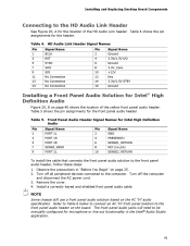
Intel Desktop Board DQ963FX Product Guide Connecting to Internal Headers Before connecting cables to the internal headers, observe the precautions in "Before You Begin" on page 25. Figure 20 shows the location of the internal headers. Item A B C D E F Description HD Audio Link Front panel audio Serial port Alternate front panel power LED Front panel USB 2.0 Figure 20. Internal Headers 40
Intel Desktop Board DQ963FX Product Guide Connecting to Internal Headers Before connecting cables to the internal headers, observe the precautions in "Before You Begin" on page 25. Figure 20 shows the location of the internal headers. Item A B C D E F Description HD Audio Link Front panel audio Serial port Alternate front panel power LED Front panel USB 2.0 Figure 20. Internal Headers 40
Product Guide
Page 41
... 3.3V_Core +12V Key 3.3V/1.5V STBY Ground Installing a Front Panel Audio Solution for Intel® High Definition Audio Figure 20, B on the board. Table 5. Installing and Replacing Desktop Board Components Connecting to the front panel audio header, follow these steps: 1. Front Panel Audio Header Signal Names for Intel High Definition Audio Pin 1 3 5 7 9 Signal Name PORT 1L PORT 1R PORT 2R...
... 3.3V_Core +12V Key 3.3V/1.5V STBY Ground Installing a Front Panel Audio Solution for Intel® High Definition Audio Figure 20, B on the board. Table 5. Installing and Replacing Desktop Board Components Connecting to the front panel audio header, follow these steps: 1. Front Panel Audio Header Signal Names for Intel High Definition Audio Pin 1 3 5 7 9 Signal Name PORT 1L PORT 1R PORT 2R...

Product Guide
Page 42
...# Ground RTS RI Pin 2 4 6 8 10 Signal Name RXD# DTR DSR CTS No Connection 42 To restore back panel audio, follow these steps: 1. Remove the front panel audio cable. 5. Table 7. Intel Desktop Board DQ963FX Product Guide Table 6. AC '97 Audio Header Signal Names Pin 1 3 5 7 9 Signal Name MIC MIC_BIAS FP_OUT_R AUD_5V FP_OUT_L Pin 2 4 6 8 10 Signal Name AUD_GND AUD_GND FP_RETURN_R...
...# Ground RTS RI Pin 2 4 6 8 10 Signal Name RXD# DTR DSR CTS No Connection 42 To restore back panel audio, follow these steps: 1. Remove the front panel audio cable. 5. Table 7. Intel Desktop Board DQ963FX Product Guide Table 6. AC '97 Audio Header Signal Names Pin 1 3 5 7 9 Signal Name MIC MIC_BIAS FP_OUT_R AUD_5V FP_OUT_L Pin 2 4 6 8 10 Signal Name AUD_GND AUD_GND FP_RETURN_R...
Product Guide
Page 44
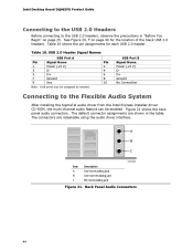
Intel Desktop Board DQ963FX Product Guide Connecting to the USB 2.0 Headers Before connecting to the Flexible Audio System After installing the SigmaTel audio driver from the Intel Express Installer driver CD-ROM, the multi-channel audio feature can be assigned as needed. The connectors are shown in the ... B Signal Name Power (+5 V) DD+ Ground No Connection Note: USB ports may be enabled. The default connector assignments are retaskable using the audio driver interface. Item A B C Description Line in/retasking jack Line out/retasking jack Mic in "Before You Begin" on page 40 for ...
Intel Desktop Board DQ963FX Product Guide Connecting to the USB 2.0 Headers Before connecting to the Flexible Audio System After installing the SigmaTel audio driver from the Intel Express Installer driver CD-ROM, the multi-channel audio feature can be assigned as needed. The connectors are shown in the ... B Signal Name Power (+5 V) DD+ Ground No Connection Note: USB ports may be enabled. The default connector assignments are retaskable using the audio driver interface. Item A B C Description Line in/retasking jack Line out/retasking jack Mic in "Before You Begin" on page 40 for ...

Product Guide
Page 50
Back Panel Connectors 50 Figure 26. Intel Desktop Board DQ963FX Product Guide Back Panel Connectors NOTE The line out connector, located on the back panel, is designed to this output. Figure 26 shows the back panel connectors. Poor audio quality may occur if passive (nonamplified) speakers are connected to power either headphones or amplified speakers only.
Back Panel Connectors 50 Figure 26. Intel Desktop Board DQ963FX Product Guide Back Panel Connectors NOTE The line out connector, located on the back panel, is designed to this output. Figure 26 shows the back panel connectors. Poor audio quality may occur if passive (nonamplified) speakers are connected to power either headphones or amplified speakers only.


