
Product Guide
Page 3
... components Updating the BIOS: instructions on how to important information. Intended Audience The Product Guide is not intended for technically qualified personnel. may not be supported without further evaluation by Intel. Use Only for Intel® Desktop Board DQ963FX. iii It is intended for general audiences. Preface This Product Guide gives information about board layout, component installation, BIOS update, and regulatory requirements for Intended Applications All Intel desktop boards are used...
... components Updating the BIOS: instructions on how to important information. Intended Audience The Product Guide is not intended for technically qualified personnel. may not be supported without further evaluation by Intel. Use Only for Intel® Desktop Board DQ963FX. iii It is intended for general audiences. Preface This Product Guide gives information about board layout, component installation, BIOS update, and regulatory requirements for Intended Applications All Intel desktop boards are used...
Product Guide
Page 5
... ...19 PCI and PCI Express* Auto Configuration ...19 Security Passwords ...19 Hardware Management Features ...20 Hardware Monitoring and Fan Speed Control ...20 Chassis Intrusion ...20 Power Management Features ...21 ACPI ...21 Power Connectors ...21 Fan Headers ...21 LAN Wake Capabilities...22 Instantly Available PC Technology...22 +5 V Standby Power Indicator LED ...23 Wake from USB ...23 Wake from PS/2 Keyboard/Mouse...23 PME# Signal Wake-up Support ...24 WAKE# Signal Wake-up Support ...24 Speaker ...24 Battery ...24 Real-Time Clock ...24 2 Installing and Replacing Desktop Board Components...
... ...19 PCI and PCI Express* Auto Configuration ...19 Security Passwords ...19 Hardware Management Features ...20 Hardware Monitoring and Fan Speed Control ...20 Chassis Intrusion ...20 Power Management Features ...21 ACPI ...21 Power Connectors ...21 Fan Headers ...21 LAN Wake Capabilities...22 Instantly Available PC Technology...22 +5 V Standby Power Indicator LED ...23 Wake from USB ...23 Wake from PS/2 Keyboard/Mouse...23 PME# Signal Wake-up Support ...24 WAKE# Signal Wake-up Support ...24 Speaker ...24 Battery ...24 Real-Time Clock ...24 2 Installing and Replacing Desktop Board Components...

Product Guide
Page 6
... Chassis Fan Cables...45 Connecting Power Cables...46 Other Connectors and Headers ...47 Setting the BIOS Configuration Jumper ...48 Clearing Passwords...49 Back Panel Connectors...50 3 Updating the BIOS Updating the BIOS with the Intel® Express BIOS Update Utility ...57 Updating the BIOS with the ISO Image BIOS Update File or the Iflash Memory Update Utility ...58 Obtaining the BIOS Update File ...58 Updating the BIOS with the ISO Image BIOS Update File...58 Updating the BIOS with Iflash ...59 Recovering the BIOS ...60 A Error Messages and Indicators BIOS Beep Codes ...61 BIOS Error...
... Chassis Fan Cables...45 Connecting Power Cables...46 Other Connectors and Headers ...47 Setting the BIOS Configuration Jumper ...48 Clearing Passwords...49 Back Panel Connectors...50 3 Updating the BIOS Updating the BIOS with the Intel® Express BIOS Update Utility ...57 Updating the BIOS with the ISO Image BIOS Update File or the Iflash Memory Update Utility ...58 Obtaining the BIOS Update File ...58 Updating the BIOS with the ISO Image BIOS Update File...58 Updating the BIOS with Iflash ...59 Recovering the BIOS ...60 A Error Messages and Indicators BIOS Beep Codes ...61 BIOS Error...

Product Guide
Page 7
... Dual Channel Memory Configuration Example 1...33 Dual Channel Memory Configuration Example 2...34 Dual Channel Memory Configuration Example 3...34 Use DDR2 DIMMs ...35 Installing a DIMM ...36 Connecting the IDE Cable ...38 Connecting the Serial ATA Cable...39 Internal Headers ...40 Back Panel Audio Connectors ...44 Location of Chassis Fan Headers ...45 Connecting Power Supply Cables ...46 Location of Other Connectors and Headers...47 Location of Conformity Statement ...64 Product Ecology Statements ...65 Lead-Free Desktop Board ...68 EMC Regulations ...69 Ensure Electromagnetic Compatibility...
... Dual Channel Memory Configuration Example 1...33 Dual Channel Memory Configuration Example 2...34 Dual Channel Memory Configuration Example 3...34 Use DDR2 DIMMs ...35 Installing a DIMM ...36 Connecting the IDE Cable ...38 Connecting the Serial ATA Cable...39 Internal Headers ...40 Back Panel Audio Connectors ...44 Location of Chassis Fan Headers ...45 Connecting Power Supply Cables ...46 Location of Other Connectors and Headers...47 Location of Conformity Statement ...64 Product Ecology Statements ...65 Lead-Free Desktop Board ...68 EMC Regulations ...69 Ensure Electromagnetic Compatibility...

Product Guide
Page 8
.... 16. 17. Feature Summary ...9 Desktop Board DQ963FX Components ...12 LAN Connector LEDs ...17 HD Audio Link Header Signal Names ...41 Front Panel Audio Header Signal Names for Intel High Definition Audio...41 AC '97 Audio Header Signal Names ...42 Serial Port Header Signal Names ...42 Alternate Front Panel Power LED Header...43 Front Panel Header ...43 USB 2.0 Header Signal Names...44 Jumper Settings for the BIOS Setup Program Modes ...48 Beep Codes...61 BIOS Error Messages ...61 Safety Regulations...63 Lead-Free Board Markings ...68 EMC Regulations...69...
.... 16. 17. Feature Summary ...9 Desktop Board DQ963FX Components ...12 LAN Connector LEDs ...17 HD Audio Link Header Signal Names ...41 Front Panel Audio Header Signal Names for Intel High Definition Audio...41 AC '97 Audio Header Signal Names ...42 Serial Port Header Signal Names ...42 Alternate Front Panel Power LED Header...43 Front Panel Header ...43 USB 2.0 Header Signal Names...44 Jumper Settings for the BIOS Setup Program Modes ...48 Beep Codes...61 BIOS Error Messages ...61 Safety Regulations...63 Lead-Free Board Markings ...68 EMC Regulations...69...

Product Guide
Page 9
...; Three PCI Express x1 connectors • Three PCI connectors • Up to 10 USB 2.0 ports ― Six ports routed to the back panel ― Four ports routed to 8 GB of system memory Chipset Intel® Q963 Express Chipset consisting of the desktop board. Table 1 summarizes the major features of : • Intel® Q963 Express Chipset Graphics Memory Controller Hub (GMCH) • Intel® 82801HB I/O Controller Hub (ICH8) Graphics Audio Intel® Q963 Express Chipset with ATA-66/100 support (two devices) •...
...; Three PCI Express x1 connectors • Three PCI connectors • Up to 10 USB 2.0 ports ― Six ports routed to the back panel ― Four ports routed to 8 GB of system memory Chipset Intel® Q963 Express Chipset consisting of the desktop board. Table 1 summarizes the major features of : • Intel® Q963 Express Chipset Graphics Memory Controller Hub (GMCH) • Intel® 82801HB I/O Controller Hub (ICH8) Graphics Audio Intel® Q963 Express Chipset with ATA-66/100 support (two devices) •...

Product Guide
Page 10
Intel Desktop Board DQ963FX Product Guide Table 1. Feature Summary (continued) BIOS • Intel® Platform Innovation Framework for extensible firmware interface • 8 Mbit symmetrical flash memory • Support for SMBIOS • Intel® Rapid BIOS Boot • Intel® Express BIOS Update Power Management • Support for Advanced Configuration and Power Interface (ACPI) • Suspend to RAM (STR) • Wake on USB, PCI Express, PS/2, LAN, and front panel Hardware Management Hardware monitor with: • Three fan sensing inputs used to monitor fan activity &#...
Intel Desktop Board DQ963FX Product Guide Table 1. Feature Summary (continued) BIOS • Intel® Platform Innovation Framework for extensible firmware interface • 8 Mbit symmetrical flash memory • Support for SMBIOS • Intel® Rapid BIOS Boot • Intel® Express BIOS Update Power Management • Support for Advanced Configuration and Power Interface (ACPI) • Suspend to RAM (STR) • Wake on USB, PCI Express, PS/2, LAN, and front panel Hardware Management Hardware monitor with: • Three fan sensing inputs used to monitor fan activity &#...

Product Guide
Page 12
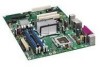
... Serial header Main power connector (2 x 12 pin) Diskette drive connector DDR2 DIMM 0 sockets DDR2 DIMM 1 sockets Battery Front chassis fan header (3-pin) Chassis intrusion header BIOS configuration jumper block Alternate front panel power LED header Front panel header Serial ATA connectors IDE connector High-speed USB 2.0 headers Speaker Related Links: Go to the following links for more information about Desktop Board DQ963FX Supported processors Audio software and utilities LAN software and drivers http://www.intel.com/design/motherbd http://support.intel.com/support/motherboards/desktop...
... Serial header Main power connector (2 x 12 pin) Diskette drive connector DDR2 DIMM 0 sockets DDR2 DIMM 1 sockets Battery Front chassis fan header (3-pin) Chassis intrusion header BIOS configuration jumper block Alternate front panel power LED header Front panel header Serial ATA connectors IDE connector High-speed USB 2.0 headers Speaker Related Links: Go to the following links for more information about Desktop Board DQ963FX Supported processors Audio software and utilities LAN software and drivers http://www.intel.com/design/motherbd http://support.intel.com/support/motherboards/desktop...

Product Guide
Page 14
... 4-4-4 only ― Serial Presence Detect (SPD) memory only ― Memory configurations listed below . • • Four 240-pin Double Data Rate 2 (DDR2) SDRAM Dual Inline Memory Module (DIMM) connectors with DIMMs that support the Serial Presence Detect (SPD) data structure. If your memory modules do not support SPD, you will attempt to the following links or pages for normal operation. Intel Desktop Board DQ963FX Product Guide Main Memory NOTE To...
... 4-4-4 only ― Serial Presence Detect (SPD) memory only ― Memory configurations listed below . • • Four 240-pin Double Data Rate 2 (DDR2) SDRAM Dual Inline Memory Module (DIMM) connectors with DIMMs that support the Serial Presence Detect (SPD) data structure. If your memory modules do not support SPD, you will attempt to the following links or pages for normal operation. Intel Desktop Board DQ963FX Product Guide Main Memory NOTE To...

Product Guide
Page 16
...; Microphone in /retasking jack Related Links: Go to an audio port and retask the connector via the audio driver. Intel Desktop Board DQ963FX Product Guide Onboard Audio Subsystem Desktop Board DQ963FX has a flexible 6-channel (5.1) onboard audio subsystem that is connected to the following link or pages for more information about Audio drivers and utilities http://support.intel.com/support/motherboards/desktop/ Installing the front panel audio solution, page 41 The location of the audio devices: ― Line in/retasking jack ― Line out...
...; Microphone in /retasking jack Related Links: Go to an audio port and retask the connector via the audio driver. Intel Desktop Board DQ963FX Product Guide Onboard Audio Subsystem Desktop Board DQ963FX has a flexible 6-channel (5.1) onboard audio subsystem that is connected to the following link or pages for more information about Audio drivers and utilities http://support.intel.com/support/motherboards/desktop/ Installing the front panel audio solution, page 41 The location of the audio devices: ― Line in/retasking jack ― Line out...
Product Guide
Page 18
... do not support USB 2.0. Disabling Hi-Speed USB in the BIOS reverts all USB 2.0 ports to 10 USB 2.0 ports via ICH8, connecting one device per channel. USB 2.0 ports are backward compatible with USB 1.1 devices. Use a shielded cable that have an unshielded cable attached to a USB port might not meet FCC Class B requirements, even if no device or a low-speed USB device is attached to two IDE devices (such as hard drives) ATAPI-style devices (such as hard disk drives and CD-ROM drives. Intel Desktop Board DQ963FX Product Guide Hi-Speed USB 2.0 Support NOTE Computer...
... do not support USB 2.0. Disabling Hi-Speed USB in the BIOS reverts all USB 2.0 ports to 10 USB 2.0 ports via ICH8, connecting one device per channel. USB 2.0 ports are backward compatible with USB 1.1 devices. Use a shielded cable that have an unshielded cable attached to a USB port might not meet FCC Class B requirements, even if no device or a low-speed USB device is attached to two IDE devices (such as hard drives) ATAPI-style devices (such as hard disk drives and CD-ROM drives. Intel Desktop Board DQ963FX Product Guide Hi-Speed USB 2.0 Support NOTE Computer...

Product Guide
Page 19
... the following the instructions on page 57 in card. You do not need to Setup. You can boot the computer. PCI and PCI Express* Auto Configuration If you install a Serial ATA or IDE device (such as a hard drive) in your computer. Desktop Board Features BIOS The BIOS provides the Power-On Self-Test (POST), the BIOS Setup program, the PCI/PCI Express and IDE auto-configuration utilities, and the video BIOS. Security Passwords The BIOS includes security features that add-in the BIOS Setup program. If...
... the following the instructions on page 57 in card. You do not need to Setup. You can boot the computer. PCI and PCI Express* Auto Configuration If you install a Serial ATA or IDE device (such as a hard drive) in your computer. Desktop Board Features BIOS The BIOS provides the Power-On Self-Test (POST), the BIOS Setup program, the PCI/PCI Express and IDE auto-configuration utilities, and the video BIOS. Security Passwords The BIOS includes security features that add-in the BIOS Setup program. If...

Product Guide
Page 20
... Channel A, DIMM 0 socket to enable Intel® Quiet System Technology Fan speed controllers and sensors integrated into the ICH8 Thermal sensors in the processor, GMCH, and ICH8 plus an onboard remote sensor Thermally monitored closed-loop fan control, for all onboard fans, that can adjust fan speed or switch the fans off as needed Chassis Intrusion The board supports a chassis security feature that can be connected to be compatible with the Wired for the location of Desktop Board DQ963FX enable the board...
... Channel A, DIMM 0 socket to enable Intel® Quiet System Technology Fan speed controllers and sensors integrated into the ICH8 Thermal sensors in the processor, GMCH, and ICH8 plus an onboard remote sensor Thermally monitored closed-loop fan control, for all onboard fans, that can adjust fan speed or switch the fans off as needed Chassis Intrusion The board supports a chassis security feature that can be connected to be compatible with the Wired for the location of Desktop Board DQ963FX enable the board...
Product Guide
Page 21
...23 on or off the computer power through the Advanced Configuration and Power Interface (ACPI) Hardware support: ― Power connectors ― Fan headers ― LAN wake capabilities ― Instantly Available PC technology (Suspend to a tachometer input of the hardware monitoring and control device All fan headers support closed-loop fan control that provides full ACPI support. The desktop board has a 4-pin processor fan header, and a 4-pin and two 3-pin chassis fan headers. 21 Desktop Board Features Power Management Features Power management is implemented at several levels...
...23 on or off the computer power through the Advanced Configuration and Power Interface (ACPI) Hardware support: ― Power connectors ― Fan headers ― LAN wake capabilities ― Instantly Available PC technology (Suspend to a tachometer input of the hardware monitoring and control device All fan headers support closed-loop fan control that provides full ACPI support. The desktop board has a 4-pin processor fan header, and a 4-pin and two 3-pin chassis fan headers. 21 Desktop Board Features Power Management Features Power management is implemented at several levels...
Product Guide
Page 22
... effect ACPI S3 sleep state functionality. When signaled by the LED turning amber. Instantly Available PC technology enables the board to support multiple wake events from the PCI and/or USB buses exceeds power supply capacity, the desktop board may lose register settings stored in memory. If the computer has a dual-colored power LED on the front panel, the sleep state is indicated by a wake-up of delivering adequate +5 V standby current. Intel Desktop Board DQ963FX Product Guide LAN Wake Capabilities...
... effect ACPI S3 sleep state functionality. When signaled by the LED turning amber. Instantly Available PC technology enables the board to support multiple wake events from the PCI and/or USB buses exceeds power supply capacity, the desktop board may lose register settings stored in memory. If the computer has a dual-colored power LED on the front panel, the sleep state is indicated by a wake-up of delivering adequate +5 V standby current. Intel Desktop Board DQ963FX Product Guide LAN Wake Capabilities...
Product Guide
Page 33
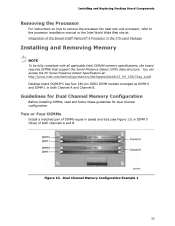
.../technology/memory/ddr/specs/dda18c32_64_128x72ag_a.pdf Desktop board DQ963FX has four 240-pin DDR2 DIMM sockets arranged as DIMM 0 and DIMM 1 in the 775-Land Package 1 Installing and Removing Memory NOTE To be fully compliant with all applicable Intel SDRAM memory specifications, the board requires DIMMs that support the Serial Presence Detect (SPD) data structure. You can access the PC Serial Presence Detect Specification at : Integration of both Channel A and Channel B. Figure 13. Dual Channel Memory Configuration...
.../technology/memory/ddr/specs/dda18c32_64_128x72ag_a.pdf Desktop board DQ963FX has four 240-pin DDR2 DIMM sockets arranged as DIMM 0 and DIMM 1 in the 775-Land Package 1 Installing and Removing Memory NOTE To be fully compliant with all applicable Intel SDRAM memory specifications, the board requires DIMMs that support the Serial Presence Detect (SPD) data structure. You can access the PC Serial Presence Detect Specification at : Integration of both Channel A and Channel B. Figure 13. Dual Channel Memory Configuration...
Product Guide
Page 44
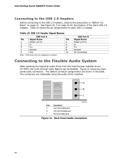
... the pin assignments for the location of the black USB 2.0 headers. USB 2.0 Header Signal Names USB Port A Pin 1 3 5 7 9 Signal Name Power (+5 V) DD+ Ground Key Pin 2 4 6 8 10 USB Port B Signal Name Power (+5 V) DD+ Ground No Connection Note: USB ports may be enabled. Intel Desktop Board DQ963FX Product Guide Connecting to the USB 2.0 Headers Before connecting to the Flexible Audio System After installing the SigmaTel audio driver from the Intel Express Installer driver CD-ROM, the multi-channel audio feature can be assigned as needed. Connecting to the USB 2.0 headers, observe...
... the pin assignments for the location of the black USB 2.0 headers. USB 2.0 Header Signal Names USB Port A Pin 1 3 5 7 9 Signal Name Power (+5 V) DD+ Ground Key Pin 2 4 6 8 10 USB Port B Signal Name Power (+5 V) DD+ Ground No Connection Note: USB ports may be enabled. Intel Desktop Board DQ963FX Product Guide Connecting to the USB 2.0 Headers Before connecting to the Flexible Audio System After installing the SigmaTel audio driver from the Intel Express Installer driver CD-ROM, the multi-channel audio feature can be assigned as needed. Connecting to the USB 2.0 headers, observe...
Product Guide
Page 49
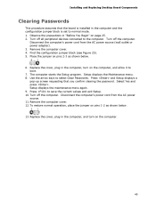
... the precautions in the computer, and turn on the computer. 49 Use the arrow keys to normal mode. 1. Setup displays the maintenance menu again. 9. Place the jumper on page 25. 2. Disconnect the computer's power cord from the AC power source. 11. Installing and Replacing Desktop Board Components Clearing Passwords This procedure assumes that you confirm clearing the password. Turn off all peripheral devices connected to save the current values and exit...
... the precautions in the computer, and turn on the computer. 49 Use the arrow keys to normal mode. 1. Setup displays the maintenance menu again. 9. Place the jumper on page 25. 2. Disconnect the computer's power cord from the AC power source. 11. Installing and Replacing Desktop Board Components Clearing Passwords This procedure assumes that you confirm clearing the password. Turn off all peripheral devices connected to save the current values and exit...

Product Guide
Page 57
... hard drive where it was saved. Follow the instructions provided in the Windows environment. Updating the BIOS with the Intel Express BIOS Update utility: 1. This is useful if you can also save this file to a removable USB device. This chapter tells you how to update the BIOS by pressing the key after the Power-On Self-Test (POST) memory test begins and before the operating system boot begins. This runs the update program. 6. To update...
... hard drive where it was saved. Follow the instructions provided in the Windows environment. Updating the BIOS with the Intel Express BIOS Update utility: 1. This is useful if you can also save this file to a removable USB device. This chapter tells you how to update the BIOS by pressing the key after the Power-On Self-Test (POST) memory test begins and before the operating system boot begins. This runs the update program. 6. To update...

Product Guide
Page 58
... Iflash BIOS Update utility file. The IFlash BIOS update file contains New BIOS file (including the Intel® Management Engine Firmware Image) Intel® Integrator Toolkit Configuration File (optional) Intel Flash Memory Update Utility You can be used to remove the BIOS configuration jumper. Updating the BIOS with the ISO Image BIOS Update File or the Iflash Memory Update Utility You can update to a new version of the BIOS by using either of these files files through your computer supplier or by navigating to the Desktop Board DQ963FX page on the computer's hard drive...
... Iflash BIOS Update utility file. The IFlash BIOS update file contains New BIOS file (including the Intel® Management Engine Firmware Image) Intel® Integrator Toolkit Configuration File (optional) Intel Flash Memory Update Utility You can be used to remove the BIOS configuration jumper. Updating the BIOS with the ISO Image BIOS Update File or the Iflash Memory Update Utility You can update to a new version of the BIOS by using either of these files files through your computer supplier or by navigating to the Desktop Board DQ963FX page on the computer's hard drive...


