Product Guide
Page 5
Contents 1 Desktop Board Features Supported Operating Systems ...10 Desktop Board Components...11 Processor ...13 Main Memory ...14 Intel® Q963 Express Chipset...15 Intel Q963 Graphics Subsystem...15 Intel® Graphics Media Accelerator 3000 (Intel® GMA 3000) ...15 Onboard Audio Subsystem ...16 Input/Output ...# Signal Wake-up Support ...24 Speaker ...24 Battery ...24 Real-Time Clock ...24 2 Installing and Replacing Desktop Board Components Before You Begin...25 Installation Precautions...26 Prevent Power Supply Overload...26 Observe Safety and Regulatory Requirements ...26 ...
Contents 1 Desktop Board Features Supported Operating Systems ...10 Desktop Board Components...11 Processor ...13 Main Memory ...14 Intel® Q963 Express Chipset...15 Intel Q963 Graphics Subsystem...15 Intel® Graphics Media Accelerator 3000 (Intel® GMA 3000) ...15 Onboard Audio Subsystem ...16 Input/Output ...# Signal Wake-up Support ...24 Speaker ...24 Battery ...24 Real-Time Clock ...24 2 Installing and Replacing Desktop Board Components Before You Begin...25 Installation Precautions...26 Prevent Power Supply Overload...26 Observe Safety and Regulatory Requirements ...26 ...

Product Guide
Page 6
Intel Desktop Board DQ963FX Product Guide Installing and Removing a Processor...29 Installing a Processor ...29 Installing the Processor Fan Heat Sink...32 Connecting the Processor Fan Heat Sink Cable ...32 Removing the Processor ...33 Installing and Removing Memory ...33 Guidelines for Dual Channel Memory Configuration ...33 Two or ...the BIOS Configuration Jumper ...48 Clearing Passwords...49 Back Panel Connectors...50 3 Updating the BIOS Updating the BIOS with the Intel® Express BIOS Update Utility ...57 Updating the BIOS with the ISO Image BIOS Update File or the Iflash Memory Update...
Intel Desktop Board DQ963FX Product Guide Installing and Removing a Processor...29 Installing a Processor ...29 Installing the Processor Fan Heat Sink...32 Connecting the Processor Fan Heat Sink Cable ...32 Removing the Processor ...33 Installing and Removing Memory ...33 Guidelines for Dual Channel Memory Configuration ...33 Two or ...the BIOS Configuration Jumper ...48 Clearing Passwords...49 Back Panel Connectors...50 3 Updating the BIOS Updating the BIOS with the Intel® Express BIOS Update Utility ...57 Updating the BIOS with the ISO Image BIOS Update File or the Iflash Memory Update...

Product Guide
Page 7
... Battery ...55 vii Desktop Board DQ963FX Components ...11 LAN Connector LEDs ...17 Location of Standby Power Indicator ...23 Installing the I/O Shield ...27 Desktop Board DQ963FX Mounting Screw Hole Locations...28 Lift Socket Lever ...29 Lift the Load Plate...29 Remove the Protective Socket Cover ...30 Remove the Processor from the Protective Processor Cover ...30 Install Processor ...31 Close the...
... Battery ...55 vii Desktop Board DQ963FX Components ...11 LAN Connector LEDs ...17 Location of Standby Power Indicator ...23 Installing the I/O Shield ...27 Desktop Board DQ963FX Mounting Screw Hole Locations...28 Lift Socket Lever ...29 Lift the Load Plate...29 Remove the Protective Socket Cover ...30 Remove the Processor from the Protective Processor Cover ...30 Install Processor ...31 Close the...

Product Guide
Page 9
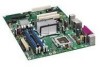
... Memory ATX (320.04 millimeters [11.60 inches] x 243.84 millimeters [9.60 inches]) Support for an Intel® processor in the LGA775 package • Four 240-pin, DDR2 1.8 V (only) SDRAM Dual Inline Memory Module (DIMM) sockets • 667/533 MHz single or dual channel ... connectors • Up to 10 USB 2.0 ports ― Six ports routed to the back panel ― Four ports routed to 8 GB of system memory Chipset Intel® Q963 Express Chipset consisting of Intel® Desktop Board DQ963FX. Table 1. Table 1 summarizes the major features of the...
... Memory ATX (320.04 millimeters [11.60 inches] x 243.84 millimeters [9.60 inches]) Support for an Intel® processor in the LGA775 package • Four 240-pin, DDR2 1.8 V (only) SDRAM Dual Inline Memory Module (DIMM) sockets • 667/533 MHz single or dual channel ... connectors • Up to 10 USB 2.0 ports ― Six ports routed to the back panel ― Four ports routed to 8 GB of system memory Chipset Intel® Q963 Express Chipset consisting of Intel® Desktop Board DQ963FX. Table 1. Table 1 summarizes the major features of the...

Product Guide
Page 12
... USB 2.0 headers Speaker Related Links: Go to the following links for more information about Desktop Board DQ963FX Supported processors Audio software and utilities LAN software and drivers http://www.intel.com/design/motherbd http://support.intel.com/support/motherboards/desktop http://support.intel.com/support/motherboards/desktop http://www.intel.com/design/motherbd http://www.intel.com/design/motherbd 12 Intel Desktop Board DQ963FX Product Guide Table 2.
... USB 2.0 headers Speaker Related Links: Go to the following links for more information about Desktop Board DQ963FX Supported processors Audio software and utilities LAN software and drivers http://www.intel.com/design/motherbd http://support.intel.com/support/motherboards/desktop http://support.intel.com/support/motherboards/desktop http://www.intel.com/design/motherbd http://www.intel.com/design/motherbd 12 Intel Desktop Board DQ963FX Product Guide Table 2.

Product Guide
Page 13
The supported processors list for Desktop Board DQ963FX is located on the web at: http://support.intel.com/support/motherboards/desktop/ Related Links: Go to the following page for more information about: Instructions on installing or upgrading the processor, page 29 in damage to the board, or the system may result in Chapter 2 13 Desktop Board Features Processor CAUTION Failure to use the...
The supported processors list for Desktop Board DQ963FX is located on the web at: http://support.intel.com/support/motherboards/desktop/ Related Links: Go to the following page for more information about: Instructions on installing or upgrading the processor, page 29 in damage to the board, or the system may result in Chapter 2 13 Desktop Board Features Processor CAUTION Failure to use the...
Product Guide
Page 18
...processor and peripheral devices such as CD-ROM drives) Older PIO Mode devices Ultra DMA-33 and ATA-66/100 protocols Serial ATA The desktop board supports four Serial ATA channels (3.0 Gb/s) via ICH8 (six ports routed to the back panel and four ports routed to USB 1.1 operation. Intel Desktop Board DQ963FX... for a full-speed USB device. USB 1.1 devices will function normally at USB 1.1 speeds. Expandability For system expansion, the desktop board provides the following: • • Three PCI Express x1 connectors Three PCI bus connectors 18 USB 2.0 ports are backward compatible...
...processor and peripheral devices such as CD-ROM drives) Older PIO Mode devices Ultra DMA-33 and ATA-66/100 protocols Serial ATA The desktop board supports four Serial ATA channels (3.0 Gb/s) via ICH8 (six ports routed to the back panel and four ports routed to USB 1.1 operation. Intel Desktop Board DQ963FX... for a full-speed USB device. USB 1.1 devices will function normally at USB 1.1 speeds. Expandability For system expansion, the desktop board provides the following: • • Three PCI Express x1 connectors Three PCI bus connectors 18 USB 2.0 ports are backward compatible...

Product Guide
Page 20
...on the chassis that detects if the chassis cover has been removed. Intel Desktop Board DQ963FX Product Guide Hardware Management Features The hardware management features of the chassis intrusion header. 20 The board has several hardware management features including the following Fan speed monitoring and control...Memory must be installed in the Channel A, DIMM 0 socket to enable Intel® Quiet System Technology Fan speed controllers and sensors integrated into the ICH8 Thermal sensors in the processor, GMCH, and ICH8 plus an onboard remote sensor Thermally monitored closed-loop ...
...on the chassis that detects if the chassis cover has been removed. Intel Desktop Board DQ963FX Product Guide Hardware Management Features The hardware management features of the chassis intrusion header. 20 The board has several hardware management features including the following Fan speed monitoring and control...Memory must be installed in the Channel A, DIMM 0 socket to enable Intel® Quiet System Technology Fan speed controllers and sensors integrated into the ICH8 Thermal sensors in the processor, GMCH, and ICH8 plus an onboard remote sensor Thermally monitored closed-loop ...
Product Guide
Page 21
... can be set by using the Last Power State feature in before power was interrupted (either on or off ). The use of the power connectors. Desktop Board Features Power Management Features Power management is in the ACPI S0 state. When resuming from PS/2 keyboard/mouse ― Power Management Event signal (PME#) wakeup... returns to a tachometer input of the hardware monitoring and control device All fan headers support closed-loop fan control that provides full ACPI support. The desktop board has a 4-pin processor fan header, and a 4-pin and two 3-pin chassis fan headers. 21
... can be set by using the Last Power State feature in before power was interrupted (either on or off ). The use of the power connectors. Desktop Board Features Power Management Features Power management is in the ACPI S0 state. When resuming from PS/2 keyboard/mouse ― Power Management Event signal (PME#) wakeup... returns to a tachometer input of the hardware monitoring and control device All fan headers support closed-loop fan control that provides full ACPI support. The desktop board has a 4-pin processor fan header, and a 4-pin and two 3-pin chassis fan headers. 21

Product Guide
Page 25
...follow the steps in each procedure in the correct order. 2 Installing and Replacing Desktop Board Components This chapter tells you how to Install the I/O shield Install and remove the desktop board Install and remove a processor Install and remove memory Connect the IDE and Serial ATA cables Connect to the...panel power button is not available, you open the computer or perform any of the computer chassis. 25 Some circuitry on the board can continue to disconnect power, telecommunications links, networks, or modems before you can provide some ESD protection by wearing an antistatic ...
...follow the steps in each procedure in the correct order. 2 Installing and Replacing Desktop Board Components This chapter tells you how to Install the I/O shield Install and remove the desktop board Install and remove a processor Install and remove memory Connect the IDE and Serial ATA cables Connect to the...panel power button is not available, you open the computer or perform any of the computer chassis. 25 Some circuitry on the board can continue to disconnect power, telecommunications links, networks, or modems before you can provide some ESD protection by wearing an antistatic ...
Product Guide
Page 26
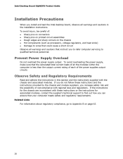
...instructions or the instructions for associated modules, contact the supplier's technical support to Appendix B on the chassis Hot components (such as processors, voltage regulators, and heat sinks) Damage to wires that could cause a short circuit Observe all warnings and cautions that the ...connectors Sharp pins on printed circuit assemblies Rough edges and sharp corners on page 63. 26 Intel Desktop Board DQ963FX Product Guide Installation Precautions When you install and test the Intel desktop board, observe all the modules within the computer is less than the output current rating of ...
...instructions or the instructions for associated modules, contact the supplier's technical support to Appendix B on the chassis Hot components (such as processors, voltage regulators, and heat sinks) Damage to wires that could cause a short circuit Observe all warnings and cautions that the ...connectors Sharp pins on printed circuit assemblies Rough edges and sharp corners on page 63. 26 Intel Desktop Board DQ963FX Product Guide Installation Precautions When you install and test the Intel desktop board, observe all the modules within the computer is less than the output current rating of ...
Product Guide
Page 29
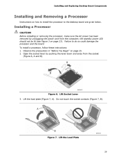
... the socket (Figure 6, A and B). Lift the load plate (Figure 7, A). Installing and Replacing Desktop Board Components Installing and Removing a Processor Instructions on how to install the processor to do so could damage the processor and the board. Installing a Processor CAUTION Before installing or removing the processor, make sure the AC power has been removed by pushing the lever down...
... the socket (Figure 6, A and B). Lift the load plate (Figure 7, A). Installing and Replacing Desktop Board Components Installing and Removing a Processor Instructions on how to install the processor to do so could damage the processor and the board. Installing a Processor CAUTION Before installing or removing the processor, make sure the AC power has been removed by pushing the lever down...
Product Guide
Page 30
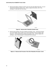
... edges, being careful not to touch the bottom of the processor (see Figure 9). Do not discard the protective processor cover. Always replace the processor cover if the processor is removed from the socket. Intel Desktop Board DQ963FX Product Guide 4. Figure 9. Remove the plastic protective socket cover from the Protective Processor Cover 30 Remove the Protective Socket Cover 5. Always replace...
... edges, being careful not to touch the bottom of the processor (see Figure 9). Do not discard the protective processor cover. Always replace the processor cover if the processor is removed from the socket. Intel Desktop Board DQ963FX Product Guide 4. Figure 9. Remove the plastic protective socket cover from the Protective Processor Cover 30 Remove the Protective Socket Cover 5. Always replace...

Product Guide
Page 31
Figure 10. Pressing down without tilting or sliding the processor in Figure 10. Figure 11. Installing and Replacing Desktop Board Components 6. Make sure fingers align to the socket cutouts (Figure 10, A). Align notches (Figure 10, B) with your thumb and index fingers oriented as shown in the socket. Install Processor 7. Close the Load Plate 31 Lower the processor straight down on the load plate (Figure 11, A) close and engage the socket lever (Figure 11, B). Hold the processor with the socket (Figure 10, C).
Figure 10. Pressing down without tilting or sliding the processor in Figure 10. Figure 11. Installing and Replacing Desktop Board Components 6. Make sure fingers align to the socket cutouts (Figure 10, A). Align notches (Figure 10, B) with your thumb and index fingers oriented as shown in the socket. Install Processor 7. Close the Load Plate 31 Lower the processor straight down on the load plate (Figure 11, A) close and engage the socket lever (Figure 11, B). Hold the processor with the socket (Figure 10, C).
Product Guide
Page 32
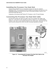
... the 3-pin fan cannot use the onboard fan control, the fan will always operate at : Integration of the Boxed Intel® Pentium® 4 Processor in Figure 12, A is recommended; Intel Desktop Board DQ963FX Product Guide Installing the Processor Fan Heat Sink Desktop Board DQ963FX has an integrated processor fan heat sink retention mechanism (RM). For instructions on how to attach the...
... the 3-pin fan cannot use the onboard fan control, the fan will always operate at : Integration of the Boxed Intel® Pentium® 4 Processor in Figure 12, A is recommended; Intel Desktop Board DQ963FX Product Guide Installing the Processor Fan Heat Sink Desktop Board DQ963FX has an integrated processor fan heat sink retention mechanism (RM). For instructions on how to attach the...
Product Guide
Page 33
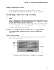
... Memory Configuration Example 1 33 Installing and Replacing Desktop Board Components Removing the Processor For instructions on how to remove the processor fan heat sink and processor, refer to the processor installation manual or the Intel World Wide Web site at : http://www.intel.com/technology/memory/ddr/specs/dda18c32_64_128x72ag_a.pdf Desktop board DQ963FX has four 240-pin DDR2 DIMM sockets arranged...
... Memory Configuration Example 1 33 Installing and Replacing Desktop Board Components Removing the Processor For instructions on how to remove the processor fan heat sink and processor, refer to the processor installation manual or the Intel World Wide Web site at : http://www.intel.com/technology/memory/ddr/specs/dda18c32_64_128x72ag_a.pdf Desktop board DQ963FX has four 240-pin DDR2 DIMM sockets arranged...
Product Guide
Page 46
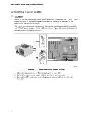
Connect the 12 V processor core voltage power supply cable to the 2 x 12 pin connector. 3. The 2 x 12 pin main power connector on page 25. 2. Observe the precautions in damage to the board or the system may not function properly. Intel Desktop Board DQ963FX Product Guide Connecting Power Cables CAUTION Failure to use the appropriate power supply and/or...
Connect the 12 V processor core voltage power supply cable to the 2 x 12 pin connector. 3. The 2 x 12 pin main power connector on page 25. 2. Observe the precautions in damage to the board or the system may not function properly. Intel Desktop Board DQ963FX Product Guide Connecting Power Cables CAUTION Failure to use the appropriate power supply and/or...

Product Guide
Page 61
A Error Messages and Indicators Desktop Board DQ963FX reports POST errors in Channel B. BIOS Error Messages Error Message PROCESSOR_THERMAL_TRIP_ERROR MULTI_BIT_ECC_ERROR SINGLE_BIT_ECC_ERROR CMOS_BATTERY_ERROR CMOS_CHECKSUM_ERROR CMOS_TIMER_ERROR MEMORY_SIZE_DECREASE_ERROR INTRUDER_DETECTION_ERROR SPD_TOLER_ERROR Explanation Processor was opened. The firmware has detected that ... occurred. DDR2 533 MHz memory assumed at slowest timings. Beep Codes Beep 3 Siren Description No memory Processor overheat (on the monitor BIOS Beep Codes The BIOS also issues a beep code (one long tone ...
A Error Messages and Indicators Desktop Board DQ963FX reports POST errors in Channel B. BIOS Error Messages Error Message PROCESSOR_THERMAL_TRIP_ERROR MULTI_BIT_ECC_ERROR SINGLE_BIT_ECC_ERROR CMOS_BATTERY_ERROR CMOS_CHECKSUM_ERROR CMOS_TIMER_ERROR MEMORY_SIZE_DECREASE_ERROR INTRUDER_DETECTION_ERROR SPD_TOLER_ERROR Explanation Processor was opened. The firmware has detected that ... occurred. DDR2 533 MHz memory assumed at slowest timings. Beep Codes Beep 3 Siren Description No memory Processor overheat (on the monitor BIOS Beep Codes The BIOS also issues a beep code (one long tone ...


