Product Guide
Page 6
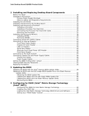
Intel Desktop Board DQ45EK Product Guide 2 Installing and Replacing Desktop Board Components Before You Begin 29 Installation Precautions 30 Prevent Power Supply Overload 30 Observe Safety and Regulatory Requirements 30 Installing the I/O Shield 31 Installing and Removing the Desktop Board 32 Installing and Removing a Processor 33 Installing a Processor 33 ...Jumper 50 Clearing BIOS Security Passwords 51 Replacing the Battery 52 3 Updating the BIOS Updating the BIOS with the Intel® Express BIOS Update Utility 59 Updating the BIOS with the ISO Image BIOS Update File or the Iflash ...
Intel Desktop Board DQ45EK Product Guide 2 Installing and Replacing Desktop Board Components Before You Begin 29 Installation Precautions 30 Prevent Power Supply Overload 30 Observe Safety and Regulatory Requirements 30 Installing the I/O Shield 31 Installing and Removing the Desktop Board 32 Installing and Removing a Processor 33 Installing a Processor 33 ...Jumper 50 Clearing BIOS Security Passwords 51 Replacing the Battery 52 3 Updating the BIOS Updating the BIOS with the Intel® Express BIOS Update Utility 59 Updating the BIOS with the ISO Image BIOS Update File or the Iflash ...
Product Guide
Page 7
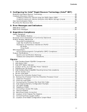
...Install the Processor 35 12. Location of the +5 V Standby Power Indicator 27 5. Intel Desktop Board DQ45EK Mounting Screw Hole Locations 32 7. Dual Channel Memory Configuration Example 38 15. Intel Desktop Board DQ45EK Components 11 2. Intel AMT Status Indicator 19 4. Lift the Load Plate 34 9. Remove the Protective Socket ...Headers 48 21. Connecting the Processor Fan Heat Sink Cable 37 14. Back Panel Audio Connectors 47 20. Installing the I/O Shield 31 6. Use DDR2 DIMMs 39 16. Connecting Power Supply Cables 49 22. Close the Load Plate 36 13. Installing ...
...Install the Processor 35 12. Location of the +5 V Standby Power Indicator 27 5. Intel Desktop Board DQ45EK Mounting Screw Hole Locations 32 7. Dual Channel Memory Configuration Example 38 15. Intel Desktop Board DQ45EK Components 11 2. Intel AMT Status Indicator 19 4. Lift the Load Plate 34 9. Remove the Protective Socket ...Headers 48 21. Connecting the Processor Fan Heat Sink Cable 37 14. Back Panel Audio Connectors 47 20. Installing the I/O Shield 31 6. Use DDR2 DIMMs 39 16. Connecting Power Supply Cables 49 22. Close the Load Plate 36 13. Installing ...
Product Guide
Page 21
... software, enhance the platform security capabilities. Desktop Board Features Intel® Trusted Execution Technology (Intel® TXT) Intel® Trusted Execution Technology (Intel® TXT) is a highly versatile set... of hardware extensions to address the increasing frequency and sophistication of software-based attacks. Additionally, thirdparty software may also be processed out of view of any other software. • Sealed storage shields...
... software, enhance the platform security capabilities. Desktop Board Features Intel® Trusted Execution Technology (Intel® TXT) Intel® Trusted Execution Technology (Intel® TXT) is a highly versatile set... of hardware extensions to address the increasing frequency and sophistication of software-based attacks. Additionally, thirdparty software may also be processed out of view of any other software. • Sealed storage shields...
Product Guide
Page 24
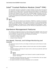
... battery (CR2032) to shield unencrypted keys and platform authentication information from softwarebased attacks. Hardware Management Features The hardware management features of the internal Intel TPM data. Please read the Intel TPM user guide and back-up Intel TPM keys and data before removing the battery. Intel Desktop Board DQ45EK Product Guide Intel® Trusted Platform Module (Intel® TPM) The...
... battery (CR2032) to shield unencrypted keys and platform authentication information from softwarebased attacks. Hardware Management Features The hardware management features of the internal Intel TPM data. Please read the Intel TPM user guide and back-up Intel TPM keys and data before removing the battery. Intel Desktop Board DQ45EK Product Guide Intel® Trusted Platform Module (Intel® TPM) The...

Product Guide
Page 29
..., networks, or modems before you open the computer or perform any of the computer chassis. 29 Some circuitry on the board can continue to operate even though the front panel power button is not available, you can provide some ESD protection by wearing an... discharge (ESD) can result in this chapter. If such a station is off. 2 Installing and Replacing Desktop Board Components This chapter tells you how to: • Install the I/O shield • Install and remove the Desktop Board • Install and remove a processor • Install and remove memory • Connect the Serial ATA ...
..., networks, or modems before you open the computer or perform any of the computer chassis. 29 Some circuitry on the board can continue to operate even though the front panel power button is not available, you can provide some ESD protection by wearing an... discharge (ESD) can result in this chapter. If such a station is off. 2 Installing and Replacing Desktop Board Components This chapter tells you how to: • Install the I/O shield • Install and remove the Desktop Board • Install and remove a processor • Install and remove memory • Connect the Serial ATA ...

Product Guide
Page 31
... components from the chassis supplier. Installing the I /O shield before installing the Desktop Board in the chassis. If the shield does not fit, obtain a properly sized shield from dust and foreign objects, and promotes correct airflow within the chassis. Install the I /O Shield 31 Installing and Replacing Desktop Board Components Installing the I/O Shield The Desktop Board comes with an I/O shield. When installed in Figure 5.
... components from the chassis supplier. Installing the I /O shield before installing the Desktop Board in the chassis. If the shield does not fit, obtain a properly sized shield from dust and foreign objects, and promotes correct airflow within the chassis. Install the I /O Shield 31 Installing and Replacing Desktop Board Components Installing the I/O Shield The Desktop Board comes with an I/O shield. When installed in Figure 5.

Product Guide
Page 45
...Signal Name Power (+5 V) DD+ Ground No Connection NOTE Computer systems that meets the requirements for each USB 2.0 header. Table 9. Use a shielded cable that have an unshielded cable attached to a USB port might not meet FCC Class B requirements, even if no device or a low-... Power (+5 V) 2 3 D- 4 5 D+ 6 7 Ground 8 9 Key 10 Note: USB ports may be used to the cable. Table 10. Installing and Replacing Desktop Board Components USB 2.0 Headers See Figure 18, C for the location of the two USB 2.0 headers. Table 10 shows the pin assignments for the header.
...Signal Name Power (+5 V) DD+ Ground No Connection NOTE Computer systems that meets the requirements for each USB 2.0 header. Table 9. Use a shielded cable that have an unshielded cable attached to a USB port might not meet FCC Class B requirements, even if no device or a low-... Power (+5 V) 2 3 D- 4 5 D+ 6 7 Ground 8 9 Key 10 Note: USB ports may be used to the cable. Table 10. Installing and Replacing Desktop Board Components USB 2.0 Headers See Figure 18, C for the location of the two USB 2.0 headers. Table 10 shows the pin assignments for the header.

Product Guide
Page 81
... following when reading the installation instructions for the host chassis, power supply, and other modules: • Product certifications or lack of certifications • External I/O cable shielding and filtering • Mounting, grounding, and bonding requirements • Keying connectors when mating the wrong connectors could be required on a representative sample of the newly...
... following when reading the installation instructions for the host chassis, power supply, and other modules: • Product certifications or lack of certifications • External I/O cable shielding and filtering • Mounting, grounding, and bonding requirements • Keying connectors when mating the wrong connectors could be required on a representative sample of the newly...