Product Guide
Page 6
Intel Desktop Board DP43TF Product Guide Installing and Removing a Processor 29 Installing a Processor 29 Installing a Processor Fan Heat Sink 32 Connecting the Processor Fan Heat Sink Cable 33 Removing ... Headers and Connectors 44 HD Audio Link Header 45 S/PDIF Connector 45 Chassis Intrusion Header 45 Front Panel HD Audio Header 46 USB 2.0 Headers 46 Serial Port Header 47 Front Panel Header 47 Alternate Front Panel Power LED Header 47 IEEE 1394a Header 48 Connecting to the Audio System 48 Connecting Chassis Fan...
Intel Desktop Board DP43TF Product Guide Installing and Removing a Processor 29 Installing a Processor 29 Installing a Processor Fan Heat Sink 32 Connecting the Processor Fan Heat Sink Cable 33 Removing ... Headers and Connectors 44 HD Audio Link Header 45 S/PDIF Connector 45 Chassis Intrusion Header 45 Front Panel HD Audio Header 46 USB 2.0 Headers 46 Serial Port Header 47 Front Panel Header 47 Alternate Front Panel Power LED Header 47 IEEE 1394a Header 48 Connecting to the Audio System 48 Connecting Chassis Fan...
Product Guide
Page 7
.... Connecting the IDE Cable 42 21. Connecting a Serial ATA Cable 43 22. Intel Desktop Board DP43TF Components 12 3. Intel Desktop Board DP43TF Mounting Screw Hole Locations 28 6. Connecting the Processor Fan Heat Sink Cable 33 13. Internal Headers and Connectors 44 23. Feature Summary 9 2. Front Panel Audio Header Signal Names 46 9. Location of Hazardous Substances (RoHS 71 EU RoHS...
.... Connecting the IDE Cable 42 21. Connecting a Serial ATA Cable 43 22. Intel Desktop Board DP43TF Components 12 3. Intel Desktop Board DP43TF Mounting Screw Hole Locations 28 6. Connecting the Processor Fan Heat Sink Cable 33 13. Internal Headers and Connectors 44 23. Feature Summary 9 2. Front Panel Audio Header Signal Names 46 9. Location of Hazardous Substances (RoHS 71 EU RoHS...
Product Guide
Page 8
Jumper Settings for the BIOS Setup Program Modes 52 15. Lead-Free Second Level Interconnect Marks 71 19. IEEE 1394a Header Signal Names 48 14. Beep Codes 63 16. Safety Standards 65 18. Alternate Front Panel Power LED Header Signal Names 47 13. BIOS Error Messages 63 17. Product Certification Markings 76 viii China RoHS Environmentally Friendly Use Period Mark 72 20. Front Panel Header Signal Names 47 12. Intel Desktop Board DP43TF Product Guide 11. EMC Regulations 74 21.
Jumper Settings for the BIOS Setup Program Modes 52 15. Lead-Free Second Level Interconnect Marks 71 19. IEEE 1394a Header Signal Names 48 14. Beep Codes 63 16. Safety Standards 65 18. Alternate Front Panel Power LED Header Signal Names 47 13. BIOS Error Messages 63 17. Product Certification Markings 76 viii China RoHS Environmentally Friendly Use Period Mark 72 20. Front Panel Header Signal Names 47 12. Intel Desktop Board DP43TF Product Guide 11. EMC Regulations 74 21.

Product Guide
Page 9
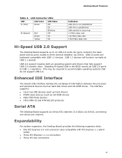
...three USB headers • Up to two IEEE 1394a ports: ― One port routed to the back panel ― One port routed to 8 GB of system memory Intel® P43 Express Chipset consisting of the Desktop Board. Feature Summary Form Factor Processor Main Memory Chipset Graphics Audio ATX (294.64 millimeters [11.60 inches... 1394a header • Six Serial ATA (SATA) channels (3.0 Gb/s) via ICH10 • One IDE interface with ATA-66/100 support (two devices) continued 9 Table 1. 1 Desktop Board Features This chapter briefly describes the features of Intel® Desktop Board DP43TF.
...three USB headers • Up to two IEEE 1394a ports: ― One port routed to the back panel ― One port routed to 8 GB of system memory Intel® P43 Express Chipset consisting of the Desktop Board. Feature Summary Form Factor Processor Main Memory Chipset Graphics Audio ATX (294.64 millimeters [11.60 inches... 1394a header • Six Serial ATA (SATA) channels (3.0 Gb/s) via ICH10 • One IDE interface with ATA-66/100 support (two devices) continued 9 Table 1. 1 Desktop Board Features This chapter briefly describes the features of Intel® Desktop Board DP43TF.
Product Guide
Page 10
...on USB, PCI, PCI Express, PS/2, LAN, and front panel • ENERGY STAR* capable Hardware Management Hardware monitor with: • Four fan sensing inputs used to monitor fan activity • Intel® Quiet System Technology (Intel® QST) fan speed control LAN Support • Voltage... • Microsoft Windows XP Professional x64 Edition • Microsoft Windows XP Home For more information about Intel Desktop Board DP43TF, including the Technical Product Specification (TPS), BIOS updates, and device drivers, go to http://support.intel.com/support/motherboards/desktop/. 10
...on USB, PCI, PCI Express, PS/2, LAN, and front panel • ENERGY STAR* capable Hardware Management Hardware monitor with: • Four fan sensing inputs used to monitor fan activity • Intel® Quiet System Technology (Intel® QST) fan speed control LAN Support • Voltage... • Microsoft Windows XP Professional x64 Edition • Microsoft Windows XP Home For more information about Intel Desktop Board DP43TF, including the Technical Product Specification (TPS), BIOS updates, and device drivers, go to http://support.intel.com/support/motherboards/desktop/. 10
Product Guide
Page 15
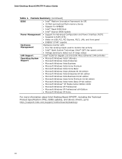
... with serialized IRQ support for the front panel and back panel audio jacks. Table 3. Desktop Board Features Audio Subsystem The onboard audio subsystem consists of the following: • Intel ICH10 I /O controller features the following locations for more information about: • Audio drivers and utilities http://support.intel.com/support/motherboards/desktop/ • Location of the onboard audio headers...
... with serialized IRQ support for the front panel and back panel audio jacks. Table 3. Desktop Board Features Audio Subsystem The onboard audio subsystem consists of the following: • Intel ICH10 I /O controller features the following locations for more information about: • Audio drivers and utilities http://support.intel.com/support/motherboards/desktop/ • Location of the onboard audio headers...
Product Guide
Page 16
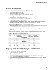
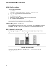
... Status LEDs Table 4 describes the LED states when the board is powered up and the LAN subsystem is operating. 16 Intel Desktop Board DP43TF Product Guide LAN Subsystem The LAN subsystem includes: • Intel® ICH10 • Intel 82567V Gigabit (10/100/1000 Mb/s) Ethernet LAN controller ... management For information about LAN software and drivers go to http://support.intel.com/support/motherboards/desktop LAN Subsystem Software For LAN software and drivers, refer to the Intel Desktop Board DP43TF link on the back panel (see Figure 2). LAN Status Indicators Two LEDs are built into the...
... Status LEDs Table 4 describes the LED states when the board is powered up and the LAN subsystem is operating. 16 Intel Desktop Board DP43TF Product Guide LAN Subsystem The LAN subsystem includes: • Intel® ICH10 • Intel 82567V Gigabit (10/100/1000 Mb/s) Ethernet LAN controller ... management For information about LAN software and drivers go to http://support.intel.com/support/motherboards/desktop LAN Subsystem Software For LAN software and drivers, refer to the Intel Desktop Board DP43TF link on the back panel (see Figure 2). LAN Status Indicators Two LEDs are built into the...
Product Guide
Page 17
.../s data rate 100 Mb/s data rate 1000 Mb/s data rate Hi-Speed USB 2.0 Support The Desktop Board supports up to 12 USB 2.0 ports (six ports routed to the back panel and six ports routed to accommodate operating systems that fully support USB 2.0 transfer rates. The interface supports...: • Up to USB 1.1 operation. Desktop Board Features Table 4. USB 2.0 support requires both an operating system and drivers...
.../s data rate 100 Mb/s data rate 1000 Mb/s data rate Hi-Speed USB 2.0 Support The Desktop Board supports up to 12 USB 2.0 ports (six ports routed to the back panel and six ports routed to accommodate operating systems that fully support USB 2.0 transfer rates. The interface supports...: • Up to USB 1.1 operation. Desktop Board Features Table 4. USB 2.0 support requires both an operating system and drivers...
Product Guide
Page 21
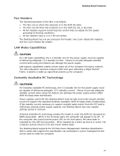
... CAUTIONS For Instantly Available PC technology, the 5 V standby line for the power supply must be capable of delivering adequate +5 V standby current. The Desktop Board has a 4-pin processor fan header, two 3-pin chassis fan headers, and one 4-pin chassis fan header. Failure to provide adequate standby current when ...when the computer is in the ACPI S0 state. • The fans are off . Desktop Board Features Fan Headers The function/operation of the fans is as follows: • The fans are on the front panel, the sleep state is in the ACPI S3, S4, or S5 state. • ...
... CAUTIONS For Instantly Available PC technology, the 5 V standby line for the power supply must be capable of delivering adequate +5 V standby current. The Desktop Board has a 4-pin processor fan header, two 3-pin chassis fan headers, and one 4-pin chassis fan header. Failure to provide adequate standby current when ...when the computer is in the ACPI S0 state. • The fans are off . Desktop Board Features Fan Headers The function/operation of the fans is as follows: • The fans are on the front panel, the sleep state is in the ACPI S3, S4, or S5 state. • ...
Product Guide
Page 25
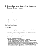
... links, networks, or modems before you how to: • Install the I/O shield • Install and remove the Desktop Board • Install and remove a processor • Install and remove memory • Install and remove a PCI Express x16...panel power button is not available, you begin: • Always follow the steps in each procedure in the correct order. • Set up a log to disconnect power, telecommunications links, networks, or modems before performing any procedures can damage components. If such a station is off. 2 Installing and Replacing Desktop Board...
... links, networks, or modems before you how to: • Install the I/O shield • Install and remove the Desktop Board • Install and remove a processor • Install and remove memory • Install and remove a PCI Express x16...panel power button is not available, you begin: • Always follow the steps in each procedure in the correct order. • Set up a log to disconnect power, telecommunications links, networks, or modems before performing any procedures can damage components. If such a station is off. 2 Installing and Replacing Desktop Board...

Product Guide
Page 39
Secure the card's metal bracket to the chassis back panel with a screw (Figure 18, B). Figure 18. Observe the precautions in the connector and the card retention notch on the card snaps into place around the retention mechanism pin on page 25. 2. Installing a PCI Express x16 Card 39 Place the card in the PCI Express x16 connector (Figure 18, A) and press down on the card until it is completely seated in "Before You Begin" on the connector. 3. Installing and Replacing Desktop Board Components Installing a PCI Express x16 Card 1.
Secure the card's metal bracket to the chassis back panel with a screw (Figure 18, B). Figure 18. Observe the precautions in the connector and the card retention notch on the card snaps into place around the retention mechanism pin on page 25. 2. Installing a PCI Express x16 Card 39 Place the card in the PCI Express x16 connector (Figure 18, A) and press down on the card until it is completely seated in "Before You Begin" on the connector. 3. Installing and Replacing Desktop Board Components Installing a PCI Express x16 Card 1.

Product Guide
Page 40
Observe the precautions in the notch. Remove the screw (Figure 19, A) that secures the card's metal bracket to remove the PCI Express x16 card from the connector (C). 4. This will release the card from the connector: 1. Removing a PCI Express x16 Card 40 Intel Desktop Board DP43TF Product Guide Removing the PCI Express x16 Card Follow these instructions to the chassis back panel. 3. Pull the card straight up. Figure 19. Push the card ejector lever down using the tip of a pencil or similar tool (Figure 19, B) in "Before You Begin" on page 25. 2.
Observe the precautions in the notch. Remove the screw (Figure 19, A) that secures the card's metal bracket to remove the PCI Express x16 card from the connector (C). 4. This will release the card from the connector: 1. Removing a PCI Express x16 Card 40 Intel Desktop Board DP43TF Product Guide Removing the PCI Express x16 Card Follow these instructions to the chassis back panel. 3. Pull the card straight up. Figure 19. Push the card ejector lever down using the tip of a pencil or similar tool (Figure 19, B) in "Before You Begin" on page 25. 2.

Product Guide
Page 44
Internal Headers and Connectors 44 Figure 22 shows the location of the internal headers and connectors. Intel Desktop Board DP43TF Product Guide Connecting to Internal Headers and Connectors Before connecting cables to the internal headers and connectors, observe the precautions in "Before You Begin" on page 25. Item Description A HD Audio Link B S/PDIF C Chassis intrusion D Audio E USB 2.0 (3) Item Description F Serial G Front panel H Alternate front panel power LED I IEEE 1394a Figure 22.
Internal Headers and Connectors 44 Figure 22 shows the location of the internal headers and connectors. Intel Desktop Board DP43TF Product Guide Connecting to Internal Headers and Connectors Before connecting cables to the internal headers and connectors, observe the precautions in "Before You Begin" on page 25. Item Description A HD Audio Link B S/PDIF C Chassis intrusion D Audio E USB 2.0 (3) Item Description F Serial G Front panel H Alternate front panel power LED I IEEE 1394a Figure 22.

Product Guide
Page 46
Table 8 shows the pin assignments for the location of the front panel audio header. USB 2.0 Headers See Figure 22, E for the front panel audio header. Intel Desktop Board DP43TF Product Guide Front Panel HD Audio Header Figure 22, D shows the location of the three USB 2.0 headers. Turn off all ...Observe the precautions in "Before You Begin" on page 25. 2. Remove the cover. 4. Table 8. Install a correctly keyed and shielded front panel audio cable. Each USB header can be assigned as needed. Turn off the computer and disconnect the AC power cord. 3. Use a shielded...
Table 8 shows the pin assignments for the location of the front panel audio header. USB 2.0 Headers See Figure 22, E for the front panel audio header. Intel Desktop Board DP43TF Product Guide Front Panel HD Audio Header Figure 22, D shows the location of the three USB 2.0 headers. Turn off all ...Observe the precautions in "Before You Begin" on page 25. 2. Remove the cover. 4. Table 8. Install a correctly keyed and shielded front panel audio cable. Each USB header can be assigned as needed. Turn off the computer and disconnect the AC power cord. 3. Use a shielded...

Product Guide
Page 47
... Pin Signal Name 1 DCD 3 TXD# Pin Signal Name 2 RXD# 4 DTR 5 Ground 6 DSR 7 RTS 9 RI 8 CTS 10 No Connection Front Panel Header See Figure 22, G for the header. Table 11. Table 10 shows the pin assignments for the location of the alternate front...LED Header Figure 22, H shows the location of the multi-colored front panel header. Installing and Replacing Desktop Board Components Serial Port Header See Figure 22, F for the location of the front panel header. Front Panel Header Signal Names Pin Description In/Out Pin Description Hard Drive Activity LED Power...
... Pin Signal Name 1 DCD 3 TXD# Pin Signal Name 2 RXD# 4 DTR 5 Ground 6 DSR 7 RTS 9 RI 8 CTS 10 No Connection Front Panel Header See Figure 22, G for the header. Table 11. Table 10 shows the pin assignments for the location of the alternate front...LED Header Figure 22, H shows the location of the multi-colored front panel header. Installing and Replacing Desktop Board Components Serial Port Header See Figure 22, F for the location of the front panel header. Front Panel Header Signal Names Pin Description In/Out Pin Description Hard Drive Activity LED Power...

Product Guide
Page 48
... Ground Connecting to power either headphones or amplified speakers only. Back Panel Audio Connectors NOTE The back panel line out connector is designed to the Audio System After installing the IDT audio driver from the Intel Express Installer DVD-ROM, the multi-channel audio feature can be enabled.... Poor audio quality may occur if passive (non-amplified) speakers are connected to this output. 48 Item Description A Line In B Line Out C Mic In Figure 23. Intel Desktop Board DP43TF Product ...
... Ground Connecting to power either headphones or amplified speakers only. Back Panel Audio Connectors NOTE The back panel line out connector is designed to the Audio System After installing the IDT audio driver from the Intel Express Installer DVD-ROM, the multi-channel audio feature can be enabled.... Poor audio quality may occur if passive (non-amplified) speakers are connected to this output. 48 Item Description A Line In B Line Out C Mic In Figure 23. Intel Desktop Board DP43TF Product ...


