

Product Specification
Page 8
... Legacy USB Support 63 3.5 BIOS Updates 64 3.5.1 Language Support 64 3.5.2 Custom Splash Screen 65 3.6 BIOS Recovery 65 3.7 Boot Options 66 3.7.1 Optical Drive Boot 66 3.7.2 Network Boot 66 3.7.3 Booting Without Attached Devices 66 3.7.4 Changing the Default Boot Device During POST 66 3.8 Adjusting Boot Speed 67 3.8.1 Peripheral Selection and Configuration 67 3.8.2 BIOS Boot Optimizations 67 3.9 BIOS Security Features 68 4 Error Messages and Beep Codes 4.1 Speaker 69 4.2 BIOS Beep Codes 69 4.3 Front-panel Power LED Blink Codes 70 4.4 BIOS Error Messages 70 4.5 Port 80h POST...
... Legacy USB Support 63 3.5 BIOS Updates 64 3.5.1 Language Support 64 3.5.2 Custom Splash Screen 65 3.6 BIOS Recovery 65 3.7 Boot Options 66 3.7.1 Optical Drive Boot 66 3.7.2 Network Boot 66 3.7.3 Booting Without Attached Devices 66 3.7.4 Changing the Default Boot Device During POST 66 3.8 Adjusting Boot Speed 67 3.8.1 Peripheral Selection and Configuration 67 3.8.2 BIOS Boot Optimizations 67 3.9 BIOS Security Features 68 4 Error Messages and Beep Codes 4.1 Speaker 69 4.2 BIOS Beep Codes 69 4.3 Front-panel Power LED Blink Codes 70 4.4 BIOS Error Messages 70 4.5 Port 80h POST...

Product Specification
Page 9
... Power Switch 33 9. Back Panel Audio Connectors 28 5. Detailed System Memory Address Map 42 9. Feature Summary 11 2. Power States and Targeted System Power 34 10. Front Panel Audio Header for Front Panel USB 2.0 Headers 52 13. S/PDIF Header 48 ix Connection Diagram for Intel HD Audio 47 14. Audio Jack Support 27 7. Wake-up Devices and Events 35 11. SATA Connectors 47 17. Thermal Sensors and Fan Headers 32 7. Connection Diagram for AC '97 Audio 47 15. HDMI Port Status Conditions 22 5. LAN Connector LED...
... Power Switch 33 9. Back Panel Audio Connectors 28 5. Detailed System Memory Address Map 42 9. Feature Summary 11 2. Power States and Targeted System Power 34 10. Front Panel Audio Header for Front Panel USB 2.0 Headers 52 13. S/PDIF Header 48 ix Connection Diagram for Intel HD Audio 47 14. Audio Jack Support 27 7. Wake-up Devices and Events 35 11. SATA Connectors 47 17. Thermal Sensors and Fan Headers 32 7. Connection Diagram for AC '97 Audio 47 15. HDMI Port Status Conditions 22 5. LAN Connector LED...

Product Specification
Page 10
... 32. BIOS Setup Program Menu Bar 62 35. Supervisor and User Password Functions 68 39. Alternate Front Panel Power/Sleep LED Header 51 28. Processor Core Power Connector 49 23. Regulatory Compliance Marks 85 x Intel Desktop Board DH67CF Technical Product Specification 18. Main Power Connector 49 24. Port 80h POST Codes 72 44. Processor and System (4-Pin) Fan Headers 48 20. Thermal Considerations for a One-Color Power LED 51 26. Safety Standards 77 46. AcceptableDrives/Media Types for BIOS Recovery 65 37. BIOS Beep Codes 69 40...
... 32. BIOS Setup Program Menu Bar 62 35. Supervisor and User Password Functions 68 39. Alternate Front Panel Power/Sleep LED Header 51 28. Processor Core Power Connector 49 23. Regulatory Compliance Marks 85 x Intel Desktop Board DH67CF Technical Product Specification 18. Main Power Connector 49 24. Port 80h POST Codes 72 44. Processor and System (4-Pin) Fan Headers 48 20. Thermal Considerations for a One-Color Power LED 51 26. Safety Standards 77 46. AcceptableDrives/Media Types for BIOS Recovery 65 37. BIOS Beep Codes 69 40...

Product Specification
Page 18
... accurately configure memory settings for 1.35V Low Voltage DDR3 (new JEDEC specification) • Two independent memory channels with interleaved mode support • Unbuffered, single-sided or double-sided DIMMs with the following restriction: Double-sided DIMMs with x16 organization are not supported. • 16 GB maximum total system memory (with 4 Gb memory technology). Intel Desktop Board DH67CF Technical Product Specification 1.5 System Memory The board has two DIMM sockets and supports the following memory...
... accurately configure memory settings for 1.35V Low Voltage DDR3 (new JEDEC specification) • Two independent memory channels with interleaved mode support • Unbuffered, single-sided or double-sided DIMMs with the following restriction: Double-sided DIMMs with x16 organization are not supported. • 16 GB maximum total system memory (with 4 Gb memory technology). Intel Desktop Board DH67CF Technical Product Specification 1.5 System Memory The board has two DIMM sockets and supports the following memory...

Product Specification
Page 22
... on a single cable. Intel Desktop Board DH67CF Technical Product Specification ⎯ Dynamic Video Memory Technology (DVMT) 5.0 support ⎯ Support of up to 1.7 GB Video Memory with the DVI 1.0 specification. The HDMI port is enabled for POST whenever a monitor is compliant with 4 GB and above system memory configuration 1.7.1.2 High Definition Multimedia Interface* (HDMI*) The HDMI port supports standard, enhanced, or high definition video, plus multichannel digital audio on the type of add-in card installed in the PCI Express x16 connector, the HDMI port will behave as...
... on a single cable. Intel Desktop Board DH67CF Technical Product Specification ⎯ Dynamic Video Memory Technology (DVMT) 5.0 support ⎯ Support of up to 1.7 GB Video Memory with the DVI 1.0 specification. The HDMI port is enabled for POST whenever a monitor is compliant with 4 GB and above system memory configuration 1.7.1.2 High Definition Multimedia Interface* (HDMI*) The HDMI port supports standard, enhanced, or high definition video, plus multichannel digital audio on the type of add-in card installed in the PCI Express x16 connector, the HDMI port will behave as...

Product Specification
Page 23
... High Bandwidth Digital Content Protection (HDCP) version 1.3. DisplayPort Status Conditions PCI Express x16 Connector Status No add-in card installed Non-video PCI Express x1 add-in card installed PCI Express x16 add-in card installed Note: May require BIOS setup menu changes. Product Description 1.7.1.3.1 Analog Display (VGA) The VGA port supports analog displays. DisplayPort output can also be converted to http://www.displayport.org 23 DisplayPort Status Enabled Enabled Enabled (Note) For information about DisplayPort technology Refer to HDMI* using a DisplayPort-HDMI...
... High Bandwidth Digital Content Protection (HDCP) version 1.3. DisplayPort Status Conditions PCI Express x16 Connector Status No add-in card installed Non-video PCI Express x1 add-in card installed PCI Express x16 add-in card installed Note: May require BIOS setup menu changes. Product Description 1.7.1.3.1 Analog Display (VGA) The VGA port supports analog displays. DisplayPort output can also be converted to http://www.displayport.org 23 DisplayPort Status Enabled Enabled Enabled (Note) For information about DisplayPort technology Refer to HDMI* using a DisplayPort-HDMI...

Product Specification
Page 25
... independent SATA ports with low-voltage power connectors. For more information about The location of the SATA connectors Refer to install separate RAID drivers using the Windows* XP, Windows Vista*, and Windows 7* operating systems. NOTE Many SATA drives use supported RAID features, you must first enable RAID in the operating system installation process. 25 data striping • RAID 1 - Native mode is transparent to device connections. distributed parity NOTE In order to use new low-voltage power connectors and require adapters or power supplies...
... independent SATA ports with low-voltage power connectors. For more information about The location of the SATA connectors Refer to install separate RAID drivers using the Windows* XP, Windows Vista*, and Windows 7* operating systems. NOTE Many SATA drives use supported RAID features, you must first enable RAID in the operating system installation process. 25 data striping • RAID 1 - Native mode is transparent to device connections. distributed parity NOTE In order to use new low-voltage power connectors and require adapters or power supplies...

Product Specification
Page 29
... Express Chipset • RJ-45 LAN connector with integrated status LEDs Additional features of the LAN subsystem include: • CSMA/CD protocol engine • LAN connect interface between the PCH and the LAN controller • PCI Conventional bus power management ⎯ ACPI technology support ⎯ LAN wake capabilities • LAN subsystem software For information about LAN software and drivers Refer to http://downloadcenter.intel.com 1.12.1 Intel® 82579V Gigabit Ethernet Controller The Intel 82579V Gigabit Ethernet Controller supports...
... Express Chipset • RJ-45 LAN connector with integrated status LEDs Additional features of the LAN subsystem include: • CSMA/CD protocol engine • LAN connect interface between the PCH and the LAN controller • PCI Conventional bus power management ⎯ ACPI technology support ⎯ LAN wake capabilities • LAN subsystem software For information about LAN software and drivers Refer to http://downloadcenter.intel.com 1.12.1 Intel® 82579V Gigabit Ethernet Controller The Intel 82579V Gigabit Ethernet Controller supports...

Product Specification
Page 52
...; The +5 V DC power on a medium such as a seven-segment display. Figure 12. This code is useful for high-speed USB devices. Displaying the POST codes requires a POST card that can decode the port and display the contents on the USB headers is fused. • Use only a front panel USB connector that conforms to I/O port 80h. Connection Diagram for the front panel USB 2.0 headers. LPC Debug Header Pin Signal Name 1 CK_33M_DEBUG 3 PLTRST# 5 LAD0 7 LAD2 9 GND 11 +3.3 V 13 Not Connected Pin Signal Name...
...; The +5 V DC power on a medium such as a seven-segment display. Figure 12. This code is useful for high-speed USB devices. Displaying the POST codes requires a POST card that can decode the port and display the contents on the USB headers is fused. • Use only a front panel USB connector that conforms to I/O port 80h. Connection Diagram for the front panel USB 2.0 headers. LPC Debug Header Pin Signal Name 1 CK_33M_DEBUG 3 PLTRST# 5 LAD0 7 LAD2 9 GND 11 +3.3 V 13 Not Connected Pin Signal Name...
Product Specification
Page 61
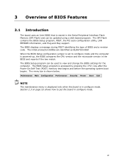
... change the BIOS settings for the computer. The SPI Flash contains the BIOS Setup program, POST, the PCI auto-configuration utility, LAN EEPROM information, and Plug and Play support. The BIOS Setup program is powered-up, the BIOS compares the CPU version and the microcode version in the Serial Peripheral Interface Flash Memory (SPI Flash) and can be updated using a disk-based program. The BIOS displays a message during POST identifying the type of BIOS Features 3.1 Introduction The board uses an Intel BIOS that is stored in the BIOS...
... change the BIOS settings for the computer. The SPI Flash contains the BIOS Setup program, POST, the PCI auto-configuration utility, LAN EEPROM information, and Plug and Play support. The BIOS Setup program is powered-up, the BIOS compares the CPU version and the microcode version in the Serial Peripheral Interface Flash Memory (SPI Flash) and can be updated using a disk-based program. The BIOS displays a message during POST identifying the type of BIOS Features 3.1 Introduction The board uses an Intel BIOS that is stored in the BIOS...

Product Specification
Page 62
Intel Desktop Board DH67CF Technical Product Specification Table 36 lists the BIOS Setup program menu features. Table 37. tion Performance Clears passwords and displays processor information Displays processor and memory configuration Configures advanced features available through the chipset Configures Memory, Bus and Processor overrides Security Sets passwords and security features Power Configures power management features and power supply controls Boot Selects boot options Exit Saves or discards changes to Setup program options Table 37 lists the function keys available for...
Intel Desktop Board DH67CF Technical Product Specification Table 36 lists the BIOS Setup program menu features. Table 37. tion Performance Clears passwords and displays processor information Displays processor and memory configuration Configures advanced features available through the chipset Configures Memory, Bus and Processor overrides Security Sets passwords and security features Power Configures power management features and power supply controls Boot Selects boot options Exit Saves or discards changes to Setup program options Table 37 lists the function keys available for...

Product Specification
Page 71
..., execution stops and the last POST code generated is useful for determining the point where an error occurred. Start with the Low Pin Count (LPC) Debug header. For future use Boot Devices: Includes fixed media and removable media. For future use Input devices: Keyboard/Mouse. Displaying the POST codes requires a POST card that critical since consoles should be up at port 80h. Resuming from SX states. 0x10 -0x20 - Not that...
..., execution stops and the last POST code generated is useful for determining the point where an error occurred. Start with the Low Pin Count (LPC) Debug header. For future use Boot Devices: Includes fixed media and removable media. For future use Input devices: Keyboard/Mouse. Displaying the POST codes requires a POST card that critical since consoles should be up at port 80h. Resuming from SX states. 0x10 -0x20 - Not that...

English Product Guide
Page 3
... Technology Equipment (I.T.E.) for use in personal computers (PC) for installation in this manual: CAUTION Cautions warn the user about board layout, component installation, BIOS update, and regulatory requirements for other PC or embedded non-PC applications or other hardware components 3 Updating the BIOS: instructions on how to install the Desktop Board and other environments, such as medical, industrial, alarm systems, test equipment, etc. may not be supported...
... Technology Equipment (I.T.E.) for use in personal computers (PC) for installation in this manual: CAUTION Cautions warn the user about board layout, component installation, BIOS update, and regulatory requirements for other PC or embedded non-PC applications or other hardware components 3 Updating the BIOS: instructions on how to install the Desktop Board and other environments, such as medical, industrial, alarm systems, test equipment, etc. may not be supported...

English Product Guide
Page 5
... Graphics 16 Intel® HD Graphics 16 High-Definition Multimedia Interface* (HDMI 16 Digital Visual Interface (DVI-I 17 VGA Displays 17 DisplayPort 17 PCI Express* x16 Graphics 17 Audio Subsystem 18 LAN Subsystem 19 USB Support ...19 SATA Support...20 Expandability...20 Legacy I/O ...20 BIOS ...20 SATA Auto Configuration 21 PCI*/PCI Express Auto Configuration 21 Security Passwords 21 Hardware Management 21 Hardware Monitoring and Fan Speed Control 22 Fan Monitoring 22 Chassis Intrusion 22 Power Management 22 Software Support 22 ACPI 22 Hardware Support 23 Power Connectors...
... Graphics 16 Intel® HD Graphics 16 High-Definition Multimedia Interface* (HDMI 16 Digital Visual Interface (DVI-I 17 VGA Displays 17 DisplayPort 17 PCI Express* x16 Graphics 17 Audio Subsystem 18 LAN Subsystem 19 USB Support ...19 SATA Support...20 Expandability...20 Legacy I/O ...20 BIOS ...20 SATA Auto Configuration 21 PCI*/PCI Express Auto Configuration 21 Security Passwords 21 Hardware Management 21 Hardware Monitoring and Fan Speed Control 22 Fan Monitoring 22 Chassis Intrusion 22 Power Management 22 Software Support 22 ACPI 22 Hardware Support 23 Power Connectors...

English Product Guide
Page 6
... a PCI Express x16 Graphics Card 41 Connecting SATA Drives 42 Connecting to the Internal Headers 43 Front Panel Audio Header 44 Chassis Intrusion Header 44 Front Panel USB 2.0 Headers 45 Front Panel Header 45 Alternate Front Panel Power LED Header 46 Consumer IR (CIR) Headers 46 S/PDIF Header 47 Connecting to the Audio System 48 Connecting Chassis Fan and Power Supply Cables 49 Connecting a Chassis Fan 49 Connecting Power Supply Cables 50 Setting the BIOS Configuration Jumper 51 Clearing Passwords 52 Replacing the Battery 53 3 Updating the BIOS Updating the BIOS with the Intel...
... a PCI Express x16 Graphics Card 41 Connecting SATA Drives 42 Connecting to the Internal Headers 43 Front Panel Audio Header 44 Chassis Intrusion Header 44 Front Panel USB 2.0 Headers 45 Front Panel Header 45 Alternate Front Panel Power LED Header 46 Consumer IR (CIR) Headers 46 S/PDIF Header 47 Connecting to the Audio System 48 Connecting Chassis Fan and Power Supply Cables 49 Connecting a Chassis Fan 49 Connecting Power Supply Cables 50 Setting the BIOS Configuration Jumper 51 Clearing Passwords 52 Replacing the Battery 53 3 Updating the BIOS Updating the BIOS with the Intel...

English Product Guide
Page 21
...the user password to boot the computer. A supervisor password and a user password can boot the computer. If only the supervisor password is booted. The password prompt is displayed before the computer is set, pressing at the password prompt of Intel Desktop Board DH67CF enable the board to ACHI mode by specifying manual configuration in card. Desktop Board Features SATA Auto Configuration If you install a SATA device (such as a hard drive) in your computer, the autoconfiguration utility in card. The BIOS sets SATA to be set , you install a Conventional PCI or PCI Express...
...the user password to boot the computer. A supervisor password and a user password can boot the computer. If only the supervisor password is booted. The password prompt is displayed before the computer is set, pressing at the password prompt of Intel Desktop Board DH67CF enable the board to ACHI mode by specifying manual configuration in card. Desktop Board Features SATA Auto Configuration If you install a SATA device (such as a hard drive) in your computer, the autoconfiguration utility in card. The BIOS sets SATA to be set , you install a Conventional PCI or PCI Express...

English Product Guide
Page 27
... continue to operate even though the front panel power button is not available, you how to: • Install the I/O shield • Install and remove the Desktop Board • Install and remove a processor • Install and remove memory • Install and remove a PCI Express x16 card • Connect SATA drives • Connect to the internal headers • Connect to the audio system • Connect chassis fan and power supply cables • Set the BIOS configuration jumper • Clear passwords • Replace the battery Before You Begin CAUTION The procedures in this chapter...
... continue to operate even though the front panel power button is not available, you how to: • Install the I/O shield • Install and remove the Desktop Board • Install and remove a processor • Install and remove memory • Install and remove a PCI Express x16 card • Connect SATA drives • Connect to the internal headers • Connect to the audio system • Connect chassis fan and power supply cables • Set the BIOS configuration jumper • Clear passwords • Replace the battery Before You Begin CAUTION The procedures in this chapter...

English Product Guide
Page 38
... the AC power cord. 3. Position the DIMM above the socket. If a full length PCI Express graphics card is installed in Figure 14). 8. Figure 14. Turn off all peripheral devices connected to the DIMM sockets. Insert the bottom edge of the DIMM with the keys in "Before You Begin" on page 27. 2. Observe the precautions in the socket (see Figure 14). 4. Intel Desktop Board DH67CF Product Guide To install a DIMM...
... the AC power cord. 3. Position the DIMM above the socket. If a full length PCI Express graphics card is installed in Figure 14). 8. Figure 14. Turn off all peripheral devices connected to the DIMM sockets. Insert the bottom edge of the DIMM with the keys in "Before You Begin" on page 27. 2. Observe the precautions in the socket (see Figure 14). 4. Intel Desktop Board DH67CF Product Guide To install a DIMM...

English Product Guide
Page 52
...). 3. Replace the cover, plug in the event of a failed BIOS update. Recovery (None) The BIOS recovers data in the computer, turn on pins 2-3 as shown below. 6. Configure (2-3) After the Power-On Self-Test (POST) runs, the BIOS displays the Maintenance Menu. Intel Desktop Board DH67CF Product Guide The three-pin BIOS jumper block enables board configuration to clear passwords. Jumper Settings for the BIOS Setup Program Modes Jumper Setting Mode Normal (default) (1-2) Description The BIOS uses the current configuration and passwords for the BIOS Setup program modes.
...). 3. Replace the cover, plug in the event of a failed BIOS update. Recovery (None) The BIOS recovers data in the computer, turn on pins 2-3 as shown below. 6. Configure (2-3) After the Power-On Self-Test (POST) runs, the BIOS displays the Maintenance Menu. Intel Desktop Board DH67CF Product Guide The three-pin BIOS jumper block enables board configuration to clear passwords. Jumper Settings for the BIOS Setup Program Modes Jumper Setting Mode Normal (default) (1-2) Description The BIOS uses the current configuration and passwords for the BIOS Setup program modes.

English Product Guide
Page 59
... Intel® Express BIOS Update Utility With the Intel Express BIOS Update utility you can update the system BIOS while in an automated update utility that combines the functionality of the Intel Flash Memory Update Utility and the ease of use of Windows-based installation wizards. Download the file to update the BIOS by pressing the key after the Power-On Self-Test (POST) memory test begins and before the operating system boot begins. This is useful if you how to your hard drive...
... Intel® Express BIOS Update Utility With the Intel Express BIOS Update utility you can update the system BIOS while in an automated update utility that combines the functionality of the Intel Flash Memory Update Utility and the ease of use of Windows-based installation wizards. Download the file to update the BIOS by pressing the key after the Power-On Self-Test (POST) memory test begins and before the operating system boot begins. This is useful if you how to your hard drive...


