

Technical Product Specification
Page 9
Major Board Components 13 2. Block Diagram 15 3. Connection Diagram for the Front Panel USB Header 46 12. Localized High Temperature Zones 52 Tables 1. LAN Connector LED States 24 7. Power States and Targeted System Power 29 ...Changes or Clarifications iii 2. Audio Jack Support 21 6. Wake-up Devices and Events 30 10. Back Panel Connectors 38 9. Connection Diagram for Front Panel Header 44 11. Feature Summary 11 3. Front Panel Audio Header for Intel HD Audio 41 14. Component-side Connectors and Headers 39 10. Supported Memory Configurations 18 5. SATA ...
Major Board Components 13 2. Block Diagram 15 3. Connection Diagram for the Front Panel USB Header 46 12. Localized High Temperature Zones 52 Tables 1. LAN Connector LED States 24 7. Power States and Targeted System Power 29 ...Changes or Clarifications iii 2. Audio Jack Support 21 6. Wake-up Devices and Events 30 10. Back Panel Connectors 38 9. Connection Diagram for Front Panel Header 44 11. Feature Summary 11 3. Front Panel Audio Header for Intel HD Audio 41 14. Component-side Connectors and Headers 39 10. Supported Memory Configurations 18 5. SATA ...

Technical Product Specification
Page 21
... page 39 1.10 Audio Subsystem The board supports Intel High Definition Audio through back panel jacks • Headphone and Mic in functions for the back panel audio jacks that enables the audio codec to recognize the device that is connected to an audio port. For information about The ...location of the front panel and back panel audio jacks. The back panel audio jacks are available from Intel's World Wide Web site. The serial port supports data transfers...
... page 39 1.10 Audio Subsystem The board supports Intel High Definition Audio through back panel jacks • Headphone and Mic in functions for the back panel audio jacks that enables the audio codec to recognize the device that is connected to an audio port. For information about The ...location of the front panel and back panel audio jacks. The back panel audio jacks are available from Intel's World Wide Web site. The serial port supports data transfers...

Technical Product Specification
Page 37
... memory Runtime BIOS Reserved Potential available high DOS memory (open to the computer's chassis. Do not use these groups: • Back panel I/O connectors • Component-side I/O connectors and headers (see page 39) 37 The connectors can be divided into these connectors or ... damage to the computer, the power cable, and the external devices themselves. This section describes the board's connectors. Furthermore, improper connection of USB header single wire connectors may eventually overload the overcurrent protection and cause damage to devices inside the computer's chassis, such...
... memory Runtime BIOS Reserved Potential available high DOS memory (open to the computer's chassis. Do not use these groups: • Back panel I/O connectors • Component-side I/O connectors and headers (see page 39) 37 The connectors can be divided into these connectors or ... damage to the computer, the power cable, and the external devices themselves. This section describes the board's connectors. Furthermore, improper connection of USB header single wire connectors may eventually overload the overcurrent protection and cause damage to devices inside the computer's chassis, such...

Technical Product Specification
Page 38
Poor audio quality occurs if passive (non-amplified) speakers are connected to power headphones or amplified speakers only. Intel Desktop Board DH61HO Technical Product Specification 2.2.1 Back Panel Connectors Figure 8 shows the location of the back panel connectors for the board. Item A B C D E F G H I Description PS/2 mouse connector PS/2 keyboard connector VGA connector UBS 2.0 ports LAN USB 2.0 ports Line in Line out/front speakers Mic in/side surround Figure 8. Back Panel Connectors NOTE The back panel audio line out connector is designed to this output. 38
Poor audio quality occurs if passive (non-amplified) speakers are connected to power headphones or amplified speakers only. Intel Desktop Board DH61HO Technical Product Specification 2.2.1 Back Panel Connectors Figure 8 shows the location of the back panel connectors for the board. Item A B C D E F G H I Description PS/2 mouse connector PS/2 keyboard connector VGA connector UBS 2.0 ports LAN USB 2.0 ports Line in Line out/front speakers Mic in/side surround Figure 8. Back Panel Connectors NOTE The back panel audio line out connector is designed to this output. 38

Technical Product Specification
Page 41
specifically, pins 4, 6, 7, and 10 are supported; Front Panel USB Header Pin Signal Name Pin 1 +5 VDC 2 3 D- 4 5 D+ 6 7 Ground 8 9 KEY (no pin) Table 13. Technical Reference 2.2.2.1 Signal Tables for Intel HD Audio Pin Signal Name Pin Signal Name 1 [Port 1] Left channel 2 Ground 3 [Port 1] ...DSR (Data Set Ready) 8 CTS (Clear To Send) 10 Key (no pin) 10 Signal Name +5 VDC DD+ Ground No Connect 41 Front Panel Audio Header for AC '97 Audio Pin Signal Name 1 MIC 3 MIC_BIAS 5 FP_OUT_R Pin Signal Name 2 AUD_GND 4 AUD_GND 6 FP_RETURN_R...
specifically, pins 4, 6, 7, and 10 are supported; Front Panel USB Header Pin Signal Name Pin 1 +5 VDC 2 3 D- 4 5 D+ 6 7 Ground 8 9 KEY (no pin) Table 13. Technical Reference 2.2.2.1 Signal Tables for Intel HD Audio Pin Signal Name Pin Signal Name 1 [Port 1] Left channel 2 Ground 3 [Port 1] ...DSR (Data Set Ready) 8 CTS (Clear To Send) 10 Key (no pin) 10 Signal Name +5 VDC DD+ Ground No Connect 41 Front Panel Audio Header for AC '97 Audio Pin Signal Name 1 MIC 3 MIC_BIAS 5 FP_OUT_R Pin Signal Name 2 AUD_GND 4 AUD_GND 6 FP_RETURN_R...
Technical Product Specification
Page 44
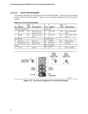
Table 20. Connection Diagram for the front panel header. Figure 10 is a connection diagram for Front Panel Header 44 Front Panel Header Pin Signal In/ Out Description Hard Drive Activity LED 1 HD_PWR Out Hard disk LED pull-up to +5 ...PWR# 8 Ground Not Connected 10 N/C In/ Out Description Out Front panel green LED Out Front panel yellow LED In Power switch Ground Not connected Figure 10. Table 20 lists the signal names of the front panel header. Intel Desktop Board DH61HO Technical Product Specification 2.2.2.4 Front Panel Header This section describes ...
Table 20. Connection Diagram for the front panel header. Figure 10 is a connection diagram for Front Panel Header 44 Front Panel Header Pin Signal In/ Out Description Hard Drive Activity LED 1 HD_PWR Out Hard disk LED pull-up to +5 ...PWR# 8 Ground Not Connected 10 N/C In/ Out Description Out Front panel green LED Out Front panel yellow LED In Power switch Ground Not connected Figure 10. Table 20 lists the signal names of the front panel header. Intel Desktop Board DH61HO Technical Product Specification 2.2.2.4 Front Panel Header This section describes ...

Technical Product Specification
Page 45
When the switch is closed, the board resets and runs the POST. 2.2.2.4.3 Power LED Header Pins 2 and 4 can be connected to a front panel momentary-contact power switch. The switch must pull the SW_ON# pin to ground for this LED. Table 21 shows the default states ... pass before the power supply will recognize another on/off /sleeping Steady Lit Running Blink Standby 2.2.2.4.4 Power Switch Header Pins 6 and 8 can be connected to a one- More options are available through BIOS setup. States for a One-Color Power LED LED State Description Off Power off signal. 45 ...
When the switch is closed, the board resets and runs the POST. 2.2.2.4.3 Power LED Header Pins 2 and 4 can be connected to a front panel momentary-contact power switch. The switch must pull the SW_ON# pin to ground for this LED. Table 21 shows the default states ... pass before the power supply will recognize another on/off /sleeping Steady Lit Running Blink Standby 2.2.2.4.4 Power Switch Header Pins 6 and 8 can be connected to a one- More options are available through BIOS setup. States for a One-Color Power LED LED State Description Off Power off signal. 45 ...
Technical Product Specification
Page 46
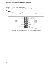
NOTE • The +5 V DC power on the USB header is a connection diagram for high-speed USB devices. Figure 11. Intel Desktop Board DH61HO Technical Product Specification 2.2.2.5 Front Panel USB Header Figure 11 is fused. • Use only a front panel USB connector that conforms to the USB 2.0 specification for the front panel USB header. Connection Diagram for the Front Panel USB Header 46
NOTE • The +5 V DC power on the USB header is a connection diagram for high-speed USB devices. Figure 11. Intel Desktop Board DH61HO Technical Product Specification 2.2.2.5 Front Panel USB Header Figure 11 is fused. • Use only a front panel USB connector that conforms to the USB 2.0 specification for the front panel USB header. Connection Diagram for the Front Panel USB Header 46


