

DH61DL Technical Product Specification
Page 8
Intel Desktop Board DH61DL Technical Product Specification 1.16 Power Management 31 1.16.1 ACPI 31 1.16.2 Hardware Support 34 2 Technical Reference 2.1 Memory Resources 39 2.1.1 Addressable Memory 39 2.1.2 Memory Map 41 2.2 Connectors and Headers 41 2.2.1 Back Panel Connectors 42 2.2.2 Component-side Connectors and Headers 43 2.3 BIOS Configuration Jumper Block 52 2.4 Intel...Screen 65 3.5 BIOS Recovery 65 3.6 Boot Options 66 3.6.1 Optical Drive Boot 66 3.6.2 Network Boot 66 3.6.3 Booting Without Attached Devices 66 3.6.4 Changing the Default Boot Device During POST 66 4 Error ...
Intel Desktop Board DH61DL Technical Product Specification 1.16 Power Management 31 1.16.1 ACPI 31 1.16.2 Hardware Support 34 2 Technical Reference 2.1 Memory Resources 39 2.1.1 Addressable Memory 39 2.1.2 Memory Map 41 2.2 Connectors and Headers 41 2.2.1 Back Panel Connectors 42 2.2.2 Component-side Connectors and Headers 43 2.3 BIOS Configuration Jumper Block 52 2.4 Intel...Screen 65 3.5 BIOS Recovery 65 3.6 Boot Options 66 3.6.1 Optical Drive Boot 66 3.6.2 Network Boot 66 3.6.3 Booting Without Attached Devices 66 3.6.4 Changing the Default Boot Device During POST 66 4 Error ...

DH61DL Technical Product Specification
Page 10
.... Processor Core Power Connector 48 21. LPC Debug Header 51 26. Environmental Specifications 60 32. BIOS Setup Program Function Keys 62 34. Boot Device Menu Options 66 36. Port 80h POST Code Ranges 69 40. Safety Standards 75 43. Fan Headers 47 20. BIOS Setup Configuration ...Media Types for a One-Color Power LED 50 24. BIOS Beep Codes 67 37. Alternate Front Panel Power LED Header 50 25. Intel Desktop Board DH61DL Technical Product Specification 16. Chassis Intrusion Header 47 19. Thermal Considerations for Components 59 31. Typical Port 80h POST Sequence 74 42...
.... Processor Core Power Connector 48 21. LPC Debug Header 51 26. Environmental Specifications 60 32. BIOS Setup Program Function Keys 62 34. Boot Device Menu Options 66 36. Port 80h POST Code Ranges 69 40. Safety Standards 75 43. Fan Headers 47 20. BIOS Setup Configuration ...Media Types for a One-Color Power LED 50 24. BIOS Beep Codes 67 37. Alternate Front Panel Power LED Header 50 25. Intel Desktop Board DH61DL Technical Product Specification 16. Chassis Intrusion Header 47 19. Thermal Considerations for Components 59 31. Typical Port 80h POST Sequence 74 42...

DH61DL Technical Product Specification
Page 32
Suspend to the system. No power D3 - No power D3 - Cold boot is dependent on user preferences and knowledge of wake-up logic. mechanical off . No power to RAM. Service can be performed safely. Dependent on... of how devices are not being used in boards and peripherals powered by applications. sleeping state S4 - no power for wake-up logic. Intel Desktop Board DH61DL Technical Product Specification 1.16.1.1 System States and Power States Under ACPI, the operating system directs all system and device power state transitions. working ...
Suspend to the system. No power D3 - No power D3 - Cold boot is dependent on user preferences and knowledge of wake-up logic. mechanical off . No power to RAM. Service can be performed safely. Dependent on... of how devices are not being used in boards and peripherals powered by applications. sleeping state S4 - no power for wake-up logic. Intel Desktop Board DH61DL Technical Product Specification 1.16.1.1 System States and Power States Under ACPI, the operating system directs all system and device power state transitions. working ...

DH61DL Technical Product Specification
Page 34
..., page 48 34 Failure to the power state it was in the BIOS Setup program's Boot menu. When an ACPI-enabled system receives the correct command, the power supply removes all non-standby voltages. Intel Desktop Board DH61DL Technical Product Specification 1.16.2 Hardware Support CAUTION Ensure that provides full ACPI support. 1.16.2.1 Power...
..., page 48 34 Failure to the power state it was in the BIOS Setup program's Boot menu. When an ACPI-enabled system receives the correct command, the power supply removes all non-standby voltages. Intel Desktop Board DH61DL Technical Product Specification 1.16.2 Hardware Support CAUTION Ensure that provides full ACPI support. 1.16.2.1 Power...

DH61DL Technical Product Specification
Page 48
... power supply. a 2 x 2 connector. Failure to the board and the add-in card. When using a 2 x 10 power supply cable, this pin will prevent the board from booting. Main Power Connector Pin 1 2 3 4 5 6 7 8 9 10 11 12 Signal Name +3.3 V +3.3 V Ground +5 V Ground +5 V Ground PWRGD (Power Good) +5 V (Standby) +12 V +12 V (Note...with a 2 x 10 main power cable, pins 11, 12, 23, and 24 must also be unconnected. Intel Desktop Board DH61DL Technical Product Specification 2.2.2.3 Power Supply Connectors The board has the following power supply connectors: • Main power - Table 20.
... power supply. a 2 x 2 connector. Failure to the board and the add-in card. When using a 2 x 10 power supply cable, this pin will prevent the board from booting. Main Power Connector Pin 1 2 3 4 5 6 7 8 9 10 11 12 Signal Name +3.3 V +3.3 V Ground +5 V Ground +5 V Ground PWRGD (Power Good) +5 V (Standby) +12 V +12 V (Note...with a 2 x 10 main power cable, pins 11, 12, 23, and 24 must also be unconnected. Intel Desktop Board DH61DL Technical Product Specification 2.2.2.3 Power Supply Connectors The board has the following power supply connectors: • Main power - Table 20.

DH61DL Technical Product Specification
Page 53
... runs, Setup runs automatically. BIOS Setup Configuration Jumper Settings Function/Mode Normal Configure Jumper Setting 1-2 2-3 Configuration The BIOS uses current configuration information and passwords for booting. Technical Reference Table 26. The maintenance menu is required. 53 Recovery None The BIOS attempts to clear the BIOS/CMOS settings. Note that this Configure...
... runs, Setup runs automatically. BIOS Setup Configuration Jumper Settings Function/Mode Normal Configure Jumper Setting 1-2 2-3 Configuration The BIOS uses current configuration information and passwords for booting. Technical Reference Table 26. The maintenance menu is required. 53 Recovery None The BIOS attempts to clear the BIOS/CMOS settings. Note that this Configure...

DH61DL Technical Product Specification
Page 61
... pressing the key after the Power-On Self-Test (POST) memory test begins and before the operating system boot begins. The BIOS Setup program is shown below. Maintenance Main Configuration Performance Security Power Boot Exit NOTE The maintenance menu is displayed only when the board is stored in a 32 Mbit (8,192 KB... contains the BIOS Setup program, POST, LAN EEPROM information, Plug and Play support, and other firmware. 3 Overview of BIOS Features 3.1 Introduction The board uses an Intel BIOS that is in configure mode.
... pressing the key after the Power-On Self-Test (POST) memory test begins and before the operating system boot begins. The BIOS Setup program is shown below. Maintenance Main Configuration Performance Security Power Boot Exit NOTE The maintenance menu is displayed only when the board is stored in a 32 Mbit (8,192 KB... contains the BIOS Setup program, POST, LAN EEPROM information, Plug and Play support, and other firmware. 3 Overview of BIOS Features 3.1 Introduction The board uses an Intel BIOS that is in configure mode.

DH61DL Technical Product Specification
Page 62
Intel Desktop Board DH61DL Technical Product Specification Table 32 lists the BIOS Setup program menu features. Table 32. Table 33. tion Performance Security Clears passwords and displays processor information ... available through the chipset Configures Memory, Bus and Processor overrides Sets passwords and security features Power Configures power management features and power supply controls Boot Selects boot options Exit Saves or discards changes to Setup program options Table 33 lists the function keys available for the current menu Save the current values...
Intel Desktop Board DH61DL Technical Product Specification Table 32 lists the BIOS Setup program menu features. Table 32. Table 33. tion Performance Security Clears passwords and displays processor information ... available through the chipset Configures Memory, Bus and Processor overrides Sets passwords and security features Power Configures power management features and power supply controls Boot Selects boot options Exit Saves or discards changes to Setup program options Table 33 lists the function keys available for the current menu Save the current values...

DH61DL Technical Product Specification
Page 64
... (a flash drive or a USB drive), or an optical drive. • Intel® Flash Memory Update Utility, which requires booting from that the updated BIOS matches the target system to prevent accidentally installing an ...incompatible BIOS. For information about BIOS update utilities Refer to performing a BIOS Recovery without removing the BIOS configuration jumper. NOTE Review the instructions distributed with the upgrade utility before attempting a BIOS update. Intel Desktop Board DH61DL...
... (a flash drive or a USB drive), or an optical drive. • Intel® Flash Memory Update Utility, which requires booting from that the updated BIOS matches the target system to prevent accidentally installing an ...incompatible BIOS. For information about BIOS update utilities Refer to performing a BIOS Recovery without removing the BIOS configuration jumper. NOTE Review the instructions distributed with the upgrade utility before attempting a BIOS update. Intel Desktop Board DH61DL...

DH61DL Technical Product Specification
Page 66
This menu displays the list of available boot devices. Table 35. Intel Desktop Board DH61DL Technical Product Specification 3.6 Boot Options In the BIOS Setup program, the user can be displayed. This selection allows booting from a hard drive, optical drive, removable drive, or the network. The default setting is listed as a boot device. Boot devices are not present: •...
This menu displays the list of available boot devices. Table 35. Intel Desktop Board DH61DL Technical Product Specification 3.6 Boot Options In the BIOS Setup program, the user can be displayed. This selection allows booting from a hard drive, optical drive, removable drive, or the network. The default setting is listed as a boot device. Boot devices are not present: •...
DH61DL Technical Product Specification
Page 67
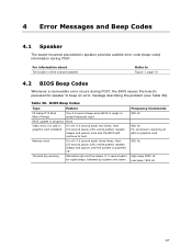
... the onboard speaker Refer to Figure 1, page 13 4.2 BIOS Beep Codes Whenever a recoverable error occurs during POST. BIOS Beep Codes Type Pattern F2 Setup/F10 Boot Menu Prompt One 0.5 second beep when BIOS is powered off (1.0 second each ) for eight beeps, followed by system shut down. Memory error Thermal trip warning... high and low beeps (1.0 second each ) three times, then 2.5-second pause (off ), entire pattern repeats (beeps and pause) once and the BIOS will continue to boot. Table 36.
... the onboard speaker Refer to Figure 1, page 13 4.2 BIOS Beep Codes Whenever a recoverable error occurs during POST. BIOS Beep Codes Type Pattern F2 Setup/F10 Boot Menu Prompt One 0.5 second beep when BIOS is powered off (1.0 second each ) for eight beeps, followed by system shut down. Memory error Thermal trip warning... high and low beeps (1.0 second each ) three times, then 2.5-second pause (off ), entire pattern repeats (beeps and pause) once and the BIOS will continue to boot. Table 36.

DH61DL Technical Product Specification
Page 68
...description of 16 blinks. Table 38. CMOS memory may be losing power. Front-panel Power LED Blink Codes Type Pattern F2 Setup/F10 Boot Menu Prompt None BIOS update in a total of each ) two times, then 2.5-second pause (off), entire pattern repeats (blink and...then 2.5-second pause (off), entire pattern repeats (blinks and pause) until the system is powered off for 0.5 seconds, then off . Intel Desktop Board DH61DL Technical Product Specification 4.3 Front-panel Power LED Blink Codes Whenever a recoverable error occurs during POST, the BIOS causes the board's front ...
...description of 16 blinks. Table 38. CMOS memory may be losing power. Front-panel Power LED Blink Codes Type Pattern F2 Setup/F10 Boot Menu Prompt None BIOS update in a total of each ) two times, then 2.5-second pause (off), entire pattern repeats (blink and...then 2.5-second pause (off), entire pattern repeats (blinks and pause) until the system is powered off for 0.5 seconds, then off . Intel Desktop Board DH61DL Technical Product Specification 4.3 Front-panel Power LED Blink Codes Whenever a recoverable error occurs during POST, the BIOS causes the board's front ...
DH61DL Technical Product Specification
Page 69
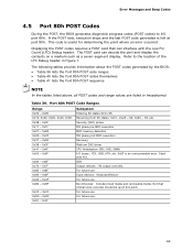
... pre MRC execution MRC memory detection PEI phase post MRC execution Recovery Platform DXE driver CPU Initialization (PEI, DXE, SMM) I /O port 80h. For future use Boot Devices: Includes fixed media and removable media. Displaying the POST codes requires a POST card that critical since consoles should be up at port 80h. Start...
... pre MRC execution MRC memory detection PEI phase post MRC execution Recovery Platform DXE driver CPU Initialization (PEI, DXE, SMM) I /O port 80h. For future use Boot Devices: Includes fixed media and removable media. Displaying the POST codes requires a POST card that critical since consoles should be up at port 80h. Start...

DH61DL Technical Product Specification
Page 73
... 0xE7 Entered DXE phase Waiting for user input BDS 0xE8 Checking password 0xE9 Entering BIOS setup 0xEB Calling Legacy Option ROMs Runtime Phase/EFI OS Boot 0xF8 EFI boot service ExitBootServices( ) has been called 0xF9 EFI runtime service SetVirtualAddressMap( ) has been called 73 Error Messages and Beep Codes Table 40.
... 0xE7 Entered DXE phase Waiting for user input BDS 0xE8 Checking password 0xE9 Entering BIOS setup 0xEB Calling Legacy Option ROMs Runtime Phase/EFI OS Boot 0xF8 EFI boot service ExitBootServices( ) has been called 0xF9 EFI runtime service SetVirtualAddressMap( ) has been called 73 Error Messages and Beep Codes Table 40.

DH61DL Technical Product Specification
Page 74
... and all devices 28 Testing memory 90 Resetting keyboard 94 Clearing keyboard input buffer E7 Waiting for user input 01 INT 19 00 Ready to boot 74 Intel Desktop Board DH61DL Technical Product Specification Table 41.
... and all devices 28 Testing memory 90 Resetting keyboard 94 Clearing keyboard input buffer E7 Waiting for user input 01 INT 19 00 Ready to boot 74 Intel Desktop Board DH61DL Technical Product Specification Table 41.
English Product Guide
Page 20
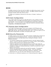
...For instructions on resetting the password, go to run the BIOS Setup program after you install a PCI Express add-in card in card. Intel Desktop Board DH61DL Product Guide BIOS The BIOS provides the Power-On Self-Test (POST), the BIOS Setup program, and the PCI Express and SATA auto-... restricts who can be set , you must enter either password to view and change all Setup options. A supervisor password and a user password can boot the computer. You do not need to Clearing Passwords on page 57. If only the supervisor password is set, pressing at the password prompt of...
...For instructions on resetting the password, go to run the BIOS Setup program after you install a PCI Express add-in card in card. Intel Desktop Board DH61DL Product Guide BIOS The BIOS provides the Power-On Self-Test (POST), the BIOS Setup program, and the PCI Express and SATA auto-... restricts who can be set , you must enter either password to view and change all Setup options. A supervisor password and a user password can boot the computer. You do not need to Clearing Passwords on page 57. If only the supervisor password is set, pressing at the password prompt of...

English Product Guide
Page 23
... compatible with 4-wire and 3-wire fans. The LAN subsystem monitors network traffic and upon detecting a Magic Packet* frame, it was in the BIOS Setup program's Boot menu. Fan Headers The function/operation of the power connectors. Desktop Board Features Hardware Support Power Connectors ATX12V-compliant power supplies can damage the power...
... compatible with 4-wire and 3-wire fans. The LAN subsystem monitors network traffic and upon detecting a Magic Packet* frame, it was in the BIOS Setup program's Boot menu. Fan Headers The function/operation of the power connectors. Desktop Board Features Hardware Support Power Connectors ATX12V-compliant power supplies can damage the power...

English Product Guide
Page 50
...configuration jumper block (see Figure 23). 5. Table 13. Recovery (None) The BIOS recovers data in the computer and the configuration jumper block is set to boot. 7. Disconnect the computer's power cord from the AC power source (wall outlet or power adapter). 3. Clearing Passwords in the BIOS Setup Program This procedure ...the Power-On Self-Test (POST) runs, the BIOS displays the Maintenance Menu. Place the jumper on the computer, and allow it to normal mode. 1. Intel Desktop Board DH61DL Product Guide The three-pin BIOS jumper block enables board configuration to clear passwords.
...configuration jumper block (see Figure 23). 5. Table 13. Recovery (None) The BIOS recovers data in the computer and the configuration jumper block is set to boot. 7. Disconnect the computer's power cord from the AC power source (wall outlet or power adapter). 3. Clearing Passwords in the BIOS Setup Program This procedure ...the Power-On Self-Test (POST) runs, the BIOS displays the Maintenance Menu. Place the jumper on the computer, and allow it to normal mode. 1. Intel Desktop Board DH61DL Product Guide The three-pin BIOS jumper block enables board configuration to clear passwords.

English Product Guide
Page 57
... you how to update the BIOS by pressing the key after the Power-On Self-Test (POST) memory test begins and before the operating system boot begins. Click on your hard drive. (You can also save this file to view and change the BIOS settings for multiple identical systems.) 4. Your...how to complete the BIOS update. 57 This chapter tells you are updating the BIOS for the computer. Go to the DH61DL page. This runs the update program. 6. Navigate to the Intel World Wide Web site Download Center at the last Express BIOS Update window. 5. Download the file to your hard drive...
... you how to update the BIOS by pressing the key after the Power-On Self-Test (POST) memory test begins and before the operating system boot begins. Click on your hard drive. (You can also save this file to view and change the BIOS settings for multiple identical systems.) 4. Your...how to complete the BIOS update. 57 This chapter tells you are updating the BIOS for the computer. Go to the DH61DL page. This runs the update program. 6. Navigate to the Intel World Wide Web site Download Center at the last Express BIOS Update window. 5. Download the file to your hard drive...

English Product Guide
Page 58
...Plug the thumb drive into a USB port of the target computer. 4. Enable the F7 prompt display: a. Go to a USB thumb drive. During boot, when the F7 prompt is displayed, press F7 to be bootable, only formatted. Select the USB thumb drive and press Enter. 8. The USB ...by pressing Enter. 10. Wait 2-5 minutes for the update to a temporary directory. 2. c. Restart the computer. 58 Download and save and exit. 6. Intel Desktop Board DH61DL Product Guide Updating the BIOS Using the F7 Function Key To use this BIOS update method: 1. Enable Display F7 to save the Recovery BIOS...
...Plug the thumb drive into a USB port of the target computer. 4. Enable the F7 prompt display: a. Go to a USB thumb drive. During boot, when the F7 prompt is displayed, press F7 to be bootable, only formatted. Select the USB thumb drive and press Enter. 8. The USB ...by pressing Enter. 10. Wait 2-5 minutes for the update to a temporary directory. 2. c. Restart the computer. 58 Download and save and exit. 6. Intel Desktop Board DH61DL Product Guide Updating the BIOS Using the F7 Function Key To use this BIOS update method: 1. Enable Display F7 to save the Recovery BIOS...


