
Technical Product Specification
Page 7
...Express Chipset 17 1.6 System Memory 17 1.6.1 Memory Configurations 18 1.7 Graphics Subsystem 20 1.7.1 Integrated Graphics 20 1.7.2 PCI Express x16 Graphics 20 1.8 USB 21 1.9 SATA Interfaces 21 1.10 Legacy I/O Controller 22 1.10.1 Serial Port 22 1.11 Audio Subsystem 23 1.11.1 Audio Subsystem Software 24... 1.11.2 Audio Headers and Connectors 24 1.12 LAN Subsystem 26 1.12.1 Intel® 82579V Gigabit Ethernet Controller 26 1.12.2 LAN Subsystem Software 26 1.12.3 RJ-45 LAN Connector with Integrated LEDs 27 1.13 Real-...
...Express Chipset 17 1.6 System Memory 17 1.6.1 Memory Configurations 18 1.7 Graphics Subsystem 20 1.7.1 Integrated Graphics 20 1.7.2 PCI Express x16 Graphics 20 1.8 USB 21 1.9 SATA Interfaces 21 1.10 Legacy I/O Controller 22 1.10.1 Serial Port 22 1.11 Audio Subsystem 23 1.11.1 Audio Subsystem Software 24... 1.11.2 Audio Headers and Connectors 24 1.12 LAN Subsystem 26 1.12.1 Intel® 82579V Gigabit Ethernet Controller 26 1.12.2 LAN Subsystem Software 26 1.12.3 RJ-45 LAN Connector with Integrated LEDs 27 1.13 Real-...
Technical Product Specification
Page 8
Intel Desktop Board DH61BE Technical Product Specification 1.15 Platform Management and Security 30 1.15.1 Hardware Management Subsystem 30 1.15.2 Hardware Monitoring 30 1.16 Power ...Intel® MEBX) Reset Header 54 2.5 Mechanical Considerations 55 2.5.1 Form Factor 55 2.6 Electrical Considerations 56 2.6.1 Power Supply Considerations 56 2.6.2 Fan Header Current Capability 57 2.6.3 Add-in Board Considerations 57 2.7 Thermal Considerations 58 2.8 Reliability 60 2.9 Environmental 60 3 Overview of BIOS Features 3.1 Introduction 61 3.2 System Management BIOS (SMBIOS 63 3.3 Legacy USB...
Intel Desktop Board DH61BE Technical Product Specification 1.15 Platform Management and Security 30 1.15.1 Hardware Management Subsystem 30 1.15.2 Hardware Monitoring 30 1.16 Power ...Intel® MEBX) Reset Header 54 2.5 Mechanical Considerations 55 2.5.1 Form Factor 55 2.6 Electrical Considerations 56 2.6.1 Power Supply Considerations 56 2.6.2 Fan Header Current Capability 57 2.6.3 Add-in Board Considerations 57 2.7 Thermal Considerations 58 2.8 Reliability 60 2.9 Environmental 60 3 Overview of BIOS Features 3.1 Introduction 61 3.2 System Management BIOS (SMBIOS 63 3.3 Legacy USB...
Technical Product Specification
Page 9
...Pressing the Power Switch 31 7. LAN Connector LED States 27 6. Internal Mono Speaker Header 45 15. Front Panel Audio Header for Front Panel USB Headers 51 13. Supported Memory Configurations 18 4. S/PDIF Header 45 14. LAN Connector LED Locations 27 6. Components Shown in Figure 10 44 ...Back Panel Connectors 42 10. Power States and Targeted System Power 32 8. Wake-up Devices and Events 33 9. Connection Diagram for Intel HD Audio 46 ix Intel MEBX Reset Header 54 15. System Memory Map 41 10. Connection Diagram for Front Panel Header 49 12. Major Board Components ...
...Pressing the Power Switch 31 7. LAN Connector LED States 27 6. Internal Mono Speaker Header 45 15. Front Panel Audio Header for Front Panel USB Headers 51 13. Supported Memory Configurations 18 4. S/PDIF Header 45 14. LAN Connector LED Locations 27 6. Components Shown in Figure 10 44 ...Back Panel Connectors 42 10. Power States and Targeted System Power 32 8. Wake-up Devices and Events 33 9. Connection Diagram for Intel HD Audio 46 ix Intel MEBX Reset Header 54 15. System Memory Map 41 10. Connection Diagram for Front Panel Header 49 12. Major Board Components ...
Technical Product Specification
Page 10
...POST Codes 70 42. Front Panel Header 49 24. BIOS Beep Codes 67 38. Port 80h POST Code Ranges 69 41. Intel Desktop Board DH61BE Technical Product Specification 16. BIOS Setup Configuration Jumper Settings 53 28. BIOS Setup Program Menu Bar 62 34. States for Components 59... 32. Regulatory Compliance Marks 83 x Main Power Connector 48 23. LPC Debug Header 51 27. Front Panel USB Header 46 18. ...
...POST Codes 70 42. Front Panel Header 49 24. BIOS Beep Codes 67 38. Port 80h POST Code Ranges 69 41. Intel Desktop Board DH61BE Technical Product Specification 16. BIOS Setup Configuration Jumper Settings 53 28. BIOS Setup Program Menu Bar 62 34. States for Components 59... 32. Regulatory Compliance Marks 83 x Main Power Connector 48 23. LPC Debug Header 51 27. Front Panel USB Header 46 18. ...
Technical Product Specification
Page 12
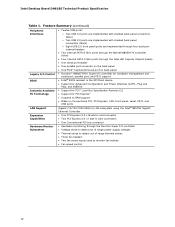
...Intel Desktop Board DH61BE Technical Product Specification Table 1. Feature Summary (continued) Peripheral Interfaces Legacy I/O Control BIOS • Twelve USB ports: ― Two USB 3.0 ports are implemented with stacked back panel connectors (blue) ― Two USB 2.0 ports are implemented with stacked back panel connectors (black) ― Eight USB...8226; Wake on Conventional PCI, PCI Express, LAN, front panel, serial, PS/2, and USB ports Gigabit (10/100/1000 Mbits/s) LAN subsystem using the Intel® 82579V Gigabit Ethernet Controller • One PCI Express 2.0 x16 add-in card ...
...Intel Desktop Board DH61BE Technical Product Specification Table 1. Feature Summary (continued) Peripheral Interfaces Legacy I/O Control BIOS • Twelve USB ports: ― Two USB 3.0 ports are implemented with stacked back panel connectors (blue) ― Two USB 2.0 ports are implemented with stacked back panel connectors (black) ― Eight USB...8226; Wake on Conventional PCI, PCI Express, LAN, front panel, serial, PS/2, and USB ports Gigabit (10/100/1000 Mbits/s) LAN subsystem using the Intel® 82579V Gigabit Ethernet Controller • One PCI Express 2.0 x16 add-in card ...
Technical Product Specification
Page 14
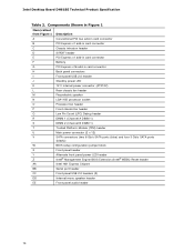
...header PCI Express x1 add-in card connector Battery PCI Express x16 add-in card connector Back panel connectors Front panel USB 2.0 header Standby power LED 12 V internal power connector (ATX12V) Rear chassis fan header Piezoelectric speaker LGA1155 processor socket ... header Alternate front panel power LED header Intel® Management Engine BIOS Extension (Intel® MEBX) Reset header Intel H61 Express Chipset Serial port header Front panel USB 2.0 headers (3) Internal mono speaker header Front panel audio header 14 Intel Desktop Board DH61BE Technical Product Specification Table 2.
...header PCI Express x1 add-in card connector Battery PCI Express x16 add-in card connector Back panel connectors Front panel USB 2.0 header Standby power LED 12 V internal power connector (ATX12V) Rear chassis fan header Piezoelectric speaker LGA1155 processor socket ... header Alternate front panel power LED header Intel® Management Engine BIOS Extension (Intel® MEBX) Reset header Intel H61 Express Chipset Serial port header Front panel USB 2.0 headers (3) Internal mono speaker header Front panel audio header 14 Intel Desktop Board DH61BE Technical Product Specification Table 2.
Technical Product Specification
Page 17
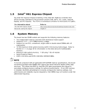
...determined frequency. 17 Refer to Section 2.1.1 on page 39 for information on the total amount of the Intel H61 Platform Controller Hub (PCH) provides interfaces to http://www.intel.com/products/desktop/chipsets/index.htm Chapter 2 1.6 System Memory The board has two DIMM sockets and ... memory technology). If non-SPD memory is a centralized controller for optimum performance. For information about The Intel H61 Express chipset Resources used by the chipset Refer to the processor and the USB, SATA, LPC, audio, network, display, and PCI Express. The PCH is installed, the BIOS ...
...determined frequency. 17 Refer to Section 2.1.1 on page 39 for information on the total amount of the Intel H61 Platform Controller Hub (PCH) provides interfaces to http://www.intel.com/products/desktop/chipsets/index.htm Chapter 2 1.6 System Memory The board has two DIMM sockets and ... memory technology). If non-SPD memory is a centralized controller for optimum performance. For information about The Intel H61 Express chipset Resources used by the chipset Refer to the processor and the USB, SATA, LPC, audio, network, display, and PCI Express. The PCH is installed, the BIOS ...
Technical Product Specification
Page 21
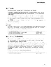
...Gb/s ports through four dual-port internal headers All 12 USB ports are provided by the NEC UPD720200 controller. The SATA controller can operate in both legacy and native modes. The Intel H61 Express Chipset provides the USB controller for configurations using the Windows* XP, Windows Vista*, ...and Windows 7* operating systems. For more information, see: http://www.serialata.org/. The USB 3.0 ports are assigned (IRQ 14 and 15)....
...Gb/s ports through four dual-port internal headers All 12 USB ports are provided by the NEC UPD720200 controller. The SATA controller can operate in both legacy and native modes. The Intel H61 Express Chipset provides the USB controller for configurations using the Windows* XP, Windows Vista*, ...and Windows 7* operating systems. For more information, see: http://www.serialata.org/. The USB 3.0 ports are assigned (IRQ 14 and 15)....
Technical Product Specification
Page 31
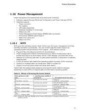
... ACPI support. working state) Less than four seconds Wake-up support PCI Express WAKE# signal support Wake from serial port Wake from USB Power Management Event signal (PME#) wake-up (ACPI G0 - working state) Sleep (ACPI G1 - Soft off ) Note: System can only enter Standby state if...
... ACPI support. working state) Less than four seconds Wake-up support PCI Express WAKE# signal support Wake from serial port Wake from USB Power Management Event signal (PME#) wake-up (ACPI G0 - working state) Sleep (ACPI G1 - Soft off ) Note: System can only enter Standby state if...

Technical Product Specification
Page 33
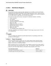
... provides full ACPI support. Table 8. Product Description 1.16.1.2 Wake-up the computer... Power switch RTC alarm LAN USB PME# signal WAKE# signal Serial port PS/2 Notes: • S4 implies operating system support only. • USB ports are turned off during S4/S5 states. ...from this state S3, S4, S5 S3, S4, S5...
... provides full ACPI support. Table 8. Product Description 1.16.1.2 Wake-up the computer... Power switch RTC alarm LAN USB PME# signal WAKE# signal Serial port PS/2 Notes: • S4 implies operating system support only. • USB ports are turned off during S4/S5 states. ...from this state S3, S4, S5 S3, S4, S5...
Technical Product Specification
Page 34
... hardware features, including: • Power connector • Fan headers • LAN wake capabilities • Instantly Available PC technology • Wake from USB • PME# signal wake-up support • WAKE# signal wake-up support • Wake from serial port • Wake from PS/2 &#... to the power state it was in the BIOS Setup program's Boot menu. When resuming from the +5 V standby line. Intel Desktop Board DH61BE Technical Product Specification 1.16.2 Hardware Support CAUTION Ensure that provides full ACPI support. 1.16.2.1 Power Connector ATX12V-compliant power supplies ...
... hardware features, including: • Power connector • Fan headers • LAN wake capabilities • Instantly Available PC technology • Wake from USB • PME# signal wake-up support • WAKE# signal wake-up support • Wake from serial port • Wake from PS/2 &#... to the power state it was in the BIOS Setup program's Boot menu. When resuming from the +5 V standby line. Intel Desktop Board DH61BE Technical Product Specification 1.16.2 Hardware Support CAUTION Ensure that provides full ACPI support. 1.16.2.1 Power Connector ATX12V-compliant power supplies ...
Technical Product Specification
Page 36
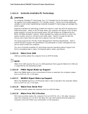
Intel Desktop Board DH61BE Technical Product Specification 1.16.2.4 Instantly Available PC Technology CAUTION For Instantly Available PC technology, the +5 V standby line for the power supply must be capable of a USB peripheral that supports Wake from USB and is supported by the operating system. 1.16.2.6 PME# Signal Wake-up Support ... supply is off and the front panel power LED will wake the computer is in cards, and drivers. 1.16.2.5 Wake from USB USB bus activity wakes the computer from the S3 state. While in power management and can participate in the S3 sleep-state, the computer...
Intel Desktop Board DH61BE Technical Product Specification 1.16.2.4 Instantly Available PC Technology CAUTION For Instantly Available PC technology, the +5 V standby line for the power supply must be capable of a USB peripheral that supports Wake from USB and is supported by the operating system. 1.16.2.6 PME# Signal Wake-up Support ... supply is off and the front panel power LED will wake the computer is in cards, and drivers. 1.16.2.5 Wake from USB USB bus activity wakes the computer from the S3 state. While in power management and can participate in the S3 sleep-state, the computer...
Technical Product Specification
Page 41
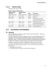
...) Extended conventional memory Conventional memory 2.2 Connectors and Headers CAUTION Only the following connectors and headers have overcurrent protection: back panel and front panel USB, and PS/2. C7FFF 9FC00 - 9FFFF 80000 - 9FBFF 00000 - 7FFFF Size 16382 MB 64 KB 64 KB 96 KB 160 KB 1... by the external devices could cause damage to the PCI bus). This section describes the board's connectors. Furthermore, improper connection of USB header single wire connectors may eventually overload the overcurrent protection and cause damage to devices inside the computer's chassis, such as fans ...
...) Extended conventional memory Conventional memory 2.2 Connectors and Headers CAUTION Only the following connectors and headers have overcurrent protection: back panel and front panel USB, and PS/2. C7FFF 9FC00 - 9FFFF 80000 - 9FBFF 00000 - 7FFFF Size 16382 MB 64 KB 64 KB 96 KB 160 KB 1... by the external devices could cause damage to the PCI bus). This section describes the board's connectors. Furthermore, improper connection of USB header single wire connectors may eventually overload the overcurrent protection and cause damage to devices inside the computer's chassis, such as fans ...

Technical Product Specification
Page 42
... amplified speakers only. Item A B C D E F G H I J K L M Description PS/2 keyboard/mouse connector USB 2.0 ports VGA connector Parallel port DVI-D connector LAN USB 3.0 ports Rear surround Center channel and LFE (subwoofer) S/PDIF out (optical) Line in Line out/front speakers Mic in/side surround Figure 9. Intel Desktop Board DH61BE Technical Product Specification 2.2.1 Back Panel Connectors Figure 9 shows the...
... amplified speakers only. Item A B C D E F G H I J K L M Description PS/2 keyboard/mouse connector USB 2.0 ports VGA connector Parallel port DVI-D connector LAN USB 3.0 ports Rear surround Center channel and LFE (subwoofer) S/PDIF out (optical) Line in Line out/front speakers Mic in/side surround Figure 9. Intel Desktop Board DH61BE Technical Product Specification 2.2.1 Back Panel Connectors Figure 9 shows the...

Technical Product Specification
Page 44
... D S/PDIF header E PCI Express x1 add-in card connector F PCI Express x16 bus add-in card connector G Front panel USB 2.0 header H 12 V internal power connector (ATX12V) I Rear chassis fan header J Processor fan header K Front chassis fan header...panel header Q Alternate front panel power LED header R Intel MEBX Reset header S Serial port header T Front panel USB 2.0 header U Front panel USB 2.0 header V Front panel USB 2.0 header W Internal mono speaker header X Front panel audio header 44 Intel Desktop Board DH61BE Technical Product Specification Table 10.
... D S/PDIF header E PCI Express x1 add-in card connector F PCI Express x16 bus add-in card connector G Front panel USB 2.0 header H 12 V internal power connector (ATX12V) I Rear chassis fan header J Processor fan header K Front chassis fan header...panel header Q Alternate front panel power LED header R Intel MEBX Reset header S Serial port header T Front panel USB 2.0 header U Front panel USB 2.0 header V Front panel USB 2.0 header W Internal mono speaker header X Front panel audio header 44 Intel Desktop Board DH61BE Technical Product Specification Table 10.

Technical Product Specification
Page 46
...AUD_5V 8 KEY (no pin) 9 FP_OUT_L 10 FP_RETURN_L NOTE Not all AC '97 signals are not supported. Table 17. Front Panel Audio Header for Intel HD Audio Pin Signal Name Pin Signal Name 1 [Port 1] Left channel 2 Ground 3 [Port 1] Right channel 4 PRESENCE# (Dongle present) 5...Port 2] Right channel 6 [Port 1] SENSE_RETURN 7 SENSE_SEND (Jack detection) 8 Key (no pin) 10 Signal Name +5 VDC DD+ Ground No Connect Table 18. Front Panel USB Header Pin Signal Name Pin 1 +5 VDC 2 3 D- 4 5 D+ 6 7 Ground 8 9 KEY (no pin) 9 [Port 2] Left channel 10 [Port 2]...
...AUD_5V 8 KEY (no pin) 9 FP_OUT_L 10 FP_RETURN_L NOTE Not all AC '97 signals are not supported. Table 17. Front Panel Audio Header for Intel HD Audio Pin Signal Name Pin Signal Name 1 [Port 1] Left channel 2 Ground 3 [Port 1] Right channel 4 PRESENCE# (Dongle present) 5...Port 2] Right channel 6 [Port 1] SENSE_RETURN 7 SENSE_SEND (Jack detection) 8 Key (no pin) 10 Signal Name +5 VDC DD+ Ground No Connect Table 18. Front Panel USB Header Pin Signal Name Pin 1 +5 VDC 2 3 D- 4 5 D+ 6 7 Ground 8 9 KEY (no pin) 9 [Port 2] Left channel 10 [Port 2]...
Technical Product Specification
Page 51
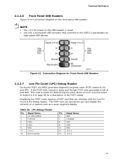
... the port and display the contents on page 69 for the front panel USB headers. NOTE • The +5 V DC power on the USB headers is useful for high-speed USB devices. Connection Diagram for Front Panel USB Headers 2.2.2.7 Low Pin Count (LPC) Debug Header During the POST, the... such as a seven-segment display. The POST card can interface with the Low Pin Count (LPC) Debug header. Table 26. Technical Reference 2.2.2.6 Front Panel USB Headers Figure 12 is left at port 80h. LPC Debug Header Pin Signal Name 1 CK_33M_DEBUG 3 PLTRST# 5 LAD0 7 LAD2 9 GND 11 +3.3 V 13...
... the port and display the contents on page 69 for the front panel USB headers. NOTE • The +5 V DC power on the USB headers is useful for high-speed USB devices. Connection Diagram for Front Panel USB Headers 2.2.2.7 Low Pin Count (LPC) Debug Header During the POST, the... such as a seven-segment display. The POST card can interface with the Low Pin Count (LPC) Debug header. Table 26. Technical Reference 2.2.2.6 Front Panel USB Headers Figure 12 is left at port 80h. LPC Debug Header Pin Signal Name 1 CK_33M_DEBUG 3 PLTRST# 5 LAD0 7 LAD2 9 GND 11 +3.3 V 13...
Technical Product Specification
Page 53
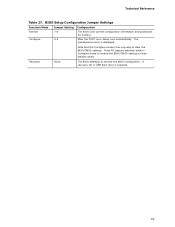
... recover the BIOS configuration. Recovery None The BIOS attempts to clear the BIOS/CMOS settings. After the POST runs, Setup runs automatically. A recovery CD or USB flash drive is displayed. Press F9 (restore defaults) while in Configure mode to restore the BIOS/CMOS settings to their default values. Technical Reference Table...
... recover the BIOS configuration. Recovery None The BIOS attempts to clear the BIOS/CMOS settings. After the POST runs, Setup runs automatically. A recovery CD or USB flash drive is displayed. Press F9 (restore defaults) while in Configure mode to restore the BIOS/CMOS settings to their default values. Technical Reference Table...

Technical Product Specification
Page 54
...allowed to the default value (admin). Intel Desktop Board DH61BE Technical Product Specification 2.4 Intel® Management Engine BIOS Extension (Intel® MEBX) Reset Header The Intel® MEBX reset header (see Figure 14) allows you to reset the Intel AMT configuration to their default values. ...pins 1 and 2 with a jumper (not supplied) will be damaged. 54 USB key and remote configuration data will accomplish the following: • Return all Intel ME parameters to the factory defaults. Intel MEBX Reset Header Signals Pin Function 1 PCH.AK24 (PCH_RTCRST_PULLUP) 2 Ground 3...
...allowed to the default value (admin). Intel Desktop Board DH61BE Technical Product Specification 2.4 Intel® Management Engine BIOS Extension (Intel® MEBX) Reset Header The Intel® MEBX reset header (see Figure 14) allows you to reset the Intel AMT configuration to their default values. ...pins 1 and 2 with a jumper (not supplied) will be damaged. 54 USB key and remote configuration data will accomplish the following: • Return all Intel ME parameters to the factory defaults. Intel MEBX Reset Header Signals Pin Function 1 PCH.AK24 (PCH_RTCRST_PULLUP) 2 Ground 3...

Technical Product Specification
Page 63
... database defines the data and provides the method for obtaining the SMBIOS information. Additional board information can be found in a managed network. Legacy USB support is disabled. 2. POST completes. 5. The operating system loads. The BIOS stores and reports the following SMBIOS information: • BIOS...in the BIOS under the Additional Information header under the Main BIOS page. 3.3 Legacy USB Support Legacy USB support enables USB devices to be used even when the operating system's USB drivers are recognized by the BIOS allowing you to use SMBIOS. After the operating system ...
... database defines the data and provides the method for obtaining the SMBIOS information. Additional board information can be found in a managed network. Legacy USB support is disabled. 2. POST completes. 5. The operating system loads. The BIOS stores and reports the following SMBIOS information: • BIOS...in the BIOS under the Additional Information header under the Main BIOS page. 3.3 Legacy USB Support Legacy USB support enables USB devices to be used even when the operating system's USB drivers are recognized by the BIOS allowing you to use SMBIOS. After the operating system ...

