

Product Specification
Page 5
...Summary 10 1.1.2 Board Layout 12 1.1.3 Block Diagram 14 1.2 Online Support 15 1.3 Processor 15 1.4 System Memory 16 1.4.1 Memory Configurations 17 1.5 Intel® G965 Express Chipset 23 1.5.1 Intel G965 Graphics Subsystem 23 1.5.2 USB 26 1.5.3 Serial ATA Interfaces 26 1.5.4 Parallel IDE Interface 27 1.5.5 Real-... 28 1.7 Audio Subsystem 29 1.7.1 Audio Subsystem Software 29 1.7.2 Audio Connectors and Headers 30 1.8 LAN Subsystem 31 1.8.1 Intel® 82566DC Gigabit Ethernet Controller 31 1.8.2 LAN Subsystem Software 31 1.8.3 RJ-45 LAN Connector with Integrated LEDs 32 1.9...
...Summary 10 1.1.2 Board Layout 12 1.1.3 Block Diagram 14 1.2 Online Support 15 1.3 Processor 15 1.4 System Memory 16 1.4.1 Memory Configurations 17 1.5 Intel® G965 Express Chipset 23 1.5.1 Intel G965 Graphics Subsystem 23 1.5.2 USB 26 1.5.3 Serial ATA Interfaces 26 1.5.4 Parallel IDE Interface 27 1.5.5 Real-... 28 1.7 Audio Subsystem 29 1.7.1 Audio Subsystem Software 29 1.7.2 Audio Connectors and Headers 30 1.8 LAN Subsystem 31 1.8.1 Intel® 82566DC Gigabit Ethernet Controller 31 1.8.2 LAN Subsystem Software 31 1.8.3 RJ-45 LAN Connector with Integrated LEDs 32 1.9...
Product Specification
Page 6
Intel Desktop Board DG965RY Technical Product Specification 2.6 DMA Channels 47 2.7 PCI Interrupt Routing Map 47 2.8 Connectors and Headers 48 2.8.1 Back Panel Connectors 49 2.8.2 Component-side Connectors and ... 62 2.11.4 Power Supply Considerations 62 2.12 Thermal Considerations 63 2.13 Reliability 65 2.14 Environmental 65 3 Overview of BIOS Features 3.1 Introduction 67 3.2 BIOS Flash Memory Organization 68 3.3 Resource Configuration 68 3.3.1 PCI Autoconfiguration 68 3.3.2 PCI IDE Support 69 3.4 System Management BIOS (SMBIOS 69 3.5 Legacy USB Support 70 3.6 BIOS Updates ...
Intel Desktop Board DG965RY Technical Product Specification 2.6 DMA Channels 47 2.7 PCI Interrupt Routing Map 47 2.8 Connectors and Headers 48 2.8.1 Back Panel Connectors 49 2.8.2 Component-side Connectors and ... 62 2.11.4 Power Supply Considerations 62 2.12 Thermal Considerations 63 2.13 Reliability 65 2.14 Environmental 65 3 Overview of BIOS Features 3.1 Introduction 67 3.2 BIOS Flash Memory Organization 68 3.3 Resource Configuration 68 3.3.1 PCI Autoconfiguration 68 3.3.2 PCI IDE Support 69 3.4 System Management BIOS (SMBIOS 69 3.5 Legacy USB Support 70 3.6 BIOS Updates ...

Product Specification
Page 7
...Board Components Shown in Figure 1 13 3. Audio Jack Retasking Support 29 6. Location of the Jumper Block 58 21. Detailed System Memory Address Map 42 15. Connection Diagram for IEEE 1394a Header 57 20. Feature Summary 10 2. Power States and Targeted System Power...Product Ecology Statements 84 5.1.4 EMC Regulations 87 5.1.5 Product Certification Markings (Board Level 88 5.2 Battery Disposal Information 89 Figures 1. System Memory Map 43 vii Single Channel (Asymmetric) Mode Configuration with Two DIMMs 19 5. Front/Back Panel Audio Connector Options 30 11. ...
...Board Components Shown in Figure 1 13 3. Audio Jack Retasking Support 29 6. Location of the Jumper Block 58 21. Detailed System Memory Address Map 42 15. Connection Diagram for IEEE 1394a Header 57 20. Feature Summary 10 2. Power States and Targeted System Power...Product Ecology Statements 84 5.1.4 EMC Regulations 87 5.1.5 Product Certification Markings (Board Level 88 5.2 Battery Disposal Information 89 Figures 1. System Memory Map 43 vii Single Channel (Asymmetric) Mode Configuration with Two DIMMs 19 5. Front/Back Panel Audio Connector Options 30 11. ...

Product Specification
Page 9
1 Product Description What This Chapter Contains 1.1 Overview 10 1.2 Online Support 15 1.3 Processor 15 1.4 System Memory 16 1.5 Intel® G965 Express Chipset 23 1.6 Legacy I/O Controller 28 1.7 Audio Subsystem 29 1.8 LAN Subsystem 31 1.9 Hardware Management Subsystem 33 1.10 Power Management 35 9
1 Product Description What This Chapter Contains 1.1 Overview 10 1.2 Online Support 15 1.3 Processor 15 1.4 System Memory 16 1.5 Intel® G965 Express Chipset 23 1.6 Legacy I/O Controller 28 1.7 Audio Subsystem 29 1.8 LAN Subsystem 31 1.9 Hardware Management Subsystem 33 1.10 Power Management 35 9
Product Specification
Page 10
... on PCI, RS-232, front panel, PS/2 devices, and USB ports continued 10 Table 1. Intel Desktop Board DG965RY Technical Product Specification 1.1 Overview 1.1.1 Feature Summary Table 1 summarizes the major features of : • Intel® 82G965 Graphics and Memory Controller Hub (GMCH) • Intel® 82801HB I/O Controller Hub (ICH8) 6-channel (5.1) audio subsystem using the SigmaTel* STAC9227 audio...
... on PCI, RS-232, front panel, PS/2 devices, and USB ports continued 10 Table 1. Intel Desktop Board DG965RY Technical Product Specification 1.1 Overview 1.1.1 Feature Summary Table 1 summarizes the major features of : • Intel® 82G965 Graphics and Memory Controller Hub (GMCH) • Intel® 82801HB I/O Controller Hub (ICH8) 6-channel (5.1) audio subsystem using the SigmaTel* STAC9227 audio...

Product Specification
Page 14
... Socket Parallel ATA IDE Controller System Bus (1066/800/533 MHz) PCI Express x16 Connector Intel G965 Express Chipset PCI Express x16 Interface Display Interface Intel 82G965 Graphics and Memory Controller Hub (GMCH) Gigabit Ethernet Controller LAN Connector USB Back Panel/Front Panel USB Ports ...Line In/Retasking Jack Line Out/Retasking Jack Mic In/Retasking Jack High Definition Audio Link Header Figure 2. Intel Desktop Board DG965RY Technical Product Specification 1.1.3 Block Diagram Figure 2 is a block diagram of the major functional areas. Block Diagram OM18484 14
... Socket Parallel ATA IDE Controller System Bus (1066/800/533 MHz) PCI Express x16 Connector Intel G965 Express Chipset PCI Express x16 Interface Display Interface Intel 82G965 Graphics and Memory Controller Hub (GMCH) Gigabit Ethernet Controller LAN Connector USB Back Panel/Front Panel USB Ports ...Line In/Retasking Jack Line Out/Retasking Jack Mic In/Retasking Jack High Definition Audio Link Header Figure 2. Intel Desktop Board DG965RY Technical Product Specification 1.1.3 Block Diagram Figure 2 is a block diagram of the major functional areas. Block Diagram OM18484 14

Product Specification
Page 16
... populated with four identical x8 Double-sided DIMMs 2 GB 4 GB 8 GB 2 GB 4 GB 8 GB 2 GB 4 GB 16 Intel Desktop Board DG965RY Technical Product Specification 1.4 System Memory The board has four DIMM sockets and support the following memory features: • 1.8 V (only) DDR2 SDRAM DIMMs with gold-plated contacts • Unbuffered, single-sided or double-sided...
... populated with four identical x8 Double-sided DIMMs 2 GB 4 GB 8 GB 2 GB 4 GB 8 GB 2 GB 4 GB 16 Intel Desktop Board DG965RY Technical Product Specification 1.4 System Memory The board has four DIMM sockets and support the following memory features: • 1.8 V (only) DDR2 SDRAM DIMMs with gold-plated contacts • Unbuffered, single-sided or double-sided...

Product Specification
Page 17
...MHz DDR2 800 533 MHz DDR2 800 800 MHz DDR2 800 1066 MHz Resulting memory frequency 533 MHz 533 MHz 533 MHz 533 MHz 667 MHz 667 MHz 533 MHz 800 MHz 800 MHz 1.4.1 Memory Configurations The Intel 82G965 GMCH supports the following types of DIMMs and processors. If different speed ...DIMMs are used between channels, the slowest memory timing will either be used , the memory frequency will be equal. To use flex mode, it is...
...MHz DDR2 800 533 MHz DDR2 800 800 MHz DDR2 800 1066 MHz Resulting memory frequency 533 MHz 533 MHz 533 MHz 533 MHz 667 MHz 667 MHz 533 MHz 800 MHz 800 MHz 1.4.1 Memory Configurations The Intel 82G965 GMCH supports the following types of DIMMs and processors. If different speed ...DIMMs are used between channels, the slowest memory timing will either be used , the memory frequency will be equal. To use flex mode, it is...

Product Specification
Page 18
This is a requirement of Channel A must always be populated. Figure 3. The DIMM1 sockets of both channels are blue. Memory Channel and DIMM Configuration # INTEGRATOR'S NOTE Regardless of the memory configuration used (dual channel, single channel, or flex mode), DIMM 0 of the ICH8 Manageability Engine feature. 18 NOTE The DIMM0 sockets of both channels are black. Intel Desktop Board DG965RY Technical Product Specification Figure 3 illustrates the memory channel and DIMM configuration.
This is a requirement of Channel A must always be populated. Figure 3. The DIMM1 sockets of both channels are blue. Memory Channel and DIMM Configuration # INTEGRATOR'S NOTE Regardless of the memory configuration used (dual channel, single channel, or flex mode), DIMM 0 of the ICH8 Manageability Engine feature. 18 NOTE The DIMM0 sockets of both channels are black. Intel Desktop Board DG965RY Technical Product Specification Figure 3 illustrates the memory channel and DIMM configuration.

Product Specification
Page 21
... DIMM Figure 8 shows a single channel configuration using one DIMM. Product Description 1.4.1.2 Single Channel (Asymmetric) Mode Configurations NOTE Dual channel (Interleaved) mode configurations provide the highest memory throughput.
... DIMM Figure 8 shows a single channel configuration using one DIMM. Product Description 1.4.1.2 Single Channel (Asymmetric) Mode Configurations NOTE Dual channel (Interleaved) mode configurations provide the highest memory throughput.

Product Specification
Page 23
... be used. The ICH8 is disabled. 1.5.1.1 Intel® GMA X3000 Graphics Controller The Intel GMA X3000 graphics controller features the following devices: • Intel 82G965 Graphics and Memory Controller Hub (GMCH) with DMI interconnect The GMCH component provides interfaces to http://developer.intel.com/ Chapter 2 1.5.1 Intel G965 Graphics Subsystem The Intel G965 Express chipset contains two separate...
... be used. The ICH8 is disabled. 1.5.1.1 Intel® GMA X3000 Graphics Controller The Intel GMA X3000 graphics controller features the following devices: • Intel 82G965 Graphics and Memory Controller Hub (GMCH) with DMI interconnect The GMCH component provides interfaces to http://developer.intel.com/ Chapter 2 1.5.1 Intel G965 Graphics Subsystem The Intel G965 Express chipset contains two separate...

Product Specification
Page 24
Intel Desktop Board DG965RY Technical Product Specification • 3D Graphics Rendering enhancements ⎯ 1.3 dual texture GigaPixel/sec fill rate ⎯ 16 and 32 bit color ⎯ Maximum 3D supported ... at 85 Hz (with ADD2/MEC) ⎯ Two multiplexed SDVO port interfaces with 270 MHz pixel clocks using an ADD2/MEC card • Dynamic Video Memory Technology (DVMT) support up to 256 MB • Intel® Zoom Utility 24
Intel Desktop Board DG965RY Technical Product Specification • 3D Graphics Rendering enhancements ⎯ 1.3 dual texture GigaPixel/sec fill rate ⎯ 16 and 32 bit color ⎯ Maximum 3D supported ... at 85 Hz (with ADD2/MEC) ⎯ Two multiplexed SDVO port interfaces with 270 MHz pixel clocks using an ADD2/MEC card • Dynamic Video Memory Technology (DVMT) support up to 256 MB • Intel® Zoom Utility 24

Product Specification
Page 25
...graphics drivers allocate additional system memory to a 400 MHz pixel clock. NOTE The use of total system memory installed. The SDVO ports can be accessed by the graphics subsystem. When an ADD2/MEC card is detected, the Intel GMA X3000 graphics controller is ... about Supported video modes for the Intel GMA X3000 graphics controller is no longer required by the ADD2/MEC card. Product Description 1.5.1.2 Dynamic Video Memory Technology (DVMT) DVMT enables enhanced graphics and memory performance through highly efficient memory utilization. DVMT ensures the most efficient...
...graphics drivers allocate additional system memory to a 400 MHz pixel clock. NOTE The use of total system memory installed. The SDVO ports can be accessed by the graphics subsystem. When an ADD2/MEC card is detected, the Intel GMA X3000 graphics controller is ... about Supported video modes for the Intel GMA X3000 graphics controller is no longer required by the ADD2/MEC card. Product Description 1.5.1.2 Dynamic Video Memory Technology (DVMT) DVMT enables enhanced graphics and memory performance through highly efficient memory utilization. DVMT ensures the most efficient...

Product Specification
Page 27
... a specialized cable to Figure 16, page 50 1.5.5 Real-Time Clock, CMOS SRAM, and Battery A coin-cell battery (CR2032) powers the real-time clock and CMOS memory. Product Description 1.5.4 Parallel IDE Interface The Parallel ATA IDE controller has one .
... a specialized cable to Figure 16, page 50 1.5.5 Real-Time Clock, CMOS SRAM, and Battery A coin-cell battery (CR2032) powers the real-time clock and CMOS memory. Product Description 1.5.4 Parallel IDE Interface The Parallel ATA IDE controller has one .

Product Specification
Page 41
...PCI Express configuration space (256 MB) • GMCH base address registers, internal graphics ranges, PCI Express ports (up to 512 MB) • Memory-mapped I /O Map 44 2.4 PCI Configuration Space Map 45 2.5 Interrupts 46 2.6 DMA Channels 47 2.7 PCI Interrupt Routing Map 47 2.8 Connectors and...2.11 Electrical Considerations 61 2.12 Thermal Considerations 63 2.13 Reliability 65 2.14 Environmental 65 2.1 Memory Map 2.1.1 Addressable Memory The board utilizes 8 GB of the installed memory due to system address space being allocated for PCI Conventional and PCI Express add-in cards, PCI...
...PCI Express configuration space (256 MB) • GMCH base address registers, internal graphics ranges, PCI Express ports (up to 512 MB) • Memory-mapped I /O Map 44 2.4 PCI Configuration Space Map 45 2.5 Interrupts 46 2.6 DMA Channels 47 2.7 PCI Interrupt Routing Map 47 2.8 Connectors and...2.11 Electrical Considerations 61 2.12 Thermal Considerations 63 2.13 Reliability 65 2.14 Environmental 65 2.1 Memory Map 2.1.1 Addressable Memory The board utilizes 8 GB of the installed memory due to system address space being allocated for PCI Conventional and PCI Express add-in cards, PCI...
Product Specification
Page 42
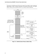
Intel Desktop Board DG965RY Technical Product Specification The amount of the system memory map. Detailed System Memory Address Map 42 Figure 14 shows a schematic of installed memory that can be used when there is no overlap of system addresses. 8 GB Top of System Address Space FLASH APIC Reserved Upper 4 GB of address ...
Intel Desktop Board DG965RY Technical Product Specification The amount of the system memory map. Detailed System Memory Address Map 42 Figure 14 shows a schematic of installed memory that can be used when there is no overlap of system addresses. 8 GB Top of System Address Space FLASH APIC Reserved Upper 4 GB of address ...

Product Specification
Page 43
... bits 7 16 bits Size 8191 MB 64 KB 64 KB 96 KB 160 KB 1 KB 127 KB 512 KB Description Extended memory Runtime BIOS Reserved Potential available high DOS memory (open to the PCI bus). Dependent on video adapter used. DFFFF 640 K - 800 K 639 K - 640 K 512...0 K - 512 K A0000 - C7FFF 9FC00 - 9FFFF 80000 - 9FBFF 00000 - 7FFFF 2.2 DMA Channels Table 11. Video memory and BIOS Extended BIOS data (movable by memory manager software) Extended conventional memory Conventional memory System Resource Open Parallel port Diskette drive Parallel port (for ECP or EPP) DMA controller Open Open Open 43...
... bits 7 16 bits Size 8191 MB 64 KB 64 KB 96 KB 160 KB 1 KB 127 KB 512 KB Description Extended memory Runtime BIOS Reserved Potential available high DOS memory (open to the PCI bus). Dependent on video adapter used. DFFFF 640 K - 800 K 639 K - 640 K 512...0 K - 512 K A0000 - C7FFF 9FC00 - 9FFFF 80000 - 9FBFF 00000 - 7FFFF 2.2 DMA Channels Table 11. Video memory and BIOS Extended BIOS data (movable by memory manager software) Extended conventional memory Conventional memory System Resource Open Parallel port Diskette drive Parallel port (for ECP or EPP) DMA controller Open Open Open 43...

Product Specification
Page 45
... Space Map Table 13. Bus number is installed. 2. PCI Configuration Space Map Bus Device Function Number (hex) Number (hex) Number (hex) Description 00 00 00 Memory controller of Intel 82G965 component 00 01 00 PCI Express x16 graphics port (Note 1) 00 02 00 Integrated graphics controller 00 1B 00... Intel High Definition Audio Controller 00 1C 00 PCI Express port 1 00 1C 01 PCI Express port 2 00 1C 02 PCI Express port 3 00 1C 03 ...
... Space Map Table 13. Bus number is installed. 2. PCI Configuration Space Map Bus Device Function Number (hex) Number (hex) Number (hex) Description 00 00 00 Memory controller of Intel 82G965 component 00 01 00 PCI Express x16 graphics port (Note 1) 00 02 00 Integrated graphics controller 00 1B 00... Intel High Definition Audio Controller 00 1C 00 PCI Express port 1 00 1C 01 PCI Express port 2 00 1C 02 PCI Express port 3 00 1C 03 ...

Product Specification
Page 61
... similar to a heavy gaming environment with no applications running and no USB current draw. These calculations are not based on specific processor values or memory configurations but are based on the system's usage model and not necessarily tied to an environment with a 500 mA current draw per USB port.... load placed on the board that will halt fan operation. Table 32. Use the datasheets for add-in cards, such as PCI, to the processor, memory, and USB ports. Maximum values assume a load placed on the board that is based on a DC analysis of a power supply at : +12 V2 (CPU) +5 ...
... similar to a heavy gaming environment with no applications running and no USB current draw. These calculations are not based on specific processor values or memory configurations but are based on the system's usage model and not necessarily tied to an environment with a 500 mA current draw per USB port.... load placed on the board that will halt fan operation. Table 32. Use the datasheets for add-in cards, such as PCI, to the processor, memory, and USB ports. Maximum values assume a load placed on the board that is based on a DC analysis of a power supply at : +12 V2 (CPU) +5 ...

Product Specification
Page 67
...and Play support. The BIOS displays a message during POST identifying the type of BIOS Features What This Chapter Contains 3.1 Introduction 67 3.2 BIOS Flash Memory Organization 68 3.3 Resource Configuration 68 3.4 System Management BIOS (SMBIOS 69 3.5 Legacy USB Support 70 3.6 BIOS Updates 70 3.7 BIOS Recovery 71 ... 73 3.10 BIOS Security Features 74 3.1 Introduction The board uses an Intel BIOS that is powered-up, the BIOS compares the CPU version and the microcode version in the Serial Peripheral Interface Flash Memory (SPI Flash) and can be updated using a disk-based program....
...and Play support. The BIOS displays a message during POST identifying the type of BIOS Features What This Chapter Contains 3.1 Introduction 67 3.2 BIOS Flash Memory Organization 68 3.3 Resource Configuration 68 3.4 System Management BIOS (SMBIOS 69 3.5 Legacy USB Support 70 3.6 BIOS Updates 70 3.7 BIOS Recovery 71 ... 73 3.10 BIOS Security Features 74 3.1 Introduction The board uses an Intel BIOS that is powered-up, the BIOS compares the CPU version and the microcode version in the Serial Peripheral Interface Flash Memory (SPI Flash) and can be updated using a disk-based program....


