Product Guide
Page 7
... Supply Cables 47 21. LAN Status LEDs 18 3. Lift the Load Plate 32 8. Remove the Processor from the Protective Processor Cover 33 10. Dual Channel Memory Configuration Example 36 14. Connecting a Serial ATA Cable 40 17. Desktop Board DG45FC China RoHS Material Self Declaration Table 75 Tables 1. LAN Connector LEDs 18 vii Close the Load...
... Supply Cables 47 21. LAN Status LEDs 18 3. Lift the Load Plate 32 8. Remove the Processor from the Protective Processor Cover 33 10. Dual Channel Memory Configuration Example 36 14. Connecting a Serial ATA Cable 40 17. Desktop Board DG45FC China RoHS Material Self Declaration Table 75 Tables 1. LAN Connector LEDs 18 vii Close the Load...
Product Guide
Page 21
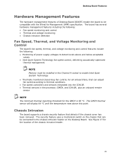
... on the Desktop Board. Desktop Board Features Hardware Management Features The hardware management features of Desktop Board DG45FC enable the board to be connected to the chassis intrusion header on the chassis that can adjust fan speed according to thermal conditions. • Fan speed controllers and sensors integrated into the ICH10R • Thermal sensors in the processor, GMCH, and...
... on the Desktop Board. Desktop Board Features Hardware Management Features The hardware management features of Desktop Board DG45FC enable the board to be connected to the chassis intrusion header on the chassis that can adjust fan speed according to thermal conditions. • Fan speed controllers and sensors integrated into the ICH10R • Thermal sensors in the processor, GMCH, and...

Product Guide
Page 47
...) power connector to the Desktop Board may result in "Before You Begin" on the Desktop Board is backwards compatible with ATX12V power supplies with 2 x 10 connectors. Observe the precautions in damage to the 2 x 2 pin connector. 47 Figure 20 shows the location of the Desktop Board power connectors. Figure 20. Connect the 12 V processor core voltage power supply cable...
...) power connector to the Desktop Board may result in "Before You Begin" on the Desktop Board is backwards compatible with ATX12V power supplies with 2 x 10 connectors. Observe the precautions in damage to the 2 x 2 pin connector. 47 Figure 20 shows the location of the Desktop Board power connectors. Figure 20. Connect the 12 V processor core voltage power supply cable...


