Product Guide
Page 6
Intel Desktop Board DG43NB Product Guide Installing and Removing a Processor 29 Installing a Processor 29 Installing a Processor Fan Heat Sink 32 Connecting the Processor Fan Heat Sink Cable 33 Removing ... Headers and Connectors 43 HD Audio Link Header 44 S/PDIF Connector 44 Chassis Intrusion Header 44 Front Panel HD Audio Header 45 USB 2.0 Headers 45 Serial Port Header 46 Front Panel Header 46 Alternate Front Panel Power LED Header 46 IEEE 1394a Header 47 Connecting to the Audio System 47 Connecting Chassis Fan...
Intel Desktop Board DG43NB Product Guide Installing and Removing a Processor 29 Installing a Processor 29 Installing a Processor Fan Heat Sink 32 Connecting the Processor Fan Heat Sink Cable 33 Removing ... Headers and Connectors 43 HD Audio Link Header 44 S/PDIF Connector 44 Chassis Intrusion Header 44 Front Panel HD Audio Header 45 USB 2.0 Headers 45 Serial Port Header 46 Front Panel Header 46 Alternate Front Panel Power LED Header 46 IEEE 1394a Header 47 Connecting to the Audio System 47 Connecting Chassis Fan...
Product Guide
Page 7
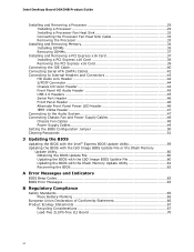
... Header Signal Names 45 9. IEEE 1394a Header Signal Names 47 vii Contents Restriction of the +5 V Standby Power Indicator 23 4. Intel Desktop Board DG43NB Components 12 3. Back Panel Audio Connectors 47 22. S/PDIF Connector Signal Names 44 7. Remove the Protective Socket Cover 30 9. Connecting the Processor Fan Heat Sink Cable 33 13. Feature ...
... Header Signal Names 45 9. IEEE 1394a Header Signal Names 47 vii Contents Restriction of the +5 V Standby Power Indicator 23 4. Intel Desktop Board DG43NB Components 12 3. Back Panel Audio Connectors 47 22. S/PDIF Connector Signal Names 44 7. Remove the Protective Socket Cover 30 9. Connecting the Processor Fan Heat Sink Cable 33 13. Feature ...
Product Guide
Page 9
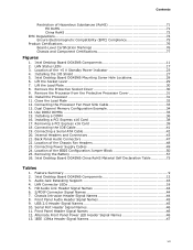
...summarizes the major features of Intel® Desktop Board DG43NB. Table 1. 1 Desktop Board Features This chapter briefly describes the features of the Desktop Board. Feature Summary Form Factor Processor Main Memory Chipset Graphics ATX (294.64 millimeters [11.60 inches] x 243.84 millimeters [9.60 inches]) Support for an Intel® processor in the ...an onboard header Peripheral Interfaces • Up to 12 USB 2.0 ports: ― Six ports routed to the back panel ― Six ports routed to three USB headers • Up to two IEEE 1394a ports: ― One port routed to the back...
...summarizes the major features of Intel® Desktop Board DG43NB. Table 1. 1 Desktop Board Features This chapter briefly describes the features of the Desktop Board. Feature Summary Form Factor Processor Main Memory Chipset Graphics ATX (294.64 millimeters [11.60 inches] x 243.84 millimeters [9.60 inches]) Support for an Intel® processor in the ...an onboard header Peripheral Interfaces • Up to 12 USB 2.0 ports: ― Six ports routed to the back panel ― Six ports routed to three USB headers • Up to two IEEE 1394a ports: ― One port routed to the back...
Product Guide
Page 10
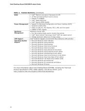
...PCI, PCI Express, PS/2, LAN, and front panel • ENERGY STAR* capable Hardware Management Hardware monitor with: • Four fan sensing inputs used to monitor fan activity • Intel® Quiet System Technology (Intel® QST) fan speed control LAN Support &#... Professional x64 Edition • Microsoft Windows XP Home For more information about Intel Desktop Board DG43NB, including the Technical Product Specification (TPS), BIOS updates, and device drivers, go to http://support.intel.com/support/motherboards/desktop/. 10 Intel Desktop Board DG43NB Product Guide Table 1.
...PCI, PCI Express, PS/2, LAN, and front panel • ENERGY STAR* capable Hardware Management Hardware monitor with: • Four fan sensing inputs used to monitor fan activity • Intel® Quiet System Technology (Intel® QST) fan speed control LAN Support &#... Professional x64 Edition • Microsoft Windows XP Home For more information about Intel Desktop Board DG43NB, including the Technical Product Specification (TPS), BIOS updates, and device drivers, go to http://support.intel.com/support/motherboards/desktop/. 10 Intel Desktop Board DG43NB Product Guide Table 1.
Product Guide
Page 14
... X4500 graphics controller supports dual independent displays via the VGA and DVI-D connectors on the Desktop Board, the Intel GMA X4500 graphics controller is installed on the Desktop Board back panel. Go to the processor, memory, PCI Express, and the DMI interconnect. Intel Desktop Board DG43NB Product Guide NOTE System resources and hardware (such as 1 GB or more information on...
... X4500 graphics controller supports dual independent displays via the VGA and DVI-D connectors on the Desktop Board, the Intel GMA X4500 graphics controller is installed on the Desktop Board back panel. Go to the processor, memory, PCI Express, and the DMI interconnect. Intel Desktop Board DG43NB Product Guide NOTE System resources and hardware (such as 1 GB or more information on...

Product Guide
Page 15
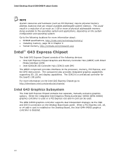
... in 5.0 Gb/s each direction simultaneously, for an aggregate of 16 GB/s when operating in 2.5 Gb/s each direction (500 MB/s total). Desktop Board Features The Intel GMA X4500 graphics controller has the following features: • Advanced graphics performance, including: ⎯ DirectX10.0* and OpenGL* 2.0 compliant ⎯ ... PCI Express x16 Graphics The GMCH supports an add-in PCI Express discrete graphics card via the DVI-D and VGA back panel connectors ⎯ High Definition Content Protection (HDCP) version 1.1 support ⎯ DDC2B compliant interface with Advanced Digital Display 2...
... in 5.0 Gb/s each direction simultaneously, for an aggregate of 16 GB/s when operating in 2.5 Gb/s each direction (500 MB/s total). Desktop Board Features The Intel GMA X4500 graphics controller has the following features: • Advanced graphics performance, including: ⎯ DirectX10.0* and OpenGL* 2.0 compliant ⎯ ... PCI Express x16 Graphics The GMCH supports an add-in PCI Express discrete graphics card via the DVI-D and VGA back panel connectors ⎯ High Definition Content Protection (HDCP) version 1.1 support ⎯ DDC2B compliant interface with Advanced Digital Display 2...
Product Guide
Page 16
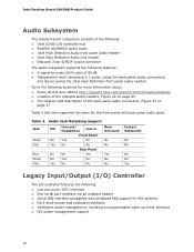
... with serialized IRQ support for the front panel and back panel audio jacks. Intel Desktop Board DG43NB Product Guide Audio Subsystem The onboard audio subsystem consists of the following: • Intel ICH10 I /O controller features the following locations for more information about: • Audio drivers and utilities http://support.intel.com/support/motherboards/desktop/ • Location of the onboard audio headers...
... with serialized IRQ support for the front panel and back panel audio jacks. Intel Desktop Board DG43NB Product Guide Audio Subsystem The onboard audio subsystem consists of the following: • Intel ICH10 I /O controller features the following locations for more information about: • Audio drivers and utilities http://support.intel.com/support/motherboards/desktop/ • Location of the onboard audio headers...
Product Guide
Page 17
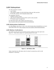
...RJ-45 LAN connector located on Intel's World Wide Web site at http://support.intel.com/support/motherboards/desktop. These LEDs indicate the operating states of the LAN. Figure 2. Desktop Board Features LAN Subsystem The LAN subsystem includes: • Intel® ICH10 • Intel 82567V Gigabit (10/100/1000 Mb... • PCI Express power management For information about LAN software and drivers go to http://support.intel.com/support/motherboards/desktop LAN Subsystem Software For LAN software and drivers, refer to the Intel Desktop Board DG43NB link on the back panel (see Figure 2).
...RJ-45 LAN connector located on Intel's World Wide Web site at http://support.intel.com/support/motherboards/desktop. These LEDs indicate the operating states of the LAN. Figure 2. Desktop Board Features LAN Subsystem The LAN subsystem includes: • Intel® ICH10 • Intel 82567V Gigabit (10/100/1000 Mb... • PCI Express power management For information about LAN software and drivers go to http://support.intel.com/support/motherboards/desktop LAN Subsystem Software For LAN software and drivers, refer to the Intel Desktop Board DG43NB link on the back panel (see Figure 2).
Product Guide
Page 18
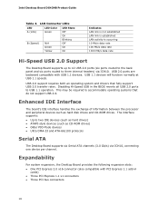
... data rate 100 Mb/s data rate 1000 Mb/s data rate Hi-Speed USB 2.0 Support The Desktop Board supports up to 12 USB 2.0 ports (six ports routed to the back panel and six ports routed to two IDE devices (such as hard drives) • ATAPI-style devices... compatible with PCI Express 1.1 add-in the BIOS reverts all USB 2.0 ports to accommodate operating systems that fully support USB 2.0 transfer rates. Intel Desktop Board DG43NB Product Guide Table 4. USB 2.0 support requires both an operating system and drivers that do not support USB 2.0. USB 1.1 devices will function normally...
... data rate 100 Mb/s data rate 1000 Mb/s data rate Hi-Speed USB 2.0 Support The Desktop Board supports up to 12 USB 2.0 ports (six ports routed to the back panel and six ports routed to two IDE devices (such as hard drives) • ATAPI-style devices... compatible with PCI Express 1.1 add-in the BIOS reverts all USB 2.0 ports to accommodate operating systems that fully support USB 2.0 transfer rates. Intel Desktop Board DG43NB Product Guide Table 4. USB 2.0 support requires both an operating system and drivers that do not support USB 2.0. USB 1.1 devices will function normally...
Product Guide
Page 22
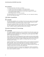
...-in cards that support this feature can damage the power supply. Intel Desktop Board DG43NB Product Guide Fan Headers The function/operation of the fans is as follows: • The fans are on the front panel, the sleep state is in memory. The Desktop Board has a 4-pin processor fan header, two 3-pin chassis fan ... be able to provide enough standby current to support multiple wake events from the PCI and/or USB buses exceeds power supply capacity, the Desktop Board may lose register settings stored in the ACPI S3, S4, or S5 state. • All fan headers support closed-loop fan control ...
...-in cards that support this feature can damage the power supply. Intel Desktop Board DG43NB Product Guide Fan Headers The function/operation of the fans is as follows: • The fans are on the front panel, the sleep state is in memory. The Desktop Board has a 4-pin processor fan header, two 3-pin chassis fan ... be able to provide enough standby current to support multiple wake events from the PCI and/or USB buses exceeds power supply capacity, the Desktop Board may lose register settings stored in the ACPI S3, S4, or S5 state. • All fan headers support closed-loop fan control ...

Product Guide
Page 25
... required for using an antistatic wrist strap and a conductive foam pad. 2 Installing and Replacing Desktop Board Components This chapter tells you how to: • Install the I/O shield • Install and remove the Desktop Board • Install and remove a processor • Install and remove memory • Install and...or modems before you can provide some ESD protection by wearing an antistatic wrist strap and attaching it to operate even though the front panel power button is not available, you begin: • Always follow the steps in each procedure in the correct order. • ...
... required for using an antistatic wrist strap and a conductive foam pad. 2 Installing and Replacing Desktop Board Components This chapter tells you how to: • Install the I/O shield • Install and remove the Desktop Board • Install and remove a processor • Install and remove memory • Install and...or modems before you can provide some ESD protection by wearing an antistatic wrist strap and attaching it to operate even though the front panel power button is not available, you begin: • Always follow the steps in each procedure in the correct order. • ...

Product Guide
Page 38
Intel Desktop Board DG43NB Product Guide Installing a PCI Express x16 Card 1. Figure 16. Observe the precautions in the connector and the card retention notch on the card snaps into place around the retention mechanism pin on page 25. 2. Secure the card's metal bracket to the chassis back panel with a screw (Figure 16, B). Place the card in the PCI Express x16 connector (Figure 16, A) and press down on the card until it is completely seated in "Before You Begin" on the connector. 3. Installing a PCI Express x16 Card 38
Intel Desktop Board DG43NB Product Guide Installing a PCI Express x16 Card 1. Figure 16. Observe the precautions in the connector and the card retention notch on the card snaps into place around the retention mechanism pin on page 25. 2. Secure the card's metal bracket to the chassis back panel with a screw (Figure 16, B). Place the card in the PCI Express x16 connector (Figure 16, A) and press down on the card until it is completely seated in "Before You Begin" on the connector. 3. Installing a PCI Express x16 Card 38

Product Guide
Page 39
This will release the card from the connector: 1. Remove the screw (Figure 17, A) that secures the card's metal bracket to remove the PCI Express x16 card from the connector (C). 4. Installing and Replacing Desktop Board Components Removing the PCI Express x16 Card Follow these instructions to the chassis back panel. 3. Removing a PCI Express x16 Card 39 Observe the precautions in the notch. Push the card ejector lever down using the tip of a pencil or similar tool (Figure 17, B) in "Before You Begin" on page 25. 2. Figure 17. Pull the card straight up.
This will release the card from the connector: 1. Remove the screw (Figure 17, A) that secures the card's metal bracket to remove the PCI Express x16 card from the connector (C). 4. Installing and Replacing Desktop Board Components Removing the PCI Express x16 Card Follow these instructions to the chassis back panel. 3. Removing a PCI Express x16 Card 39 Observe the precautions in the notch. Push the card ejector lever down using the tip of a pencil or similar tool (Figure 17, B) in "Before You Begin" on page 25. 2. Figure 17. Pull the card straight up.

Product Guide
Page 43
Item Description A HD Audio Link B S/PDIF C Chassis intrusion D Audio E USB 2.0 (3) Item Description F Serial G Front panel H Alternate front panel power LED I IEEE 1394a Figure 20. Internal Headers and Connectors 43 Installing and Replacing Desktop Board Components Connecting to Internal Headers and Connectors Before connecting cables to the internal headers and connectors, observe the precautions in "Before You Begin" on page 25. Figure 20 shows the location of the internal headers and connectors.
Item Description A HD Audio Link B S/PDIF C Chassis intrusion D Audio E USB 2.0 (3) Item Description F Serial G Front panel H Alternate front panel power LED I IEEE 1394a Figure 20. Internal Headers and Connectors 43 Installing and Replacing Desktop Board Components Connecting to Internal Headers and Connectors Before connecting cables to the internal headers and connectors, observe the precautions in "Before You Begin" on page 25. Figure 20 shows the location of the internal headers and connectors.

Product Guide
Page 45
... assignments for a full-speed USB device. 45 Turn off all peripheral devices connected to the front panel audio header, follow these steps: 1. Each USB header can be assigned as needed. Installing and Replacing Desktop Board Components Front Panel HD Audio Header Figure 20, D shows the location of the three USB 2.0 headers. Use a shielded cable...
... assignments for a full-speed USB device. 45 Turn off all peripheral devices connected to the front panel audio header, follow these steps: 1. Each USB header can be assigned as needed. Installing and Replacing Desktop Board Components Front Panel HD Audio Header Figure 20, D shows the location of the three USB 2.0 headers. Use a shielded cable...

Product Guide
Page 46
... Pin Signal Name 1 DCD 3 TXD# Pin Signal Name 2 RXD# 4 DTR 5 Ground 6 DSR 7 RTS 9 RI 8 CTS 10 No Connection Front Panel Header See Figure 20, G for the location of the serial port header. Table 11. Pins 1 and 3 of this header. If your chassis has a three...11 shows the pin assignments for the header. Table 10 shows the pin assignments for the front panel header. Table 12 shows the pin assignments for the alternate front panel header. Intel Desktop Board DG43NB Product Guide Serial Port Header See Figure 20, F for the location of the multi-colored ...
... Pin Signal Name 1 DCD 3 TXD# Pin Signal Name 2 RXD# 4 DTR 5 Ground 6 DSR 7 RTS 9 RI 8 CTS 10 No Connection Front Panel Header See Figure 20, G for the location of the serial port header. Table 11. Pins 1 and 3 of this header. If your chassis has a three...11 shows the pin assignments for the header. Table 10 shows the pin assignments for the front panel header. Table 12 shows the pin assignments for the alternate front panel header. Intel Desktop Board DG43NB Product Guide Serial Port Header See Figure 20, F for the location of the multi-colored ...
Product Guide
Page 47
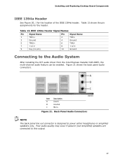
...audio quality may occur if passive (non-amplified) speakers are connected to power either headphones or amplified speakers only. Back Panel Audio Connectors NOTE The back panel line out connector is designed to this output. 47 IEEE 1394a Header Signal Names Pin Signal Name 1 TPA1+ 3 ...8 +12 V 10 Ground Connecting to the Audio System After installing the IDT audio driver from the Intel Express Installer DVD-ROM, the multi-channel audio feature can be enabled. Table 13. Installing and Replacing Desktop Board Components IEEE 1394a Header See Figure 20, I for the header.
...audio quality may occur if passive (non-amplified) speakers are connected to power either headphones or amplified speakers only. Back Panel Audio Connectors NOTE The back panel line out connector is designed to this output. 47 IEEE 1394a Header Signal Names Pin Signal Name 1 TPA1+ 3 ...8 +12 V 10 Ground Connecting to the Audio System After installing the IDT audio driver from the Intel Express Installer DVD-ROM, the multi-channel audio feature can be enabled. Table 13. Installing and Replacing Desktop Board Components IEEE 1394a Header See Figure 20, I for the header.


