Product Guide
Page 5
Contents 1 Desktop Board Features Supported Operating Systems 10 Desktop Board Components 11 Processor ...13 Main Memory...13 Intel® G41 Express Chipset 14 Intel® G41 Graphics Subsystem 15 Intel® GMA X4500 Graphics Controller (Intel® GMA X4500... 15 Audio Subsystem 16 Legacy Input/Output (I/O) Controller 17 LAN Subsystem 17 RJ-45 LAN Connector LEDs 17 Hi-Speed USB 2.0 Support 18 Enhanced IDE Interface 18 Serial ATA...18 Expandability...19 BIOS ...19 Serial ATA and IDE Auto Configuration 19 PCI* and PCI...
Contents 1 Desktop Board Features Supported Operating Systems 10 Desktop Board Components 11 Processor ...13 Main Memory...13 Intel® G41 Express Chipset 14 Intel® G41 Graphics Subsystem 15 Intel® GMA X4500 Graphics Controller (Intel® GMA X4500... 15 Audio Subsystem 16 Legacy Input/Output (I/O) Controller 17 LAN Subsystem 17 RJ-45 LAN Connector LEDs 17 Hi-Speed USB 2.0 Support 18 Enhanced IDE Interface 18 Serial ATA...18 Expandability...19 BIOS ...19 Serial ATA and IDE Auto Configuration 19 PCI* and PCI...
Product Guide
Page 6
Intel Desktop Board DG41TY Product Guide Installing a Processor 31 Installing the Processor Fan Heat Sink 34 Connecting the Processor Fan Heat Sink Cable 35 Removing the Processor 36 Installing and Removing Memory 36 Installing DIMMs 37 Removing DIMMs 39 Installing and Removing a PCI Express x16 Card 39 Installing a PCI Express x16 Card 40 Removing the PCI... 67 European Union Declaration of Conformity Statement 68 Product Ecology Statements 69 Recycling Considerations 69 Lead-Free Desktop Board 71 EMC Regulations 73 Ensure Electromagnetic Compatibility (EMC) Compliance 74 vi
Intel Desktop Board DG41TY Product Guide Installing a Processor 31 Installing the Processor Fan Heat Sink 34 Connecting the Processor Fan Heat Sink Cable 35 Removing the Processor 36 Installing and Removing Memory 36 Installing DIMMs 37 Removing DIMMs 39 Installing and Removing a PCI Express x16 Card 39 Installing a PCI Express x16 Card 40 Removing the PCI... 67 European Union Declaration of Conformity Statement 68 Product Ecology Statements 69 Recycling Considerations 69 Lead-Free Desktop Board 71 EMC Regulations 73 Ensure Electromagnetic Compatibility (EMC) Compliance 74 vi
Product Guide
Page 7
...DIMMs 37 15. Removing a PCI Express x16 Card 41 18. Connecting the IDE Cable 43 20. Location of the Standby Power Indicator 23 4. LAN Connector LEDs 18 5. Safety Standards 67 vii Location of the Chassis Fan Headers 51 24. Intel Desktop Board DG41TY Mounting Screw Hole Locations 30... Power LED Header 49 14. Lift the Socket Lever 31 7. Lift the Load Plate 32 8. Installing a DIMM 38 16. Intel Desktop Board DG41TY Components 12 3. Dual Channel Memory Configuration Example 36 14. Location of the BIOS Configuration Jumper Block 53 26. Jumper Settings for AC...
...DIMMs 37 15. Removing a PCI Express x16 Card 41 18. Connecting the IDE Cable 43 20. Location of the Standby Power Indicator 23 4. LAN Connector LEDs 18 5. Safety Standards 67 vii Location of the Chassis Fan Headers 51 24. Intel Desktop Board DG41TY Mounting Screw Hole Locations 30... Power LED Header 49 14. Lift the Socket Lever 31 7. Lift the Load Plate 32 8. Installing a DIMM 38 16. Intel Desktop Board DG41TY Components 12 3. Dual Channel Memory Configuration Example 36 14. Location of the BIOS Configuration Jumper Block 53 26. Jumper Settings for AC...
Product Guide
Page 9
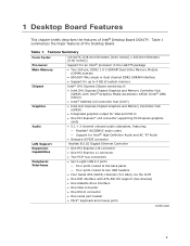
... connector • One PCI Express x1 connector • Two PCI* bus connectors • Up to eight USB 2.0 ports ― Four ports routed to the back panel ― Four ports routed to 4 GB of system memory Intel® G41 Express Chipset consisting of the Desktop Board. Table 1. 1 Desktop Board Features This chapter briefly describes the features of Intel® Desktop Board DG41TY.
... connector • One PCI Express x1 connector • Two PCI* bus connectors • Up to eight USB 2.0 ports ― Four ports routed to the back panel ― Four ports routed to 4 GB of system memory Intel® G41 Express Chipset consisting of the Desktop Board. Table 1. 1 Desktop Board Features This chapter briefly describes the features of Intel® Desktop Board DG41TY.
Product Guide
Page 10
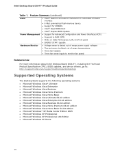
... Support for SMBIOS • Intel® Rapid BIOS Boot • Intel® Express BIOS Update Power Management • Support for Advanced Configuration and Power Interface (ACPI) • Suspend to RAM (STR) • Wake on USB, PCI Express, LAN, and front...fan speed Related Links: For more information about Intel Desktop Board DG41TY, including the Technical Product Specification (TPS), BIOS updates, and device drivers, go to: http://support.intel.com/support/motherboards/desktop/ Supported Operating Systems The Desktop Board supports the following operating systems: • Microsoft...
... Support for SMBIOS • Intel® Rapid BIOS Boot • Intel® Express BIOS Update Power Management • Support for Advanced Configuration and Power Interface (ACPI) • Suspend to RAM (STR) • Wake on USB, PCI Express, LAN, and front...fan speed Related Links: For more information about Intel Desktop Board DG41TY, including the Technical Product Specification (TPS), BIOS updates, and device drivers, go to: http://support.intel.com/support/motherboards/desktop/ Supported Operating Systems The Desktop Board supports the following operating systems: • Microsoft...
Product Guide
Page 14
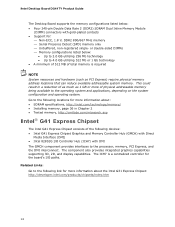
... and hardware (such as 1 GB or more information about the Intel G31 Express Chipset: http://developer.intel.com/products/chipsets/index.htm 14 Intel Desktop Board DG41TY Product Guide The Desktop Board supports the memory configurations listed below : • Up to 2.0... GB utilizing 256 Mb technology • Up to 4.0 GB utilizing 512 Mb or 1 Gb technology • A minimum of 512 MB of physical addressable memory being available to the processor, memory, PCI...
... and hardware (such as 1 GB or more information about the Intel G31 Express Chipset: http://developer.intel.com/products/chipsets/index.htm 14 Intel Desktop Board DG41TY Product Guide The Desktop Board supports the memory configurations listed below : • Up to 2.0... GB utilizing 256 Mb technology • Up to 4.0 GB utilizing 512 Mb or 1 Gb technology • A minimum of 512 MB of physical addressable memory being available to the processor, memory, PCI...
Product Guide
Page 15
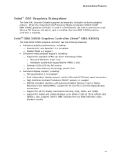
... x16 add-in card is installed, the Intel GMA X4500 graphics controller is used or a PCI Express x16 add-in and DVI digital display connections ⎯ Support for all HD display resolutions including 720p, 1080i, and 1080p ⎯ ...Software DVD at 75 Hz refresh rate (QXGA); Either the integrated Intel® Graphics Media Accelerator X4500 (Intel® GMA X4500) graphics controller is disabled. support for TV-out/TV-in card can be used. Desktop Board Features Intel® G41 Graphics Subsystem The Intel G41 Express Chipset supports two separate, mutually exclusive graphics options.
... x16 add-in card is installed, the Intel GMA X4500 graphics controller is used or a PCI Express x16 add-in and DVI digital display connections ⎯ Support for all HD display resolutions including 720p, 1080i, and 1080p ⎯ ...Software DVD at 75 Hz refresh rate (QXGA); Either the integrated Intel® Graphics Media Accelerator X4500 (Intel® GMA X4500) graphics controller is disabled. support for TV-out/TV-in card can be used. Desktop Board Features Intel® G41 Graphics Subsystem The Intel G41 Express Chipset supports two separate, mutually exclusive graphics options.
Product Guide
Page 17
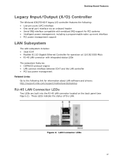
... LAN. Desktop Board Features Legacy Input/Output (I/O) Controller The Winbond 83627DHG-P legacy I/O controller features the following: • Low pin count (LPC) interface • One serial port interface via an onboard header • Serial IRQ interface compatible with serialized IRQ support for PCI systems &#...LAN connect interface between ICH7 and the LAN controller • PCI bus power management Related Links: Go to the following link for information about LAN software and drivers: http://support.intel.com/support/motherboards/desktop RJ-45 LAN Connector LEDs Two LEDs are built into ...
... LAN. Desktop Board Features Legacy Input/Output (I/O) Controller The Winbond 83627DHG-P legacy I/O controller features the following: • Low pin count (LPC) interface • One serial port interface via an onboard header • Serial IRQ interface compatible with serialized IRQ support for PCI systems &#...LAN connect interface between ICH7 and the LAN controller • PCI bus power management Related Links: Go to the following link for information about LAN software and drivers: http://support.intel.com/support/motherboards/desktop RJ-45 LAN Connector LEDs Two LEDs are built into ...
Product Guide
Page 19
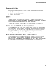
... Self-Test (POST), the BIOS Setup program, the PCI/PCI Express and IDE auto-configuration utilities, and the video BIOS. The BIOS is stored in card. 19 Desktop Board Features Expandability For system expansion, the Desktop Board provides the following the instructions on page 61 in Chapter... 3. Serial ATA and IDE Auto Configuration If you install a PCI/PCI Express add-in the Serial Peripheral Interface (SPI) ...
... Self-Test (POST), the BIOS Setup program, the PCI/PCI Express and IDE auto-configuration utilities, and the video BIOS. The BIOS is stored in card. 19 Desktop Board Features Expandability For system expansion, the Desktop Board provides the following the instructions on page 61 in Chapter... 3. Serial ATA and IDE Auto Configuration If you install a PCI/PCI Express add-in the Serial Peripheral Interface (SPI) ...
Product Guide
Page 23
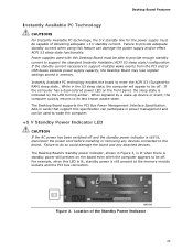
...delivering adequate +5 V standby current. If the standby current necessary to support multiple wake events from the PCI and/or USB buses exceeds power supply capacity, the Desktop Board may lose register settings stored in power management and can be used with this feature can participate in ...memory. While in Figure 3, is lit when there is still present at the memory module sockets and the PCI bus connectors. Figure 3. Desktop Board Features Instantly Available PC Technology CAUTIONS For Instantly Available PC technology, the 5 V standby line for the power supply must...
...delivering adequate +5 V standby current. If the standby current necessary to support multiple wake events from the PCI and/or USB buses exceeds power supply capacity, the Desktop Board may lose register settings stored in power management and can be used with this feature can participate in ...memory. While in Figure 3, is lit when there is still present at the memory module sockets and the PCI bus connectors. Figure 3. Desktop Board Features Instantly Available PC Technology CAUTIONS For Instantly Available PC technology, the 5 V standby line for the power supply must...
Product Guide
Page 24
...Desktop Board, refer to the Technical Product Specification by going to http://www.intel.com/go to the following link, finding the product, and selecting Product Documentation from the left-hand menu: http://support.intel.com/support/motherboards/desktop...during the Power-On Self-Test (POST). Battery A battery on the Desktop Board. Intel Desktop Board DG41TY Product Guide Related Links: For more information concerning ENERGY STAR, go /...PCI Express bus is turned off. ENERGY STAR* Capable In 2007, the US Department of a USB peripheral that supports Wake from USB. This Desktop Board...
...Desktop Board, refer to the Technical Product Specification by going to http://www.intel.com/go to the following link, finding the product, and selecting Product Documentation from the left-hand menu: http://support.intel.com/support/motherboards/desktop...during the Power-On Self-Test (POST). Battery A battery on the Desktop Board. Intel Desktop Board DG41TY Product Guide Related Links: For more information concerning ENERGY STAR, go /...PCI Express bus is turned off. ENERGY STAR* Capable In 2007, the US Department of a USB peripheral that supports Wake from USB. This Desktop Board...
Product Guide
Page 27
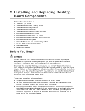
...or modems before you how to: • Install the I/O shield • Install and remove the Desktop Board • Install and remove a processor • Install and remove memory • Install and remove a PCI Express x16 card • Connect the diskette drive cable • Connect the IDE and Serial ATA ...using an antistatic wrist strap and a conductive foam pad. Perform the procedures described in this chapter. 2 Installing and Replacing Desktop Board Components This chapter tells you open the computer or perform any procedures can result in personal injury or equipment damage.
...or modems before you how to: • Install the I/O shield • Install and remove the Desktop Board • Install and remove a processor • Install and remove memory • Install and remove a PCI Express x16 card • Connect the diskette drive cable • Connect the IDE and Serial ATA ...using an antistatic wrist strap and a conductive foam pad. Perform the procedures described in this chapter. 2 Installing and Replacing Desktop Board Components This chapter tells you open the computer or perform any procedures can result in personal injury or equipment damage.
Product Guide
Page 39
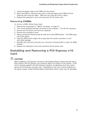
... and reconnect the AC power cord. Insert the bottom edge of the DIMM into place. Depending on the Desktop Board, ensure that the card is not fully seated in the PCI Express x16 connector before you removed or disconnected to the computer. When the DIMM is inserted, push down ...on the system. Reinstall and reconnect any parts you power on the top edge of the power supply, certain Desktop Board components and/or traces may result across the PCI Express connector pins. Remove the computer's cover. 5. Gently spread the retaining clips at each end of the socket. 6....
... and reconnect the AC power cord. Insert the bottom edge of the DIMM into place. Depending on the Desktop Board, ensure that the card is not fully seated in the PCI Express x16 connector before you removed or disconnected to the computer. When the DIMM is inserted, push down ...on the system. Reinstall and reconnect any parts you power on the top edge of the power supply, certain Desktop Board components and/or traces may result across the PCI Express connector pins. Remove the computer's cover. 5. Gently spread the retaining clips at each end of the socket. 6....
Product Guide
Page 40
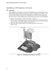
...chassis back panel with a screw (Figure 16, B). Depending on the over-current protection of the power supply, certain desktop board components and/or traces may result across the PCI Express connector pins. If the card is not fully seated in "Before You Begin" on page 27. 2. Place ...on the card until it is completely seated in the PCI Express x16 connector before you power on the system. Figure 16. Intel Desktop Board DG41TY Product Guide Installing a PCI Express x16 Card CAUTION When installing a PCI Express x16 card on the desktop board, ensure that the card is fully seated in the ...
...chassis back panel with a screw (Figure 16, B). Depending on the over-current protection of the power supply, certain desktop board components and/or traces may result across the PCI Express connector pins. If the card is not fully seated in "Before You Begin" on page 27. 2. Place ...on the card until it is completely seated in the PCI Express x16 connector before you power on the system. Figure 16. Intel Desktop Board DG41TY Product Guide Installing a PCI Express x16 Card CAUTION When installing a PCI Express x16 card on the desktop board, ensure that the card is fully seated in the ...

Product Guide
Page 41
Pull the card straight up. Push the card ejector lever down using the tip of a pencil or similar tool in "Before You Begin" on page 27. 2. Removing a PCI Express x16 Card 41 Remove the screw (Figure 17, A) that secures the card's metal bracket to remove the PCI Express x16 card from the connector (Figure 17, C). 4. This will release the card from the connector: 1. Figure 17. Installing and Replacing Desktop Board Components Removing the PCI Express x16 Card Follow these instructions to the chassis back panel. 3. Observe the precautions in the notch (Figure 17, B).
Pull the card straight up. Push the card ejector lever down using the tip of a pencil or similar tool in "Before You Begin" on page 27. 2. Removing a PCI Express x16 Card 41 Remove the screw (Figure 17, A) that secures the card's metal bracket to remove the PCI Express x16 card from the connector (Figure 17, C). 4. This will release the card from the connector: 1. Figure 17. Installing and Replacing Desktop Board Components Removing the PCI Express x16 Card Follow these instructions to the chassis back panel. 3. Observe the precautions in the notch (Figure 17, B).

