Product Guide
Page 5
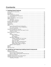
Contents 1 Desktop Board Features Desktop Board Components 11 Processor ...13 Main Memory...13 Intel® G35 Express Chipset 14 Intel G35 Graphics Subsystem 14 Audio Subsystem 15 Legacy Input/Output (I/O) Controller 16 LAN Subsystem 16 LAN ... ...23 Real-Time Clock 23 2 Installing and Replacing Desktop Board Components Before You Begin 25 Installation Precautions 26 Prevent Power Supply Overload 26 Observe Safety and Regulatory Requirements 26 Installing the I/O Shield 27 Installing and Removing the Desktop Board 28 Installing and Removing a Processor 29 Installing a Processor...
Contents 1 Desktop Board Features Desktop Board Components 11 Processor ...13 Main Memory...13 Intel® G35 Express Chipset 14 Intel G35 Graphics Subsystem 14 Audio Subsystem 15 Legacy Input/Output (I/O) Controller 16 LAN Subsystem 16 LAN ... ...23 Real-Time Clock 23 2 Installing and Replacing Desktop Board Components Before You Begin 25 Installation Precautions 26 Prevent Power Supply Overload 26 Observe Safety and Regulatory Requirements 26 Installing the I/O Shield 27 Installing and Removing the Desktop Board 28 Installing and Removing a Processor 29 Installing a Processor...

Product Guide
Page 7
... Processor from the Protective Processor Cover 31 10. Internal Headers 44 24. Connecting Power Supply Cables 50 27. Desktop Board DG35EC China RoHS Material Self Declaration Table 73 vii Lift the Load Plate 30 8. Installing the I/O Shield 27 5. Connecting a Serial ATA Cable 43 23. Contents EU RoHS 71 China RoHS 72 EMC Regulations 74...
... Processor from the Protective Processor Cover 31 10. Internal Headers 44 24. Connecting Power Supply Cables 50 27. Desktop Board DG35EC China RoHS Material Self Declaration Table 73 vii Lift the Load Plate 30 8. Installing the I/O Shield 27 5. Connecting a Serial ATA Cable 43 23. Contents EU RoHS 71 China RoHS 72 EMC Regulations 74...
Product Guide
Page 25
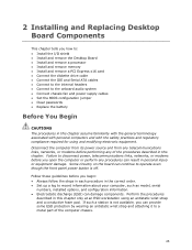
... links, networks, or modems before performing any procedures can result in personal injury or equipment damage. Some circuitry on the board can continue to operate even though the front panel power button is not available, you can provide some ESD protection by ... you open the computer or perform any of the computer chassis. 25 2 Installing and Replacing Desktop Board Components This chapter tells you how to: • Install the I/O shield • Install and remove the Desktop Board • Install and remove a processor • Install and remove memory • Install and...
... links, networks, or modems before performing any procedures can result in personal injury or equipment damage. Some circuitry on the board can continue to operate even though the front panel power button is not available, you can provide some ESD protection by ... you open the computer or perform any of the computer chassis. 25 2 Installing and Replacing Desktop Board Components This chapter tells you how to: • Install the I/O shield • Install and remove the Desktop Board • Install and remove a processor • Install and remove memory • Install and...

Product Guide
Page 27
... frequency transmissions, protects internal components from the chassis supplier. Figure 4. Installing the I /O shield before installing the Desktop Board in the chassis. Press the shield into place so that it fits tightly and securely. If the shield does not fit, obtain a properly sized shield from dust and foreign objects, and promotes correct airflow within the chassis. When...
... frequency transmissions, protects internal components from the chassis supplier. Figure 4. Installing the I /O shield before installing the Desktop Board in the chassis. Press the shield into place so that it fits tightly and securely. If the shield does not fit, obtain a properly sized shield from dust and foreign objects, and promotes correct airflow within the chassis. When...
Product Guide
Page 45
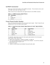
... the S/PDIF connector. Turn off the computer and disconnect the AC power cord. 3. Remove the cover. 4. Front Panel Audio Header Signal Names for Intel® High Definition Audio Pin Signal Name 1 PORT 1L 3 PORT 1R 5 PORT 2R 7 SENSE_SEND 9 PORT 2L Pin Signal Name 2 GND 4...install the cable that connects the front panel audio solution to the computer. Install a correctly keyed and shielded front panel audio cable. 45 Installing and Replacing Desktop Board Components S/PDIF Connector Figure 23, A shows the location of the front panel audio header. This connector...
... the S/PDIF connector. Turn off the computer and disconnect the AC power cord. 3. Remove the cover. 4. Front Panel Audio Header Signal Names for Intel® High Definition Audio Pin Signal Name 1 PORT 1L 3 PORT 1R 5 PORT 2R 7 SENSE_SEND 9 PORT 2L Pin Signal Name 2 GND 4...install the cable that connects the front panel audio solution to the computer. Install a correctly keyed and shielded front panel audio cable. 45 Installing and Replacing Desktop Board Components S/PDIF Connector Figure 23, A shows the location of the front panel audio header. This connector...

Product Guide
Page 47
...+ Ground No Connection NOTE Computer systems that meets the requirements for the location of the alternate front panel power LED header. Installing and Replacing Desktop Board Components Alternate Front Panel Power LED Header Figure 23, F shows the location of the three USB 2.0 headers. Table 10 shows the pin... front panel header. Each USB header can be assigned as needed. Table 9 shows the pin assignments for each USB 2.0 header. Use a shielded cable that have an unshielded cable attached to a USB port might not meet FCC Class B requirements, even if no device or a low-...
...+ Ground No Connection NOTE Computer systems that meets the requirements for the location of the alternate front panel power LED header. Installing and Replacing Desktop Board Components Alternate Front Panel Power LED Header Figure 23, F shows the location of the three USB 2.0 headers. Table 10 shows the pin... front panel header. Each USB header can be assigned as needed. Table 9 shows the pin assignments for each USB 2.0 header. Use a shielded cable that have an unshielded cable attached to a USB port might not meet FCC Class B requirements, even if no device or a low-...

Product Guide
Page 75
... before integration, then EMC testing may use this equipment in residential environments and other modules: • Product certifications or lack of certifications • External I/O cable shielding and filtering • Mounting, grounding, and bonding requirements • Keying connectors when mating the wrong connectors could be required on a representative sample of the newly...
... before integration, then EMC testing may use this equipment in residential environments and other modules: • Product certifications or lack of certifications • External I/O cable shielding and filtering • Mounting, grounding, and bonding requirements • Keying connectors when mating the wrong connectors could be required on a representative sample of the newly...

Product Specification
Page 40
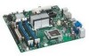
... and internal peripherals. NOTE Computer systems that meets the requirements for full-speed devices. Use shielded cable that have overcurrent protection: Back panel and front panel USB, PS/2, and VGA. This section describes the board's connectors and headers. Intel Desktop Board DG35EC Technical Product Specification 2.2 Connectors and Headers CAUTION Only the following connectors and headers have...
... and internal peripherals. NOTE Computer systems that meets the requirements for full-speed devices. Use shielded cable that have overcurrent protection: Back panel and front panel USB, PS/2, and VGA. This section describes the board's connectors and headers. Intel Desktop Board DG35EC Technical Product Specification 2.2 Connectors and Headers CAUTION Only the following connectors and headers have...