Product Guide
Page 5
Contents 1 Desktop Board Features Desktop Board Components 11 Processor ...13 Main Memory...13 Intel® G35 Express Chipset 14 Intel G35 Graphics Subsystem 14 Audio Subsystem 15 Legacy Input/Output (I/O) Controller 16 LAN Subsystem 16 LAN Status Indicators 16 Hi-Speed USB 2.0 Support 17 Enhanced IDE Interface 17 Serial ATA...17 Expandability...18 BIOS ...18 Serial ATA and IDE...
Contents 1 Desktop Board Features Desktop Board Components 11 Processor ...13 Main Memory...13 Intel® G35 Express Chipset 14 Intel G35 Graphics Subsystem 14 Audio Subsystem 15 Legacy Input/Output (I/O) Controller 16 LAN Subsystem 16 LAN Status Indicators 16 Hi-Speed USB 2.0 Support 17 Enhanced IDE Interface 17 Serial ATA...17 Expandability...18 BIOS ...18 Serial ATA and IDE...
Product Guide
Page 9
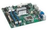
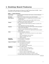
... Graphics and Memory Controller Hub (GMCH) • Intel® 82801HB I/O Controller Hub (ICH8) • Intel G35 Express Chipset with Intel® Graphics Media Accelerator X3500 (Intel® GMA X3500) • Support for up to 8 GB of system memory Intel® G35 Express Chipset consisting of the Desktop Board. Table 1. 1 Desktop Board Features This chapter briefly describes the features of Intel® Desktop Board DG35EC.
... Graphics and Memory Controller Hub (GMCH) • Intel® 82801HB I/O Controller Hub (ICH8) • Intel G35 Express Chipset with Intel® Graphics Media Accelerator X3500 (Intel® GMA X3500) • Support for up to 8 GB of system memory Intel® G35 Express Chipset consisting of the Desktop Board. Table 1. 1 Desktop Board Features This chapter briefly describes the features of Intel® Desktop Board DG35EC.
Product Guide
Page 12
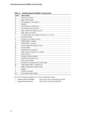
... High-speed USB 2.0 headers (2) BIOS configuration jumper block Battery S/PDIF connector Front panel audio header Go to the following locations for more information about: • Desktop Board DG35EC • Supported processors http://www.intel.com/design/motherbd http://www.intel.com/go/findCPU 12
... High-speed USB 2.0 headers (2) BIOS configuration jumper block Battery S/PDIF connector Front panel audio header Go to the following locations for more information about: • Desktop Board DG35EC • Supported processors http://www.intel.com/design/motherbd http://www.intel.com/go/findCPU 12
Product Guide
Page 13
... at power up. Go to 8.0 GB utilizing 1 Gb technology 13 Desktop Board DG35EC supports an Intel processor in damage to this effect on installing or upgrading the processor, page 29 in Chapter 2 • Supported processors for normal operation. The processor connects to configure the memory controller for Desktop Board DG35EC, http://www.intel.com/go/findCPU Main Memory NOTE To be fully compliant with...
... at power up. Go to 8.0 GB utilizing 1 Gb technology 13 Desktop Board DG35EC supports an Intel processor in damage to this effect on installing or upgrading the processor, page 29 in Chapter 2 • Supported processors for normal operation. The processor connects to configure the memory controller for Desktop Board DG35EC, http://www.intel.com/go/findCPU Main Memory NOTE To be fully compliant with...

Product Guide
Page 14
...supporting 3D, 2D, and display capabilities. When a PCI Express x16 add-in card is installed on the Desktop Board, the Intel GMA X3500 graphics controller is used or a PCI Express x16 add-in Chapter 2 • Tested memory, http://www.cmtlabs.com/mbsearch.asp or http://www.intel.com/products/motherboard... integrated Intel Graphics Media Accelerator X3500 (GMA X3500) graphics controller is disabled. 14 The ICH8 is a centralized controller for more information on the Desktop Board back panel. Intel Desktop Board DG35EC Product Guide Go to the following devices: • Intel G35 Express...
...supporting 3D, 2D, and display capabilities. When a PCI Express x16 add-in card is installed on the Desktop Board, the Intel GMA X3500 graphics controller is used or a PCI Express x16 add-in Chapter 2 • Tested memory, http://www.cmtlabs.com/mbsearch.asp or http://www.intel.com/products/motherboard... integrated Intel Graphics Media Accelerator X3500 (GMA X3500) graphics controller is disabled. 14 The ICH8 is a centralized controller for more information on the Desktop Board back panel. Intel Desktop Board DG35EC Product Guide Go to the following devices: • Intel G35 Express...
Product Guide
Page 17
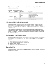
... interface handles the exchange of information between the processor and peripheral devices such as CD-ROM drives) • Older PIO Mode devices • Ultra DMA-33 and ATA-66/100 protocols Serial ATA The Desktop Board supports four Serial ATA channels (3.0 Gb/s) via ICH8. USB 1.1 devices will... Mb/s data rate 1000 Mb/s data rate Hi-Speed USB 2.0 Support The Desktop Board supports up to 10 USB 2.0 ports (six ports routed to the back panel and four ports routed to accommodate operating systems that fully support USB 2.0 transfer rates. USB 2.0 ports are backward compatible with USB...
... interface handles the exchange of information between the processor and peripheral devices such as CD-ROM drives) • Older PIO Mode devices • Ultra DMA-33 and ATA-66/100 protocols Serial ATA The Desktop Board supports four Serial ATA channels (3.0 Gb/s) via ICH8. USB 1.1 devices will... Mb/s data rate 1000 Mb/s data rate Hi-Speed USB 2.0 Support The Desktop Board supports up to 10 USB 2.0 ports (six ports routed to the back panel and four ports routed to accommodate operating systems that fully support USB 2.0 transfer rates. USB 2.0 ports are backward compatible with USB...
Product Guide
Page 19
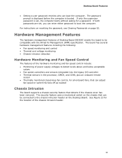
...and below acceptable values • Fan speed controllers and sensors integrated into the legacy I/O controller • Thermal sensors in the processor, GMCH, and ICH8, plus an onboard remote sensor • Thermally monitored closed-loop fan control, for all onboard fans, ... as needed Chassis Intrusion The board supports a chassis security feature that can boot the computer. For instructions on resetting the password, see Clearing Passwords on the Desktop Board. Hardware Management Features The hardware management features of Desktop Board DG35EC enable the board to be connected to the ...
...and below acceptable values • Fan speed controllers and sensors integrated into the legacy I/O controller • Thermal sensors in the processor, GMCH, and ICH8, plus an onboard remote sensor • Thermally monitored closed-loop fan control, for all onboard fans, ... as needed Chassis Intrusion The board supports a chassis security feature that can boot the computer. For instructions on resetting the password, see Clearing Passwords on the Desktop Board. Hardware Management Features The hardware management features of Desktop Board DG35EC enable the board to be connected to the ...
Product Guide
Page 21
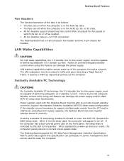
... stored in the ACPI S3, S4, or S5 state. • All fan headers support closed-loop fan control that powers up of delivering adequate +5 V standby current. The Desktop Board supports the PCI Bus Power Management Interface Specification. Failure to enter the ACPI S3 (Suspend-toRAM...8226; The fans are on the front panel, the sleep state is in memory. Desktop Board Features Fan Headers The function/operation of delivering adequate +5 V standby current. The Desktop Board has a 4-pin processor fan header and two 3-pin chassis fan headers. When signaled by the LED turning amber...
... stored in the ACPI S3, S4, or S5 state. • All fan headers support closed-loop fan control that powers up of delivering adequate +5 V standby current. The Desktop Board supports the PCI Bus Power Management Interface Specification. Failure to enter the ACPI S3 (Suspend-toRAM...8226; The fans are on the front panel, the sleep state is in memory. Desktop Board Features Fan Headers The function/operation of delivering adequate +5 V standby current. The Desktop Board has a 4-pin processor fan header and two 3-pin chassis fan headers. When signaled by the LED turning amber...

Product Guide
Page 26
Intel Desktop Board DG35EC Product Guide Installation Precautions When you to refer computer servicing to qualified technical personnel. If the instructions for associated modules, contact the supplier's technical support to Appendix B on the chassis • Hot components (such as processors, voltage regulators, and heat sinks) • Damage to wires that could cause a short circuit Observe all warnings...
Intel Desktop Board DG35EC Product Guide Installation Precautions When you to refer computer servicing to qualified technical personnel. If the instructions for associated modules, contact the supplier's technical support to Appendix B on the chassis • Hot components (such as processors, voltage regulators, and heat sinks) • Damage to wires that could cause a short circuit Observe all warnings...

Product Specification
Page 5
... Description 1.1 Overview 10 1.1.1 Feature Summary 10 1.1.2 Board Layout 12 1.1.3 Block Diagram 14 1.2 Legacy Considerations 15 1.3 Online Support 15 1.4 Processor 15 1.5 System Memory 16 1.5.1 Memory Configurations 17 1.6 Intel® G35 Express Chipset 19 1.6.1 Intel G35 Graphics Subsystem 19 1.6.2 USB 21 1.6.3 Serial ...Chassis Intrusion and Detection 28 1.12.4 Thermal Monitoring 29 1.13 Power Management 30 1.13.1 ACPI 30 1.13.2 Hardware Support 33 2 Technical Reference 2.1 Memory Map 37 2.1.1 Addressable Memory 37 2.2 Connectors and Headers 40 2.2.1 Back Panel Connectors ...
... Description 1.1 Overview 10 1.1.1 Feature Summary 10 1.1.2 Board Layout 12 1.1.3 Block Diagram 14 1.2 Legacy Considerations 15 1.3 Online Support 15 1.4 Processor 15 1.5 System Memory 16 1.5.1 Memory Configurations 17 1.6 Intel® G35 Express Chipset 19 1.6.1 Intel G35 Graphics Subsystem 19 1.6.2 USB 21 1.6.3 Serial ...Chassis Intrusion and Detection 28 1.12.4 Thermal Monitoring 29 1.13 Power Management 30 1.13.1 ACPI 30 1.13.2 Hardware Support 33 2 Technical Reference 2.1 Memory Map 37 2.1.1 Addressable Memory 37 2.2 Connectors and Headers 40 2.2.1 Back Panel Connectors ...
Product Specification
Page 7
... the Power Switch 30 7. Connection Diagram for a One-Color Power LED 48 23. Board Dimensions 51 15. Board Components Shown in Figure 10 43 11. Audio Jack Support 24 5. System Memory Map 39 10. Processor Fan Header 44 16. S/PDIF Connector 45 17. Auxiliary Front Panel Power/Sleep LED ...16 4. Effects of the Standby Power Indicator LED 36 8. Serial ATA Connectors 44 12. Front and Rear Chassis Fan Headers 44 15. Processor Core Power Connector 46 20. Thermal Sensors and Fan Headers 29 7. Localized High Temperature Zones 54 Tables 1. Wake-up Devices and Events ...
... the Power Switch 30 7. Connection Diagram for a One-Color Power LED 48 23. Board Dimensions 51 15. Board Components Shown in Figure 10 43 11. Audio Jack Support 24 5. System Memory Map 39 10. Processor Fan Header 44 16. S/PDIF Connector 45 17. Auxiliary Front Panel Power/Sleep LED ...16 4. Effects of the Standby Power Indicator LED 36 8. Serial ATA Connectors 44 12. Front and Rear Chassis Fan Headers 44 15. Processor Core Power Connector 46 20. Thermal Sensors and Fan Headers 29 7. Localized High Temperature Zones 54 Tables 1. Wake-up Devices and Events ...
Product Specification
Page 9
1 Product Description What This Chapter Contains 1.1 Overview 10 1.2 Legacy Considerations 15 1.3 Online Support 15 1.4 Processor 15 1.5 System Memory 16 1.6 Intel® G35 Express Chipset 19 1.7 Parallel IDE Controller 22 1.8 Real-Time Clock Subsystem 23 1.9 Legacy I/O Controller 23 1.10 Audio Subsystem 24 1.11 LAN Subsystem 26 1.12 Hardware Management Subsystem 28 1.13 Power Management 30 9
1 Product Description What This Chapter Contains 1.1 Overview 10 1.2 Legacy Considerations 15 1.3 Online Support 15 1.4 Processor 15 1.5 System Memory 16 1.6 Intel® G35 Express Chipset 19 1.7 Parallel IDE Controller 22 1.8 Real-Time Clock Subsystem 23 1.9 Legacy I/O Controller 23 1.10 Audio Subsystem 24 1.11 LAN Subsystem 26 1.12 Hardware Management Subsystem 28 1.13 Power Management 30 9

Product Specification
Page 10
... 1.1 • Suspend to 8 GB of system memory Intel® G35 Express Chipset, consisting of the Desktop Board DG35EC. Feature Summary Form Factor microATX (9.60 inches by 9.60 inches [243.84 millimeters by 243.84 millimeters]) Processor Memory Chipset Video Support for the following: • Intel® Core™2 Quad processor in an LGA775 socket with a 1333 MHz or...
... 1.1 • Suspend to 8 GB of system memory Intel® G35 Express Chipset, consisting of the Desktop Board DG35EC. Feature Summary Form Factor microATX (9.60 inches by 9.60 inches [243.84 millimeters by 243.84 millimeters]) Processor Memory Chipset Video Support for the following: • Intel® Core™2 Quad processor in an LGA775 socket with a 1333 MHz or...
Product Specification
Page 15
... falling within the wattage requirements of 95 W. The processors listed above . Supported processors Refer to: http://www.intel.com/go /findcpu http://www.intel.com/products/desktop/chipsets/index.htm http://downloadcenter.intel.com http://support.intel.com/support/motherboards/desktop/sb/CS025414.htm 1.4 Processor The board is designed to support processors with a maximum wattage of the DG35EC board. Intel Desktop Board DG35EC Desktop Board Support Available configurations for the most up-to-date list...
... falling within the wattage requirements of 95 W. The processors listed above . Supported processors Refer to: http://www.intel.com/go /findcpu http://www.intel.com/products/desktop/chipsets/index.htm http://downloadcenter.intel.com http://support.intel.com/support/motherboards/desktop/sb/CS025414.htm 1.4 Processor The board is designed to support processors with a maximum wattage of the DG35EC board. Intel Desktop Board DG35EC Desktop Board Support Available configurations for the most up-to-date list...

Product Specification
Page 22
Intel Desktop Board DG35EC Technical Product Specification NOTE Many Serial ATA drives use new low-voltage power connectors and require adapters or power supplies equipped with low-voltage power connectors. The Parallel ATA IDE interface supports the following modes: • Programmed I/O (PIO): processor controls data transfer. • 8237-style DMA: DMA offloads the processor, supporting transfer rates of up...
Intel Desktop Board DG35EC Technical Product Specification NOTE Many Serial ATA drives use new low-voltage power connectors and require adapters or power supplies equipped with low-voltage power connectors. The Parallel ATA IDE interface supports the following modes: • Programmed I/O (PIO): processor controls data transfer. • 8237-style DMA: DMA offloads the processor, supporting transfer rates of up...
Product Specification
Page 28
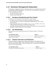
...Intel Desktop Board DG35EC Technical Product Specification 1.12 Hardware Management Subsystem The hardware management features enable the board to be implemented using Intel® Desktop... Utilities or third-party software. For information about The functions of the fan headers Location of five voltages (+5 V, +12 V, +3.3 VSB, +1.25 V, and +VCCP) to Section 1.13.2.2, page 34 Figure 6, page 29 1.12.3 Chassis Intrusion and Detection The board supports...into the ICH8 • Four thermal sensors (processor, 82G35 GMCH, 82801HB ICH8, and a ...
...Intel Desktop Board DG35EC Technical Product Specification 1.12 Hardware Management Subsystem The hardware management features enable the board to be implemented using Intel® Desktop... Utilities or third-party software. For information about The functions of the fan headers Location of five voltages (+5 V, +12 V, +3.3 VSB, +1.25 V, and +VCCP) to Section 1.13.2.2, page 34 Figure 6, page 29 1.12.3 Chassis Intrusion and Detection The board supports...into the ICH8 • Four thermal sensors (processor, 82G35 GMCH, 82801HB ICH8, and a ...
Product Specification
Page 31
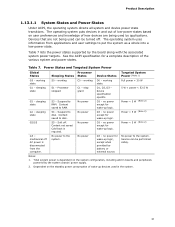
.... Total system power is dependent on user preferences and knowledge of the various system and power states. Table 7 lists the power states supported by the system chassis' power supply. 2. mechanical off . Suspend to disk. Suspend to RAM. S5 - stop grant G1 - ...for a complete description of how devices are not being used in boards and peripherals powered by the board along with the associated system power targets. Table 7. Power States and Targeted System Power Global States Processor Sleeping States States Device States Targeted System Power (Note 1) G0 ...
.... Total system power is dependent on user preferences and knowledge of the various system and power states. Table 7 lists the power states supported by the system chassis' power supply. 2. mechanical off . Suspend to disk. Suspend to RAM. S5 - stop grant G1 - ...for a complete description of how devices are not being used in boards and peripherals powered by the board along with the associated system power targets. Table 7. Power States and Targeted System Power Global States Processor Sleeping States States Device States Targeted System Power (Note 1) G0 ...
Product Specification
Page 34
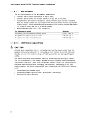
...input of the hardware monitoring and fan control device. All fan headers support closed-loop fan control that powers up the computer. LAN wake capabilities enable remote wake-up signal that can damage the power supply. Intel Desktop Board DG35EC Technical Product Specification 1.13.2.2 Fan Headers The function/operation of the ...capabilities with ACPI in the S0 state. • The fans are on or off or in the S3, S4, or S5 state. • The processor fan header is in the following ways: • The PCI Express WAKE# signal • The PCI bus PME# signal for PCI 2.3 compliant LAN...
...input of the hardware monitoring and fan control device. All fan headers support closed-loop fan control that powers up the computer. LAN wake capabilities enable remote wake-up signal that can damage the power supply. Intel Desktop Board DG35EC Technical Product Specification 1.13.2.2 Fan Headers The function/operation of the ...capabilities with ACPI in the S0 state. • The fans are on or off or in the S3, S4, or S5 state. • The processor fan header is in the following ways: • The PCI Express WAKE# signal • The PCI bus PME# signal for PCI 2.3 compliant LAN...
Product Specification
Page 46
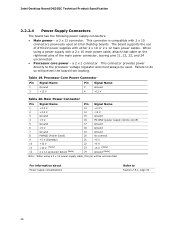
...board supports the use of ATX12V power supplies with a 2 x 10 main power cable, attach that cable on the rightmost pins of the main power connector, leaving pins 11, 12, 23, and 24 unconnected. • Processor core power - When using a 2 x 10 power supply cable, this pin will prevent the board...main power cables. Processor Core Power Connector Pin Signal Name Pin Signal Name 1 Ground 3 +12 V 2 Ground 4 +12 V Table 20. Table 19. a 2 x 12 connector. Intel Desktop Board DG35EC Technical Product Specification 2.2.2.4 Power Supply Connectors The board has the following ...
...board supports the use of ATX12V power supplies with a 2 x 10 main power cable, attach that cable on the rightmost pins of the main power connector, leaving pins 11, 12, 23, and 24 unconnected. • Processor core power - When using a 2 x 10 power supply cable, this pin will prevent the board...main power cables. Processor Core Power Connector Pin Signal Name Pin Signal Name 1 Ground 3 +12 V 2 Ground 4 +12 V Table 20. Table 19. a 2 x 12 connector. Intel Desktop Board DG35EC Technical Product Specification 2.2.2.4 Power Supply Connectors The board has the following ...

Product Specification
Page 52
Intel Desktop Board DG35EC Technical Product Specification 2.5 Electrical Considerations...for a system consisting of a supported 65 W processor (see Section 1.4 on page 15 for a list of supported processors), 1 GB DDR2 RAM, one hard disk drive, one optical drive, and all board peripherals enabled, the minimum recommended ... +5 V standby current. Additional power required will depend on the wake devices supported and manufacturing options. Failure to http://support.intel.com/support/motherboards/desktop /sb/CS-026472.htm 52 Table 26 lists the recommended power supply current values...
Intel Desktop Board DG35EC Technical Product Specification 2.5 Electrical Considerations...for a system consisting of a supported 65 W processor (see Section 1.4 on page 15 for a list of supported processors), 1 GB DDR2 RAM, one hard disk drive, one optical drive, and all board peripherals enabled, the minimum recommended ... +5 V standby current. Additional power required will depend on the wake devices supported and manufacturing options. Failure to http://support.intel.com/support/motherboards/desktop /sb/CS-026472.htm 52 Table 26 lists the recommended power supply current values...


