Product Guide
Page 5
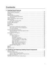
Contents 1 Desktop Board Features Supported Operating Systems 10 Desktop Board Components 11 Processor ...13 Main Memory...13 Intel® G33 Express Chipset 14 Intel G33 Graphics Subsystem 14 Audio Subsystem 16 Legacy Input/Output (I/O) Controller 16 LAN Subsystem 16 RJ-45 LAN ...# Signal Wake-up Support 23 ENERGY STAR* Qualified 24 Speaker...24 Battery ...24 Real-Time Clock 24 2 Installing and Replacing Desktop Board Components Before You Begin 25 Installation Precautions 26 Prevent Power Supply Overload 26 Observe Safety and Regulatory Requirements 26 Installing the I/O Shield...
Contents 1 Desktop Board Features Supported Operating Systems 10 Desktop Board Components 11 Processor ...13 Main Memory...13 Intel® G33 Express Chipset 14 Intel G33 Graphics Subsystem 14 Audio Subsystem 16 Legacy Input/Output (I/O) Controller 16 LAN Subsystem 16 RJ-45 LAN ...# Signal Wake-up Support 23 ENERGY STAR* Qualified 24 Speaker...24 Battery ...24 Real-Time Clock 24 2 Installing and Replacing Desktop Board Components Before You Begin 25 Installation Precautions 26 Prevent Power Supply Overload 26 Observe Safety and Regulatory Requirements 26 Installing the I/O Shield...
Product Guide
Page 6
Intel Desktop Board DG33FB Product Guide Installing and Removing a Processor 29 Installing a Processor 29 Installing the Processor Fan Heat Sink 32 Connecting the Processor Fan Heat Sink Cable 33 Removing the Processor 34 Installing and Removing Memory 34 Guidelines for Dual Channel Memory Configuration 34 Two or Four ...Cables 44 Connecting to the Internal Headers 45 Connecting to the IEEE 1394a Header 46 Installing a Front Panel Audio Solution for Intel® High Definition Audio 46 Connecting to the Serial Port Header 47 Connecting to the Chassis Intrusion Header 47 Connecting to...
Intel Desktop Board DG33FB Product Guide Installing and Removing a Processor 29 Installing a Processor 29 Installing the Processor Fan Heat Sink 32 Connecting the Processor Fan Heat Sink Cable 33 Removing the Processor 34 Installing and Removing Memory 34 Guidelines for Dual Channel Memory Configuration 34 Two or Four ...Cables 44 Connecting to the Internal Headers 45 Connecting to the IEEE 1394a Header 46 Installing a Front Panel Audio Solution for Intel® High Definition Audio 46 Connecting to the Serial Port Header 47 Connecting to the Chassis Intrusion Header 47 Connecting to...

Product Guide
Page 7
... Indicator 23 4. Remove the Protective Socket Cover 30 9. Connecting the Processor Fan Heat Sink Cable to the Processor Fan Header ..........33 13. Installing a PCI Express x16 Card 39 19. Desktop Board DG33FB Components 11 2. Desktop Board DG33FB Mounting Screw Hole Locations 28 6. Remove the Processor from the Protective Processor Cover 31 10. Dual Channel Memory Configuration with Two DIMMs 34...
... Indicator 23 4. Remove the Protective Socket Cover 30 9. Connecting the Processor Fan Heat Sink Cable to the Processor Fan Header ..........33 13. Installing a PCI Express x16 Card 39 19. Desktop Board DG33FB Components 11 2. Desktop Board DG33FB Mounting Screw Hole Locations 28 6. Remove the Processor from the Protective Processor Cover 31 10. Dual Channel Memory Configuration with Two DIMMs 34...
Product Guide
Page 9
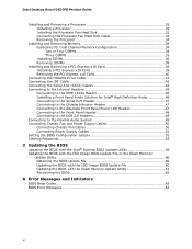
...panel ― One port routed to 8 GB of system memory Intel® G33 Express Chipset consisting of the Desktop Board. Feature Summary Form Factor Processor ATX (320.04 millimeters [11.60 inches] x 243.84 millimeters [9.60 inches]) Support for an Intel® processor in the LGA775 package Main Memory Chipset Graphics Audio • Four... • Four Serial ATA (SATA) channels (3.0 Gb/s), via the ICH9DH • One IDE interface with ATA-66/100 support (two devices) continued 9 1 Desktop Board Features This chapter briefly describes the features of Intel® Desktop Board DG33FB.
...panel ― One port routed to 8 GB of system memory Intel® G33 Express Chipset consisting of the Desktop Board. Feature Summary Form Factor Processor ATX (320.04 millimeters [11.60 inches] x 243.84 millimeters [9.60 inches]) Support for an Intel® processor in the LGA775 package Main Memory Chipset Graphics Audio • Four... • Four Serial ATA (SATA) channels (3.0 Gb/s), via the ICH9DH • One IDE interface with ATA-66/100 support (two devices) continued 9 1 Desktop Board Features This chapter briefly describes the features of Intel® Desktop Board DG33FB.
Product Guide
Page 12
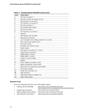
... header Serial ATA connectors (4) IDE connector High-speed USB 2.0 headers (3) IEEE 1394a header Related Links: Go to the following links for more information about: • Desktop Board DG33FB http://www.intel.com/design/motherbd http://support.intel.com/support/motherboards/desktop • Supported processors • Audio software and utilities • LAN software and drivers http://www...
... header Serial ATA connectors (4) IDE connector High-speed USB 2.0 headers (3) IEEE 1394a header Related Links: Go to the following links for more information about: • Desktop Board DG33FB http://www.intel.com/design/motherbd http://support.intel.com/support/motherboards/desktop • Supported processors • Audio software and utilities • LAN software and drivers http://www...

Product Guide
Page 13
.... • Support for normal operation. Desktop Board Features Processor CAUTION Failure to use an appropriate power supply and/or not connecting the 12 V (2 x 2 pin) power connector to the Desktop Board may result in the LGA775 package. Desktop Board DG33FB supports an Intel processor in damage to the Desktop Board through the LGA775 socket. The processor connects to the board, or the system may not...
.... • Support for normal operation. Desktop Board Features Processor CAUTION Failure to use an appropriate power supply and/or not connecting the 12 V (2 x 2 pin) power connector to the Desktop Board may result in the LGA775 package. Desktop Board DG33FB supports an Intel processor in damage to the Desktop Board through the LGA775 socket. The processor connects to the board, or the system may not...

Product Guide
Page 18
...USB 2.0. Enhanced IDE Interface The board's IDE interface handles the exchange of information between the processor and peripheral devices such as CD-ROM drives) • Older PIO Mode devices • Ultra DMA-33 and ATA-66/100 protocols Serial ATA The Desktop Board supports four Serial ATA channels (3.0...(POST), the BIOS Setup program, the PCI/PCI Express and IDE auto-configuration utilities, and the video BIOS. Intel Desktop Board DG33FB Product Guide Hi-Speed USB 2.0 Support The Desktop Board supports up to 12 USB 2.0 ports (six ports routed to the back panel and six ports routed to two ...
...USB 2.0. Enhanced IDE Interface The board's IDE interface handles the exchange of information between the processor and peripheral devices such as CD-ROM drives) • Older PIO Mode devices • Ultra DMA-33 and ATA-66/100 protocols Serial ATA The Desktop Board supports four Serial ATA channels (3.0...(POST), the BIOS Setup program, the PCI/PCI Express and IDE auto-configuration utilities, and the video BIOS. Intel Desktop Board DG33FB Product Guide Hi-Speed USB 2.0 Support The Desktop Board supports up to 12 USB 2.0 ports (six ports routed to the back panel and six ports routed to two ...
Product Guide
Page 20
...Intel Quiet System Technology. • Fan speed controllers and sensors integrated into the ICH9DH • Thermal sensors in the processor, GMCH, and ICH9DH, plus an onboard remote sensor • Thermally monitored closed-loop fan control, for the location of ACPI with the Desktop Board... management NOTE Memory must be installed in the Channel A, DIMM 0 socket to the chassis intrusion header on the Desktop Board. Intel Desktop Board DG33FB Product Guide Hardware Monitoring and Fan Speed Control The features of the hardware monitoring and fan speed control include: • Monitoring...
...Intel Quiet System Technology. • Fan speed controllers and sensors integrated into the ICH9DH • Thermal sensors in the processor, GMCH, and ICH9DH, plus an onboard remote sensor • Thermally monitored closed-loop fan control, for the location of ACPI with the Desktop Board... management NOTE Memory must be installed in the Channel A, DIMM 0 socket to the chassis intrusion header on the Desktop Board. Intel Desktop Board DG33FB Product Guide Hardware Monitoring and Fan Speed Control The features of the hardware monitoring and fan speed control include: • Monitoring...

Product Guide
Page 21
The Desktop Board has a 4-pin processor fan header, and one 4-pin and two 3-pin chassis fan headers....• The fans are off when the computer is in the BIOS Setup program's Boot menu. The Desktop Board has two power connectors. LAN wakeup capabilities enable remote wake-up the computer. 21 The computer's response... headers have a +12 V DC connection. Fan Headers The function/operation of delivering adequate +5 V standby current. Desktop Board Features Hardware Support Power Connectors ATX12V-compliant power supplies can turn off the computer power through a network. When an ...
The Desktop Board has a 4-pin processor fan header, and one 4-pin and two 3-pin chassis fan headers....• The fans are off when the computer is in the BIOS Setup program's Boot menu. The Desktop Board has two power connectors. LAN wakeup capabilities enable remote wake-up the computer. 21 The computer's response... headers have a +12 V DC connection. Fan Headers The function/operation of delivering adequate +5 V standby current. Desktop Board Features Hardware Support Power Connectors ATX12V-compliant power supplies can turn off the computer power through a network. When an ...

Product Guide
Page 25
2 Installing and Replacing Desktop Board Components This chapter tells you begin: • Always follow the ... Follow these guidelines before you how to: • Install the I/O shield • Install and remove the Desktop Board • Install and remove a processor • Install and remove memory • Install and remove a PCI Express x16 card • Connet the ...Perform the procedures described in this chapter. If such a station is off. Some circuitry on the board can continue to a metal part of the procedures described in this chapter assume familiarity with the general...
2 Installing and Replacing Desktop Board Components This chapter tells you begin: • Always follow the ... Follow these guidelines before you how to: • Install the I/O shield • Install and remove the Desktop Board • Install and remove a processor • Install and remove memory • Install and remove a PCI Express x16 card • Connet the ...Perform the procedures described in this chapter. If such a station is off. Some circuitry on the board can continue to a metal part of the procedures described in this chapter assume familiarity with the general...
Product Guide
Page 26
... output. Related Links For information about regulatory compliance, go to Appendix B on the chassis • Hot components (such as processors, voltage regulators, and heat sinks) • Damage to qualified technical personnel. If the instructions for associated modules, contact the supplier... loads of all warnings and cautions in this section and the instructions supplied with the chassis and associated modules. Intel Desktop Board DG33FB Product Guide Installation Precautions When you increase safety risk and the possibility of noncompliance with regional laws and regulations. ...
... output. Related Links For information about regulatory compliance, go to Appendix B on the chassis • Hot components (such as processors, voltage regulators, and heat sinks) • Damage to qualified technical personnel. If the instructions for associated modules, contact the supplier... loads of all warnings and cautions in this section and the instructions supplied with the chassis and associated modules. Intel Desktop Board DG33FB Product Guide Installation Precautions When you increase safety risk and the possibility of noncompliance with regional laws and regulations. ...
Product Guide
Page 29
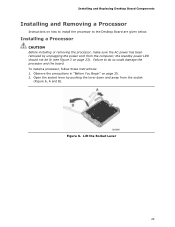
Failure to the Desktop Board are given below. To install a processor, follow these instructions: 1. Open the socket lever by unplugging the power cord from the socket (Figure 6, A and B). Lift the Socket Lever 29 Observe the... Figure 3 on page 25. 2. Installing a Processor CAUTION Before installing or removing the processor, make sure the AC power has been removed by pushing the lever down and away from the computer; Figure 6. Installing and Replacing Desktop Board Components Installing and Removing a Processor Instructions on how to install the processor to do so could damage the...
Failure to the Desktop Board are given below. To install a processor, follow these instructions: 1. Open the socket lever by unplugging the power cord from the socket (Figure 6, A and B). Lift the Socket Lever 29 Observe the... Figure 3 on page 25. 2. Installing a Processor CAUTION Before installing or removing the processor, make sure the AC power has been removed by pushing the lever down and away from the computer; Figure 6. Installing and Replacing Desktop Board Components Installing and Removing a Processor Instructions on how to install the processor to do so could damage the...
Product Guide
Page 30
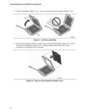
Intel Desktop Board DG33FB Product Guide 3. Figure 7. Lift the load plate (Figure 7, A). Do not touch the socket contacts (Figure 7, B). Do not discard the protective socket cover. Always replace the socket cover if the processor is removed from the load plate (Figure 8). Remove the plastic protective socket cover from the socket. Figure 8. Remove the Protective Socket Cover 30 Lift the Load Plate 4.
Intel Desktop Board DG33FB Product Guide 3. Figure 7. Lift the load plate (Figure 7, A). Do not touch the socket contacts (Figure 7, B). Do not discard the protective socket cover. Always replace the socket cover if the processor is removed from the load plate (Figure 8). Remove the plastic protective socket cover from the socket. Figure 8. Remove the Protective Socket Cover 30 Lift the Load Plate 4.
Product Guide
Page 31
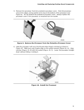
Installing and Replacing Desktop Board Components 5. Always replace the processor cover if the processor is removed from the Protective Processor Cover 6. Make sure your thumb and index fingers oriented as shown in Figure 10. Hold the processor with the socket (Figure 10, C). Install the Processor 31 Align notches (Figure 10, B) with your fingers align to touch the bottom...
Installing and Replacing Desktop Board Components 5. Always replace the processor cover if the processor is removed from the Protective Processor Cover 6. Make sure your thumb and index fingers oriented as shown in Figure 10. Hold the processor with the socket (Figure 10, C). Install the Processor 31 Align notches (Figure 10, B) with your fingers align to touch the bottom...

Product Guide
Page 32
Figure 11. Close the Load Plate Installing the Processor Fan Heat Sink Desktop Board DG33FB has mounting holes for a processor fan heat sink. Pressing down on how to attach the processor fan heat sink to the Desktop Board, refer to the boxed processor manual. 32 For instructions on the load plate (Figure 11, A), close and engage the socket lever (Figure 11, B). Intel Desktop Board DG33FB Product Guide 7.
Figure 11. Close the Load Plate Installing the Processor Fan Heat Sink Desktop Board DG33FB has mounting holes for a processor fan heat sink. Pressing down on how to attach the processor fan heat sink to the Desktop Board, refer to the boxed processor manual. 32 For instructions on the load plate (Figure 11, A), close and engage the socket lever (Figure 11, B). Intel Desktop Board DG33FB Product Guide 7.

Product Guide
Page 33
Connecting the Processor Fan Heat Sink Cable to the 4-pin processor fan header (see Figure 12). A fan with a 3-pin connector cannot use the onboard fan control, the fan will always operate at full speed. However, since a fan with a 4-pin connector as shown in Figure 12, A is recommended; Figure 12. however, a fan with a 3-pin connector (Figure 12, B) can be used. Installing and Replacing Desktop Board Components Connecting the Processor Fan Heat Sink Cable Connect the processor fan heat sink cable to the Processor Fan Header 33
Connecting the Processor Fan Heat Sink Cable to the 4-pin processor fan header (see Figure 12). A fan with a 3-pin connector cannot use the onboard fan control, the fan will always operate at full speed. However, since a fan with a 4-pin connector as shown in Figure 12, A is recommended; Figure 12. however, a fan with a 3-pin connector (Figure 12, B) can be used. Installing and Replacing Desktop Board Components Connecting the Processor Fan Heat Sink Cable Connect the processor fan heat sink cable to the Processor Fan Header 33

Product Guide
Page 34
... pair of DIMMs equal in speed and size (see Figure 13) in both Channel A and Channel B. Intel Desktop Board DG33FB Product Guide Removing the Processor For instructions on how to remove the processor fan heat sink and processor, refer to the processor installation manual. Installing and Removing Memory NOTE To be populated. NOTE Regardless of the memory configuration...
... pair of DIMMs equal in speed and size (see Figure 13) in both Channel A and Channel B. Intel Desktop Board DG33FB Product Guide Removing the Processor For instructions on how to remove the processor fan heat sink and processor, refer to the processor installation manual. Installing and Removing Memory NOTE To be populated. NOTE Regardless of the memory configuration...
Product Guide
Page 51
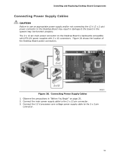
...Supply Cables 1. Observe the precautions in damage to the board or the system may result in "Before You Begin" on the Desktop Board is backwards compatible with ATX12V power supplies with 2 x 10 connectors. Figure 26. Connect the 12 V processor core voltage power supply cable to the 2 x 12... pin connector. 3. Connect the main power supply cable to the 2 x 2 pin connector. 51 Installing and Replacing Desktop Board Components Connecting Power Supply Cables CAUTION Failure to use an...
...Supply Cables 1. Observe the precautions in damage to the board or the system may result in "Before You Begin" on the Desktop Board is backwards compatible with ATX12V power supplies with 2 x 10 connectors. Figure 26. Connect the 12 V processor core voltage power supply cable to the 2 x 12... pin connector. 3. Connect the main power supply cable to the 2 x 2 pin connector. 51 Installing and Replacing Desktop Board Components Connecting Power Supply Cables CAUTION Failure to use an...
Product Guide
Page 63
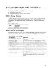
... 12 lists the BIOS codes. The firmware has detected that a Single-Bit ECC Error occurred. Beep Codes Beep 3 Siren Description No memory Processor overheat (on the monitor BIOS Beep Codes The BIOS also issues a beep code (one long tone followed by two short tones) during the...to a thermal event (overheating). Table 12. The firmware has detected that the system date/time has not been set. A Error Messages and Indicators Desktop Board DG33FB reports POST errors in two ways: • By sounding a beep code • By displaying an error message on reboot) BIOS Error Messages ...
... 12 lists the BIOS codes. The firmware has detected that a Single-Bit ECC Error occurred. Beep Codes Beep 3 Siren Description No memory Processor overheat (on the monitor BIOS Beep Codes The BIOS also issues a beep code (one long tone followed by two short tones) during the...to a thermal event (overheating). Table 12. The firmware has detected that the system date/time has not been set. A Error Messages and Indicators Desktop Board DG33FB reports POST errors in two ways: • By sounding a beep code • By displaying an error message on reboot) BIOS Error Messages ...


