

Product Guide
Page 5
... BIOS ...18 Serial ATA and IDE Auto Configuration 18 PCI and PCI Express Auto Configuration 18 Security Passwords ...18 Chassis Intrusion...19 Power Management Features 19 ACPI...19 Power Connectors...19 Fan Connectors...19 Fan Speed Control (Intel® Precision Cooling Technology 19 Suspend to RAM (Instantly... Precautions ...24 Installation Instructions...24 Ensure Electromagnetic Compatibility (EMC) Compliance 24 Chassis and Component Certifications 25 Prevent Power Supply Overload 25 Place Battery Marking 25 Use Only for Intended Applications 26 Installing the I/O Shield ...26 v
... BIOS ...18 Serial ATA and IDE Auto Configuration 18 PCI and PCI Express Auto Configuration 18 Security Passwords ...18 Chassis Intrusion...19 Power Management Features 19 ACPI...19 Power Connectors...19 Fan Connectors...19 Fan Speed Control (Intel® Precision Cooling Technology 19 Suspend to RAM (Instantly... Precautions ...24 Installation Instructions...24 Ensure Electromagnetic Compatibility (EMC) Compliance 24 Chassis and Component Certifications 25 Prevent Power Supply Overload 25 Place Battery Marking 25 Use Only for Intended Applications 26 Installing the I/O Shield ...26 v

Product Guide
Page 6
...D945PSN Product Guide Installing and Removing the Desktop Board 27 Installing and Removing a Processor 28 Installing a Processor 28 Installing the Processor Fan Heat Sink 31 Connecting the Processor Fan Heat Sink Cable 31 Removing the Processor 31 Installing and Removing Memory 32 Installing DIMMs...34 Removing DIMMs...35 Installing and Removing a PCI...for Intel® High Definition Audio 40 Connecting USB 2.0 Headers 41 Connecting IEEE 1394a Headers 41 Connecting the Front Panel Header 41 Setting Up the Flexible 6- Channel Audio with Jack Re-tasking 42 Connecting Fan and Power ...
...D945PSN Product Guide Installing and Removing the Desktop Board 27 Installing and Removing a Processor 28 Installing a Processor 28 Installing the Processor Fan Heat Sink 31 Connecting the Processor Fan Heat Sink Cable 31 Removing the Processor 31 Installing and Removing Memory 32 Installing DIMMs...34 Removing DIMMs...35 Installing and Removing a PCI...for Intel® High Definition Audio 40 Connecting USB 2.0 Headers 41 Connecting IEEE 1394a Headers 41 Connecting the Front Panel Header 41 Setting Up the Flexible 6- Channel Audio with Jack Re-tasking 42 Connecting Fan and Power ...
Product Guide
Page 7
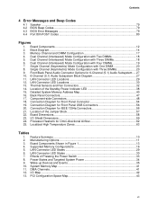
...Connectors for the BIOS Setup Program Modes 46 12. Connecting Power Supply Cables 44 24. Desktop Board D945PSN Components 12 3. Lead-Free Board Markings 64 16. LAN... Dual Configuration Example 3 33 16. Power Supply Requirements 13 4. IEEE 1394a Header Signal Names 41 10. Inserting a PCI Express x16 Card 36 18. Jumper ...D945PSN Components 11 2. Location of Other Connectors on Desktop Board D945PSN 45 25. Removing the Battery 52 27. F2 Key ...53 Tables 1. Desktop Board D945PSN Memory Configurations 14 5. Front Panel Audio Header Signal Names for Intel...
...Connectors for the BIOS Setup Program Modes 46 12. Connecting Power Supply Cables 44 24. Desktop Board D945PSN Components 12 3. Lead-Free Board Markings 64 16. LAN... Dual Configuration Example 3 33 16. Power Supply Requirements 13 4. IEEE 1394a Header Signal Names 41 10. Inserting a PCI Express x16 Card 36 18. Jumper ...D945PSN Components 11 2. Location of Other Connectors on Desktop Board D945PSN 45 25. Removing the Battery 52 27. F2 Key ...53 Tables 1. Desktop Board D945PSN Memory Configurations 14 5. Front Panel Audio Header Signal Names for Intel...

Product Guide
Page 10
...memory • Support for SMBIOS • Intel® Rapid BIOS Boot • Intel® Express BIOS Update Power Management • Support for Advanced Configuration and Power Interface (ACPI) • Suspend to RAM (STR) • Wake on USB, PCI, PCI Express, PS/2, LAN, and front panel Hardware...out of range values Related Links: For more information about Desktop Board D945PSN, including the Technical Product Specification (TPS), BIOS updates, and device drivers, go to: http://support.intel.com/support/motherboards/desktop/ Supported Operating Systems The desktop board supports the ...
...memory • Support for SMBIOS • Intel® Rapid BIOS Boot • Intel® Express BIOS Update Power Management • Support for Advanced Configuration and Power Interface (ACPI) • Suspend to RAM (STR) • Wake on USB, PCI, PCI Express, PS/2, LAN, and front panel Hardware...out of range values Related Links: For more information about Desktop Board D945PSN, including the Technical Product Specification (TPS), BIOS updates, and device drivers, go to: http://support.intel.com/support/motherboards/desktop/ Supported Operating Systems The desktop board supports the ...
Product Guide
Page 12
... panel header Alternate power LED header Hi-speed USB 2.0 headers IEEE 1394a headers PCI bus add-in card connectors Related Links: Go to the following links for more information about: • Desktop Board D945PSN • Supported ...processors • Audio software and utilities • LAN software and drivers http://www.intel.com/design/motherbd http://support.intel.com/support/motherboards/desktop http://support.intel.com/support/motherboards/desktop http://www.intel.com/design/motherbd http://www.intel.com/design/motherbd 12 Intel Desktop Board D945PSN...
... panel header Alternate power LED header Hi-speed USB 2.0 headers IEEE 1394a headers PCI bus add-in card connectors Related Links: Go to the following links for more information about: • Desktop Board D945PSN • Supported ...processors • Audio software and utilities • LAN software and drivers http://www.intel.com/design/motherbd http://support.intel.com/support/motherboards/desktop http://support.intel.com/support/motherboards/desktop http://www.intel.com/design/motherbd http://www.intel.com/design/motherbd 12 Intel Desktop Board D945PSN...
Product Guide
Page 14
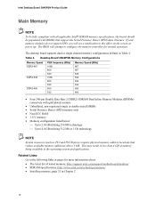
... supports dual or single channel memory configurations defined in Chapter 2 14 Intel Desktop Board D945PSN Product Guide Main Memory NOTE To be fully compliant with all applicable Intel® SDRAM memory specifications, the board should be populated with gold ...256 Mb technology ⎯ Up to 4.0 GB utilizing 512 Mb or 1 Gb technology NOTE System resources (such as PCI and PCI Express) require physical memory address locations that support the Serial Presence Detect (SPD) data structure. If your memory modules...applications. Related Links: Go to this effect on the screen at power up.
... supports dual or single channel memory configurations defined in Chapter 2 14 Intel Desktop Board D945PSN Product Guide Main Memory NOTE To be fully compliant with all applicable Intel® SDRAM memory specifications, the board should be populated with gold ...256 Mb technology ⎯ Up to 4.0 GB utilizing 512 Mb or 1 Gb technology NOTE System resources (such as PCI and PCI Express) require physical memory address locations that support the Serial Presence Detect (SPD) data structure. If your memory modules...applications. Related Links: Go to this effect on the screen at power up.

Product Guide
Page 16
...one 1.2 MB or 1.44 MB diskette drive • Intelligent power management, including a programmable wake up event interface • PCI power management support LAN Subsystem The LAN, with the Intel 82801GB (ICH7), provides the following functions: • Support for Intel 82573V or 82573L 10/100/1000 Gigabit Ethernet LAN • ...EEPROM that contains the MAC address LAN Subsystem Software For LAN software and drivers, refer to the D945PSN link on Intel's World Wide Web site at: http://support.intel.com/support/motherboards/desktop RJ-45 LAN Connector LEDs Two LEDs are built into the RJ-45 LAN...
...one 1.2 MB or 1.44 MB diskette drive • Intelligent power management, including a programmable wake up event interface • PCI power management support LAN Subsystem The LAN, with the Intel 82801GB (ICH7), provides the following functions: • Support for Intel 82573V or 82573L 10/100/1000 Gigabit Ethernet LAN • ...EEPROM that contains the MAC address LAN Subsystem Software For LAN software and drivers, refer to the D945PSN link on Intel's World Wide Web site at: http://support.intel.com/support/motherboards/desktop RJ-45 LAN Connector LEDs Two LEDs are built into the RJ-45 LAN...
Product Guide
Page 18
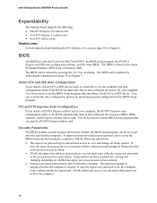
... are then available for viewing and changing depending on page 53 in Chapter 3. BIOS The BIOS provides the Power-On Self-Test (POST), the BIOS Setup program, the PCI/PCI Express and IDE auto-configuration utilities, and the video BIOS. You do not need to run the BIOS Setup... If only the supervisor password is stored in Chapter 2. Intel Desktop Board D945PSN Product Guide Expandability The desktop board supports the following: • One PCI Express x16 add-in card • Two PCI Express x1 add-in card • Four PCI add-in cards Related Links: For information about installing the...
... are then available for viewing and changing depending on page 53 in Chapter 3. BIOS The BIOS provides the Power-On Self-Test (POST), the BIOS Setup program, the PCI/PCI Express and IDE auto-configuration utilities, and the video BIOS. You do not need to run the BIOS Setup... If only the supervisor password is stored in Chapter 2. Intel Desktop Board D945PSN Product Guide Expandability The desktop board supports the following: • One PCI Express x16 add-in card • Two PCI Express x1 add-in card • Four PCI add-in cards Related Links: For information about installing the...

Product Guide
Page 20
... http://support.intel.com/support/...PCI and/or USB buses exceeds power supply capacity...power to provide adequate standby current when using this desktop board must be able to provide enough standby current to any controlled chassis fan header. The desktop board's standby power... indicator, shown in memory. If the system has a dual-colored power LED on system configuration and environment. Location of Standby Power...power supply must be capable of delivering adequate +5 V standby current. This includes the memory modules and PCI...Power supplies used with this feature can damage the power...
... http://support.intel.com/support/...PCI and/or USB buses exceeds power supply capacity...power to provide adequate standby current when using this desktop board must be able to provide enough standby current to any controlled chassis fan header. The desktop board's standby power... indicator, shown in memory. If the system has a dual-colored power LED on system configuration and environment. Location of Standby Power...power supply must be capable of delivering adequate +5 V standby current. This includes the memory modules and PCI...Power supplies used with this feature can damage the power...

Product Guide
Page 21
PME# Wakeup Support When the PME# signal on how to replace the battery. Go to page 48 for instructions on the PCI bus is asserted, the computer wakes from USB. Real-Time Clock The desktop board has a time-of a USB peripheral that supports wake from an ACPI ... values in CMOS RAM and the clock current when the computer is turned off . The speaker provides audible error code (beep code) information during the Power-On Self-Test (POST). Battery A battery on the desktop board. The battery on the desktop board keeps the clock current when the computer is turned...
PME# Wakeup Support When the PME# signal on how to replace the battery. Go to page 48 for instructions on the PCI bus is asserted, the computer wakes from USB. Real-Time Clock The desktop board has a time-of a USB peripheral that supports wake from an ACPI ... values in CMOS RAM and the clock current when the computer is turned off . The speaker provides audible error code (beep code) information during the Power-On Self-Test (POST). Battery A battery on the desktop board. The battery on the desktop board keeps the clock current when the computer is turned...
Product Guide
Page 23
... front panel power button is off. Some circuitry on the board can result in this chapter. NOTE Refer to : • Install the I/O shield • Install and remove the desktop board • Install and remove a processor and memory • Install and remove a PCI Express x16 ... 2 Installing and Replacing Desktop Board Components This chapter tells you open the computer or perform any procedures can continue to disconnect power, telecommunications links, networks, or modems before performing any of the procedures described in this chapter assume familiarity with the general terminology...
... front panel power button is off. Some circuitry on the board can result in this chapter. NOTE Refer to : • Install the I/O shield • Install and remove the desktop board • Install and remove a processor and memory • Install and remove a PCI Express x16 ... 2 Installing and Replacing Desktop Board Components This chapter tells you open the computer or perform any procedures can continue to disconnect power, telecommunications links, networks, or modems before performing any of the procedures described in this chapter assume familiarity with the general terminology...

Product Guide
Page 34
...power cord. 34 Remove the computer's cover and locate the DIMM sockets (see inset in Figure 16). 8. Remove the PCI Express video card if it was removed prior to installing the DIMMs. 11. Position the DIMM above the socket. Make sure the clips are pushed outward to the open position. 6. Intel Desktop Board D945PSN... Product Guide Installing DIMMs NOTE Install memory in the DIMM sockets prior to installing a PCI Express video card to avoid interference with the keys in the socket (see Figure...
...power cord. 34 Remove the computer's cover and locate the DIMM sockets (see inset in Figure 16). 8. Remove the PCI Express video card if it was removed prior to installing the DIMMs. 11. Position the DIMM above the socket. Make sure the clips are pushed outward to the open position. 6. Intel Desktop Board D945PSN... Product Guide Installing DIMMs NOTE Install memory in the DIMM sockets prior to installing a PCI Express video card to avoid interference with the keys in the socket (see Figure...

Product Guide
Page 35
... reach the DIMM sockets. 10. Remove the PCI Express card if it interferes with the DIMM clips from the computer. 4. Observe the precautions in an anti-static package. 8. The DIMM pops out of the DIMM socket. Replace the computer's cover and reconnect the AC power cord. 35 Hold the DIMM by the... edges, lift it away from the socket, and store it before taking out the DIMM. 9. Turn off the computer. 3. Gently spread the retaining clips at each end of the socket. 7. Reinstall the PCI Express card if you removed or...
... reach the DIMM sockets. 10. Remove the PCI Express card if it interferes with the DIMM clips from the computer. 4. Observe the precautions in an anti-static package. 8. The DIMM pops out of the DIMM socket. Replace the computer's cover and reconnect the AC power cord. 35 Hold the DIMM by the... edges, lift it away from the socket, and store it before taking out the DIMM. 9. Turn off the computer. 3. Gently spread the retaining clips at each end of the socket. 7. Reinstall the PCI Express card if you removed or...

Product Guide
Page 36
... card straight up. 36 Observe the precautions in "Before You Begin" on page 23. 2. Intel Desktop Board D945PSN Product Guide Installing and Removing a PCI Express x16 Card CAUTION When installing any PCI Express x16 card on the desktop board, ensure that secures the card's metal bracket to remove ... seated in the PCI Express x16 connector before you power on the over-current protection of the power supply, certain board components and/or traces may result across the PCI Express connector pins. Depending on the system. Inserting a PCI Express x16 Card Removing the PCI Express x16 Card ...
... card straight up. 36 Observe the precautions in "Before You Begin" on page 23. 2. Intel Desktop Board D945PSN Product Guide Installing and Removing a PCI Express x16 Card CAUTION When installing any PCI Express x16 card on the desktop board, ensure that secures the card's metal bracket to remove ... seated in the PCI Express x16 connector before you power on the over-current protection of the power supply, certain board components and/or traces may result across the PCI Express connector pins. Depending on the system. Inserting a PCI Express x16 Card Removing the PCI Express x16 Card ...

Product Specification
Page 5
...Support ...15 1.3 Processor ...15 1.4 System Memory ...16 1.4.1 Memory Configurations 17 1.5 Intel® 945P Chipset...21 1.5.1 USB ...21 1.5.2 IDE Support 22 1.5.3 Real-Time Clock, CMOS SRAM, and Battery 24 1.6 PCI Express Connectors 24 1.7 IEEE-1394a Connectors (Optional 24 1.8 Legacy I/O Controller 25 1.8.1... and Fan Control ASIC 31 1.11.2 Chassis Intrusion and Detection 31 1.11.3 Fan Monitoring 31 1.11.4 Thermal Monitoring 32 1.12 Power Management ...33 1.12.1 ACPI ...33 1.12.2 Hardware Support 35 1.13 Trusted Platform Module (Optional 38 2 Technical Reference 2.1 Introduction...
...Support ...15 1.3 Processor ...15 1.4 System Memory ...16 1.4.1 Memory Configurations 17 1.5 Intel® 945P Chipset...21 1.5.1 USB ...21 1.5.2 IDE Support 22 1.5.3 Real-Time Clock, CMOS SRAM, and Battery 24 1.6 PCI Express Connectors 24 1.7 IEEE-1394a Connectors (Optional 24 1.8 Legacy I/O Controller 25 1.8.1... and Fan Control ASIC 31 1.11.2 Chassis Intrusion and Detection 31 1.11.3 Fan Monitoring 31 1.11.4 Thermal Monitoring 32 1.12 Power Management ...33 1.12.1 ACPI ...33 1.12.2 Hardware Support 35 1.13 Trusted Platform Module (Optional 38 2 Technical Reference 2.1 Introduction...

Product Specification
Page 6
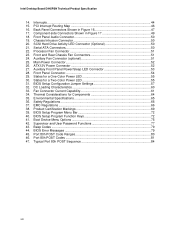
Intel Desktop Board D945PSN Technical Product Specification 2.4 Fixed I/O Map...42 2.5 PCI Configuration Space Map 43 2.6 Interrupts ...44 2.7 PCI Conventional Interrupt Routing Map 45 2.8 Connectors...46 2.8.1... Back Panel Connectors 47 2.8.2 Component-side Connectors 48 2.9 Jumper Block ...57 2.10 Mechanical Considerations 58 2.10.1 Form Factor 58 2.10.2 I/O Shield...59 2.11 Electrical Considerations 60 2.11.1 DC Loading...60 2.11.2 Add-in Board Considerations 60 2.11.3 Fan Connector Current Capability 61 2.11.4 Power...
Intel Desktop Board D945PSN Technical Product Specification 2.4 Fixed I/O Map...42 2.5 PCI Configuration Space Map 43 2.6 Interrupts ...44 2.7 PCI Conventional Interrupt Routing Map 45 2.8 Connectors...46 2.8.1... Back Panel Connectors 47 2.8.2 Component-side Connectors 48 2.9 Jumper Block ...57 2.10 Mechanical Considerations 58 2.10.1 Form Factor 58 2.10.2 I/O Shield...59 2.11 Electrical Considerations 60 2.11.1 DC Loading...60 2.11.2 Add-in Board Considerations 60 2.11.3 Fan Connector Current Capability 61 2.11.4 Power...
Product Specification
Page 7
.... Detailed System Memory Address Map 40 16. Connection Diagram for IEEE 1394a Connectors 56 21. Location of Pressing the Power Switch 33 8. PCI Configuration Space Map 43 vii Block Diagram...14 3. LAN Connector LED Locations 29 12. Connection Diagram for Front Panel ...6-Channel (5.1) Audio Subsystem .... 27 10. 6-Channel (5.1) Audio Subsystem Block Diagram 27 11. Effects of the Jumper Block 57 22. Power States and Targeted System Power 34 9. I /O Map ...42 13. Connection Diagram for Front Panel Connector 54 19. Supported Memory Configurations 16 5. Dual Channel (...
.... Detailed System Memory Address Map 40 16. Connection Diagram for IEEE 1394a Connectors 56 21. Location of Pressing the Power Switch 33 8. PCI Configuration Space Map 43 vii Block Diagram...14 3. LAN Connector LED Locations 29 12. Connection Diagram for Front Panel ...6-Channel (5.1) Audio Subsystem .... 27 10. 6-Channel (5.1) Audio Subsystem Block Diagram 27 11. Effects of the Jumper Block 57 22. Power States and Targeted System Power 34 9. I /O Map ...42 13. Connection Diagram for Front Panel Connector 54 19. Supported Memory Configurations 16 5. Dual Channel (...
Product Specification
Page 8
...Panel Audio Connector 50 19. SCSI Hard Drive Activity LED Connector (Optional 50 21. Main Power Connector 52 26. EMC Regulations ...66 38. PCI Interrupt Routing Map 46 16. ATX12V Power Connector 52 27. BIOS Setup Program Menu Bar 72 40. BIOS Setup Program Function Keys... a Two-Color Power LED 55 31. BIOS Error Messages 79 45. States for a One-Color Power LED 55 30. Typical Port 80h POST Sequence 84 viii BIOS Setup Configuration Jumper Settings 57 32. Thermal Considerations for Components 64 35. Intel Desktop Board D945PSN Technical Product Specification ...
...Panel Audio Connector 50 19. SCSI Hard Drive Activity LED Connector (Optional 50 21. Main Power Connector 52 26. EMC Regulations ...66 38. PCI Interrupt Routing Map 46 16. ATX12V Power Connector 52 27. BIOS Setup Program Menu Bar 72 40. BIOS Setup Program Function Keys... a Two-Color Power LED 55 31. BIOS Error Messages 79 45. States for a One-Color Power LED 55 30. Typical Port 80h POST Sequence 84 viii BIOS Setup Configuration Jumper Settings 57 32. Thermal Considerations for Components 64 35. Intel Desktop Board D945PSN Technical Product Specification ...

Product Specification
Page 9
1 Product Description What This Chapter Contains 1.1 Overview ...10 1.2 Online Support ...15 1.3 Processor ...15 1.4 System Memory ...16 1.5 Intel® 945P Chipset...21 1.6 PCI Express Connectors 24 1.7 IEEE-1394a Connectors (Optional 24 1.8 Legacy I/O Controller 25 1.9 Audio Subsystem ...26 1.10 LAN Subsystem ...28 1.11 Hardware Management Subsystem 31 1.12 Power Management ...33 1.13 Trusted Platform Module (Optional 38 9
1 Product Description What This Chapter Contains 1.1 Overview ...10 1.2 Online Support ...15 1.3 Processor ...15 1.4 System Memory ...16 1.5 Intel® 945P Chipset...21 1.6 PCI Express Connectors 24 1.7 IEEE-1394a Connectors (Optional 24 1.8 Legacy I/O Controller 25 1.9 Audio Subsystem ...26 1.10 LAN Subsystem ...28 1.11 Hardware Management Subsystem 31 1.12 Power Management ...33 1.13 Trusted Platform Module (Optional 38 9
Product Specification
Page 10
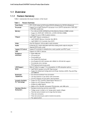
... Board D945PSN Technical Product Specification 1.1 Overview 1.1.1 Feature Summary Table 1 summarizes the major features of LAN subsystem options. BIOS Expansion Capabilities Instantly Available PC Technology Hardware Monitor Subsystem • Intel® BIOS (resident in the SPI Flash device) • Support for Advanced Configuration and Power Interface (ACPI), Plug and Play, and SMBIOS • Four PCI...
... Board D945PSN Technical Product Specification 1.1 Overview 1.1.1 Feature Summary Table 1 summarizes the major features of LAN subsystem options. BIOS Expansion Capabilities Instantly Available PC Technology Hardware Monitor Subsystem • Intel® BIOS (resident in the SPI Flash device) • Support for Advanced Configuration and Power Interface (ACPI), Plug and Play, and SMBIOS • Four PCI...


