Product Guide
Page 7
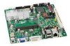
...LED Blink and Internal Speaker Beep Codes 59 26. Location of the Chassis Fan Header 46 16. Removing the Battery 53 18. Intel Desktop Board D945GSEJT China RoHS Material Self Declaration Table .........68 Tables 1. Feature Summary 9 2. Chassis Fan Header 38 10. LAN Status LEDs 18 ... Audio Header for Front Panel Header 43 13. Front Panel USB Header 41 19. Intel Desktop Board D945GSEJT Components 12 2. Removing System Memory 32 8. Connecting the SATA Data and Power Cables 33 9. Installing a Wireless LAN Card 34 10. Internal Headers and Connectors 36 12...
...LED Blink and Internal Speaker Beep Codes 59 26. Location of the Chassis Fan Header 46 16. Removing the Battery 53 18. Intel Desktop Board D945GSEJT China RoHS Material Self Declaration Table .........68 Tables 1. Feature Summary 9 2. Chassis Fan Header 38 10. LAN Status LEDs 18 ... Audio Header for Front Panel Header 43 13. Front Panel USB Header 41 19. Intel Desktop Board D945GSEJT Components 12 2. Removing System Memory 32 8. Connecting the SATA Data and Power Cables 33 9. Installing a Wireless LAN Card 34 10. Internal Headers and Connectors 36 12...
Product Guide
Page 19
... 2.0 Support The Desktop Board supports up to seven USB 2.0 ports (three ports routed to the back panel and four ports routed to USB 1.1 operation. USB 1.1 devices will function normally at USB 1.1 speeds. USB 2.0 support requires both an operating system and drivers that have an unshielded cable attached to a ...is compatible with USB 1.1 devices. One of the front panel USB headers supports an Intel Z-U130 USB Solid-State Drive (or compatible device). This may be used to add storage capability to the cable. The PATA interface also supports ATAPI devices (such as CD-ROM drives) and ...
... 2.0 Support The Desktop Board supports up to seven USB 2.0 ports (three ports routed to the back panel and four ports routed to USB 1.1 operation. USB 1.1 devices will function normally at USB 1.1 speeds. USB 2.0 support requires both an operating system and drivers that have an unshielded cable attached to a ...is compatible with USB 1.1 devices. One of the front panel USB headers supports an Intel Z-U130 USB Solid-State Drive (or compatible device). This may be used to add storage capability to the cable. The PATA interface also supports ATAPI devices (such as CD-ROM drives) and ...
Product Guide
Page 27
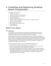
... components. If such a station is off. Failure to disconnect power, telecommunications links, networks, or modems before you begin installing the Desktop Board: • Always follow the steps in each procedure in the correct order. • Set up a log to record information about... Install and remove the Desktop Board • Install and remove system memory • Connect SATA drives • Install a Wireless LAN card • Install an Intel Z-U130 USB Solid-State Drive (or compatible device) • Connect to internal headers • Connect a chassis fan cable • Set the BIOS...
... components. If such a station is off. Failure to disconnect power, telecommunications links, networks, or modems before you begin installing the Desktop Board: • Always follow the steps in each procedure in the correct order. • Set up a log to record information about... Install and remove the Desktop Board • Install and remove system memory • Connect SATA drives • Install a Wireless LAN card • Install an Intel Z-U130 USB Solid-State Drive (or compatible device) • Connect to internal headers • Connect a chassis fan cable • Set the BIOS...
Product Guide
Page 32
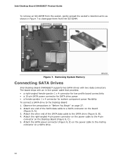
... with two data connectors. Attach the right-angled 4-pin power connector on the power cable to the SATA drive (Figure 8, B). 4. Attach one end of the SATA data cable to the 4-pin connector on the board (Figure 8, A). 3. Intel Desktop Board D945GSEJT Product Guide To remove an SO-DIMM from the SO-DIMM. Observe the precautions in "Before You...
... with two data connectors. Attach the right-angled 4-pin power connector on the power cable to the SATA drive (Figure 8, B). 4. Attach one end of the SATA data cable to the 4-pin connector on the board (Figure 8, A). 3. Intel Desktop Board D945GSEJT Product Guide To remove an SO-DIMM from the SO-DIMM. Observe the precautions in "Before You...

Product Guide
Page 33
Connecting the SATA Data and Power Cables 33 Installing and Replacing Desktop Board Components Figure 8.
Connecting the SATA Data and Power Cables 33 Installing and Replacing Desktop Board Components Figure 8.

Product Guide
Page 36
Intel Desktop Board D945GSEJT Product Guide Connecting to the Internal Headers and Connectors Before connecting cables to the internal headers or connectors, observe the precautions in Figure 11. Internal Headers and Connectors 36 Figure 11. Figure 11 shows the location of the board's internal connectors and headers; Table 5 describes the internal connectors and headers identified in "Before You Begin" on page 27.
Intel Desktop Board D945GSEJT Product Guide Connecting to the Internal Headers and Connectors Before connecting cables to the internal headers or connectors, observe the precautions in Figure 11. Internal Headers and Connectors 36 Figure 11. Figure 11 shows the location of the board's internal connectors and headers; Table 5 describes the internal connectors and headers identified in "Before You Begin" on page 27.
Product Guide
Page 46
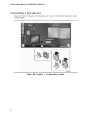
Intel Desktop Board D945GSEJT Product Guide Connecting a Chassis Fan Figure 15 shows the location of the Chassis Fan Header 46 Figure 15. Connect the chassis fan cable to this header. Location of the chassis fan header.
Intel Desktop Board D945GSEJT Product Guide Connecting a Chassis Fan Figure 15 shows the location of the Chassis Fan Header 46 Figure 15. Connect the chassis fan cable to this header. Location of the chassis fan header.

Product Guide
Page 53
... cover. Turn off all peripheral devices connected to the board with a non-permanent adhesive pad. 7. Connect the cable on the new battery to the Desktop Board battery connector and reattach the battery to the board. 8. Removing the Battery 53 Disconnect the computer's power cord from the Desktop Board battery connector (Figure 17, A). 6. Observe the precautions in "Before...
... cover. Turn off all peripheral devices connected to the board with a non-permanent adhesive pad. 7. Connect the cable on the new battery to the Desktop Board battery connector and reattach the battery to the board. 8. Removing the Battery 53 Disconnect the computer's power cord from the Desktop Board battery connector (Figure 17, A). 6. Observe the precautions in "Before...

Product Guide
Page 70
Intel Desktop Board D945GSEJT Product Guide Korean Class B statement translation: This is certified to the following when reading the installation instructions for the host chassis, power supply, and other modules: • Product certifications or lack of certifications • External I/O cable shielding and filtering • ...use this equipment in residential environments and other modules or peripherals, as applicable, are not Class B EMC compliant before integration, then EMC testing may be hazardous If the power supply and other modules or peripherals, as applicable, have passed ...
Intel Desktop Board D945GSEJT Product Guide Korean Class B statement translation: This is certified to the following when reading the installation instructions for the host chassis, power supply, and other modules: • Product certifications or lack of certifications • External I/O cable shielding and filtering • ...use this equipment in residential environments and other modules or peripherals, as applicable, are not Class B EMC compliant before integration, then EMC testing may be hazardous If the power supply and other modules or peripherals, as applicable, have passed ...

Product Guide
Page 72
...United States A certification mark by a Nationally Recognized Testing Laboratory (NRTL) such as the power supply, peripheral drives, wiring, and cables; In Canada A nationally recognized certification mark such as applicable), should be UL listed or recognized and suitable for the intended use ...Canadian EMC regulations. 72 The FCC Class B logo for the country or market where used. Wiring and cables must also be obtained. Intel Desktop Board D945GSEJT Product Guide Chassis and Component Certifications Ensure that the chassis and certain components; If the chassis and other directives...
...United States A certification mark by a Nationally Recognized Testing Laboratory (NRTL) such as the power supply, peripheral drives, wiring, and cables; In Canada A nationally recognized certification mark such as applicable), should be UL listed or recognized and suitable for the intended use ...Canadian EMC regulations. 72 The FCC Class B logo for the country or market where used. Wiring and cables must also be obtained. Intel Desktop Board D945GSEJT Product Guide Chassis and Component Certifications Ensure that the chassis and certain components; If the chassis and other directives...

