Product Guide
Page 7
... Front-panel Power LED Blink and Internal Speaker Beep Codes 59 26. Intel Desktop Board D945GSEJT Mounting Screw Holes 30 6. Connecting the SATA Data and Power Cables 33 9. Connection Diagram for the BIOS Setup Program Modes 48 24. PS/2 Keyboard Port Header...Panel Wireless Activity LED Header 40 14. Contents Figures 1. LAN Status LEDs 18 3. Installing System Memory 31 7. Connection Diagram for BIOS Recovery 57 25. Intel Desktop Board D945GSEJT China RoHS Material Self Declaration Table .........68 Tables 1. ENERGY STAR Requirements 25 5. Serial Port Header (COM 1 and...
... Front-panel Power LED Blink and Internal Speaker Beep Codes 59 26. Intel Desktop Board D945GSEJT Mounting Screw Holes 30 6. Connecting the SATA Data and Power Cables 33 9. Connection Diagram for the BIOS Setup Program Modes 48 24. PS/2 Keyboard Port Header...Panel Wireless Activity LED Header 40 14. Contents Figures 1. LAN Status LEDs 18 3. Installing System Memory 31 7. Connection Diagram for BIOS Recovery 57 25. Intel Desktop Board D945GSEJT China RoHS Material Self Declaration Table .........68 Tables 1. ENERGY STAR Requirements 25 5. Serial Port Header (COM 1 and...

Product Guide
Page 42
Intel Desktop Board D945GSEJT Product Guide Power Supply Connectors The board has the following power supply connectors: • External Power Supply - ATX12V Power Connector Pin Signal Name Pin 1 Ground 2 3 +12 V 4 Signal Name Ground +12 V NOTE Use of the front panel header. It is the system integrator...the inner contact is 12 V and the shell is a connection diagram for the ATX12V power connector are shown in potential damage to the desktop board, power supplies, or other hardware. However, the Desktop Board also provides an internal 2 x 2 power connector that can ...
Intel Desktop Board D945GSEJT Product Guide Power Supply Connectors The board has the following power supply connectors: • External Power Supply - ATX12V Power Connector Pin Signal Name Pin 1 Ground 2 3 +12 V 4 Signal Name Ground +12 V NOTE Use of the front panel header. It is the system integrator...the inner contact is 12 V and the shell is a connection diagram for the ATX12V power connector are shown in potential damage to the desktop board, power supplies, or other hardware. However, the Desktop Board also provides an internal 2 x 2 power connector that can ...

Product Guide
Page 43
Installing and Replacing Desktop Board Components Table 21. Connection Diagram for Front Panel Header Hard Drive Activity LED Pins Pins ...drive connected to an onboard SATA connector • A PATA hard drive connected to an onboard PATA connector • Intel Z-U130 USB Solid State Drive (or compatible device) connected to one of the front panel USB headers Reset Switch... Ground In Power switch Ground Not Connected N/C Not connected Figure 12. When the switch is closed, the board resets and runs the POST. 43 Front Panel Header Pin Signal In/ Out Description Pin Hard Drive Activity...
Installing and Replacing Desktop Board Components Table 21. Connection Diagram for Front Panel Header Hard Drive Activity LED Pins Pins ...drive connected to an onboard SATA connector • A PATA hard drive connected to an onboard PATA connector • Intel Z-U130 USB Solid State Drive (or compatible device) connected to one of the front panel USB headers Reset Switch... Ground In Power switch Ground Not Connected N/C Not connected Figure 12. When the switch is closed, the board resets and runs the POST. 43 Front Panel Header Pin Signal In/ Out Description Pin Hard Drive Activity...
Product Guide
Page 44
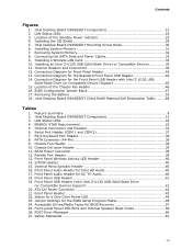
...pin to ground for at least 50 ms to signal the power supply to switch on or off. (The time requirement is a connection diagram for the Standard Front Panel USB Header 44 Table 22. Systems built with a dual-color front panel power LED can also use alternate ...through the BIOS setup. Connection Diagram for the standard front panel USB header (see Figure 11, T). States for a one - Figure 13. Table 22 shows the possible states for a One-Color Power LED LED State Off Blinking Steady Green Description Power off signal. Intel Desktop Board D945GSEJT Product Guide Power/Sleep LED ...
...pin to ground for at least 50 ms to signal the power supply to switch on or off. (The time requirement is a connection diagram for the Standard Front Panel USB Header 44 Table 22. Systems built with a dual-color front panel power LED can also use alternate ...through the BIOS setup. Connection Diagram for the standard front panel USB header (see Figure 11, T). States for a one - Figure 13. Table 22 shows the possible states for a One-Color Power LED LED State Off Blinking Steady Green Description Power off signal. Intel Desktop Board D945GSEJT Product Guide Power/Sleep LED ...

Product Guide
Page 45
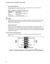
Figure 14. Installing and Replacing Desktop Board Components Figure 14 is a connection diagram for the Front Panel USB Header with Intel Z-U130 USB Solid-State Drive (or Compatible Device) Support 45 Connection Diagram for the front panel USB header (see Figure 11, W).
Figure 14. Installing and Replacing Desktop Board Components Figure 14 is a connection diagram for the Front Panel USB Header with Intel Z-U130 USB Solid-State Drive (or Compatible Device) Support 45 Connection Diagram for the front panel USB header (see Figure 11, W).


