
Product Guide
Page 2
.... Disclaimer Information in this document is provided in connection with the limits for radio noise emissions from published specifications. Desktop Board DG945GCLF may contain design defects or errors known as errata which have an ordering number and are referenced in this document... without notice. Revision History Revision Revision History -001 First release of the Intel® Desktop Board DG945GCLF Product Guide Date April 2008 If an FCC declaration of conformity marking is present on the board, the following two conditions: (1) this device may not cause harmful interference,...
.... Disclaimer Information in this document is provided in connection with the limits for radio noise emissions from published specifications. Desktop Board DG945GCLF may contain design defects or errors known as errata which have an ordering number and are referenced in this document... without notice. Revision History Revision Revision History -001 First release of the Intel® Desktop Board DG945GCLF Product Guide Date April 2008 If an FCC declaration of conformity marking is present on the board, the following two conditions: (1) this device may not cause harmful interference,...

Product Guide
Page 3
... attention to important information. Intended Audience The Product Guide is not intended for Intel® Desktop Board DG945GCLF. Intended Uses All Intel® Desktop Boards are arranged as follows: 1 Desktop Board Features: a summary of product features 2 Installing and Replacing Desktop Board Components: instructions on how to install the Desktop Board and other environments, such as Information Technology Equipment (I.T.E.) for use in personal...
... attention to important information. Intended Audience The Product Guide is not intended for Intel® Desktop Board DG945GCLF. Intended Uses All Intel® Desktop Boards are arranged as follows: 1 Desktop Board Features: a summary of product features 2 Installing and Replacing Desktop Board Components: instructions on how to install the Desktop Board and other environments, such as Information Technology Equipment (I.T.E.) for use in personal...

Product Guide
Page 4
Intel Desktop Board DG945GCLF Product Guide Terminology The table below gives descriptions to some common terms used in the product guide. Term Description GB Gigabyte (1,073,741,824 bytes) GHz Gigahertz (one billion hertz) KB Kilobyte (1024 bytes) MB Megabyte (1,048,576 bytes) Mbit Megabit (1,048,576 bits) MHz Megahertz (one million hertz) iv
Intel Desktop Board DG945GCLF Product Guide Terminology The table below gives descriptions to some common terms used in the product guide. Term Description GB Gigabyte (1,073,741,824 bytes) GHz Gigahertz (one billion hertz) KB Kilobyte (1024 bytes) MB Megabyte (1,048,576 bytes) Mbit Megabit (1,048,576 bits) MHz Megahertz (one million hertz) iv

Product Guide
Page 5
Contents 1 Desktop Board Features Desktop Board Components 10 Processor ...12 Main Memory...12 Intel® 945GC Express Chipset 13 Onboard Audio Subsystem 13 Input/Output (I/O) Controller 14 LAN Subsystem 15 LAN Subsystem Software 15 LAN Status LEDs ...Begin 21 Installation Precautions 22 Prevent Power Supply Overload 22 Observe Safety and Regulatory Requirements 22 Installing the I/O Shield 23 Installing and Removing the Desktop Board 24 Installing and Removing Memory 25 Installing DIMMs 25 Removing DIMMs 27 Connecting the IDE Cable 27 Connecting the Serial ATA (SATA) Cable 29...
Contents 1 Desktop Board Features Desktop Board Components 10 Processor ...12 Main Memory...12 Intel® 945GC Express Chipset 13 Onboard Audio Subsystem 13 Input/Output (I/O) Controller 14 LAN Subsystem 15 LAN Subsystem Software 15 LAN Status LEDs ...Begin 21 Installation Precautions 22 Prevent Power Supply Overload 22 Observe Safety and Regulatory Requirements 22 Installing the I/O Shield 23 Installing and Removing the Desktop Board 24 Installing and Removing Memory 25 Installing DIMMs 25 Removing DIMMs 27 Connecting the IDE Cable 27 Connecting the Serial ATA (SATA) Cable 29...
Product Guide
Page 6
Intel Desktop Board DG945GCLF Product Guide Connecting Power Supply Cables 33 Setting the BIOS Configuration Jumper 34 Clearing Passwords 35 Replacing the Battery 36 3 Updating the BIOS Updating the BIOS with the Intel® Express BIOS Update Utility 41 Updating the BIOS with the Iflash Memory... 45 European Union Declaration of Conformity Statement 46 Product Ecology Statements 47 Recycling Considerations 47 Lead-free 2LI/Pb-free 2LI Board 50 Restriction of Hazardous Substances (RoHS 51 European Union RoHS 51 China RoHS 51 EMC Regulations 53 Ensure Electromagnetic Compatibility (...
Intel Desktop Board DG945GCLF Product Guide Connecting Power Supply Cables 33 Setting the BIOS Configuration Jumper 34 Clearing Passwords 35 Replacing the Battery 36 3 Updating the BIOS Updating the BIOS with the Intel® Express BIOS Update Utility 41 Updating the BIOS with the Iflash Memory... 45 European Union Declaration of Conformity Statement 46 Product Ecology Statements 47 Recycling Considerations 47 Lead-free 2LI/Pb-free 2LI Board 50 Restriction of Hazardous Substances (RoHS 51 European Union RoHS 51 China RoHS 51 EMC Regulations 53 Ensure Electromagnetic Compatibility (...

Product Guide
Page 7
...Location of the Chassis Fan Header 32 13. Internal Headers 30 12. Jumper Settings for Intel High Definition Audio 31 5. Connecting a 2 x 10 or 2 x 12 Power Supply Cable 33 14. Desktop Board DG945GCLF Mounting Screw Holes 24 7. Lead-Free Second Level Interconnect Marks 50 13. EMC ...Regulations 53 15. BIOS Configuration Jumper Block 34 15. Intel Desktop Board DG945GCLF Components 10 2. Installing a DIMM 26 9. Connecting the IDE Cable 28 10. Connecting the Serial ATA Cable 29 11. Feature...
...Location of the Chassis Fan Header 32 13. Internal Headers 30 12. Jumper Settings for Intel High Definition Audio 31 5. Connecting a 2 x 10 or 2 x 12 Power Supply Cable 33 14. Desktop Board DG945GCLF Mounting Screw Holes 24 7. Lead-Free Second Level Interconnect Marks 50 13. EMC ...Regulations 53 15. BIOS Configuration Jumper Block 34 15. Intel Desktop Board DG945GCLF Components 10 2. Installing a DIMM 26 9. Connecting the IDE Cable 28 10. Connecting the Serial ATA Cable 29 11. Feature...
Product Guide
Page 9
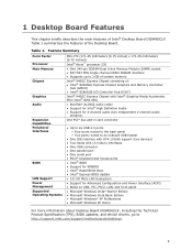
Table 1 summarizes the features of Intel® Desktop Board DG945GCLF. 1 Desktop Board Features This chapter briefly describes the main features of the Desktop Board. Table 1. Feature Summary Form Factor Processor Main Memory Chipset Graphics Audio Expansion Capabilities Peripheral ... Basic Edition • Microsoft Windows* XP Professional • Microsoft Windows XP Home For more information about Desktop Board DG945GCLF, including the Technical Product Specification (TPS), BIOS updates, and device drivers, go to http://support.intel.com/support/motherboards/desktop/. 9
Table 1 summarizes the features of Intel® Desktop Board DG945GCLF. 1 Desktop Board Features This chapter briefly describes the main features of the Desktop Board. Table 1. Feature Summary Form Factor Processor Main Memory Chipset Graphics Audio Expansion Capabilities Peripheral ... Basic Edition • Microsoft Windows* XP Professional • Microsoft Windows XP Home For more information about Desktop Board DG945GCLF, including the Technical Product Specification (TPS), BIOS updates, and device drivers, go to http://support.intel.com/support/motherboards/desktop/. 9

Product Guide
Page 10
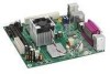
Intel Desktop Board DG945GCLF Product Guide Desktop Board Components Figure 1 shows the location of the major components on Desktop Board DG945GCLF. Intel Desktop Board DG945GCLF Components 10 Figure 1.
Intel Desktop Board DG945GCLF Product Guide Desktop Board Components Figure 1 shows the location of the major components on Desktop Board DG945GCLF. Intel Desktop Board DG945GCLF Components 10 Figure 1.

Product Guide
Page 12
... is not customer upgradeable. Main Memory NOTE To be fully compliant with all applicable Intel® SDRAM memory specifications, the board should be populated with gold-plated contacts. The processor is soldered to http://support.intel.com/support/motherboards/desktop/. 12 The Desktop Board has one 240-pin Double Data Rate 2 (DDR2) SDRAM Dual Inline Memory Module...
... is not customer upgradeable. Main Memory NOTE To be fully compliant with all applicable Intel® SDRAM memory specifications, the board should be populated with gold-plated contacts. The processor is soldered to http://support.intel.com/support/motherboards/desktop/. 12 The Desktop Board has one 240-pin Double Data Rate 2 (DDR2) SDRAM Dual Inline Memory Module...

Product Guide
Page 13
... (Intel® GMA 950). Desktop Board Features Intel® 945GC Express Chipset The Intel 945GC Express Chipset consists of the following devices: • Intel 82945GC Express Chipset Graphics and Memory Controller Hub (GMCH) • Intel 82801GB I /O paths. For more information about the Intel 945GC Express Chipset, go to http://www.intel.com/design/chipsets/express_flyer.htm. Onboard Audio Subsystem Desktop Board D945GCLF...
... (Intel® GMA 950). Desktop Board Features Intel® 945GC Express Chipset The Intel 945GC Express Chipset consists of the following devices: • Intel 82945GC Express Chipset Graphics and Memory Controller Hub (GMCH) • Intel 82801GB I /O paths. For more information about the Intel 945GC Express Chipset, go to http://www.intel.com/design/chipsets/express_flyer.htm. Onboard Audio Subsystem Desktop Board D945GCLF...

Product Guide
Page 14
Intel Desktop Board DG945GCLF Product Guide Figure 2 shows the default assignment of the back panel audio connectors. Back Panel Audio Connectors NOTE The back panel audio line out connector is designed to the following locations for more information about: • Audio drivers and utilities http://support.intel.com/support/motherboards/desktop/ • Installing a front panel audio solution...
Intel Desktop Board DG945GCLF Product Guide Figure 2 shows the default assignment of the back panel audio connectors. Back Panel Audio Connectors NOTE The back panel audio line out connector is designed to the following locations for more information about: • Audio drivers and utilities http://support.intel.com/support/motherboards/desktop/ • Installing a front panel audio solution...

Product Guide
Page 15
... State Blinking Off On (steady state) Indicates LAN activity is occurring. 10 Mbits/s data rate is selected. 100 Mbits/s data rate is operating. Desktop Board Features LAN Subsystem The LAN, based on the RealTek RTL8102EL Ethernet Controller, provides the following functions: • 10/100 Mb/s Ethernet LAN •...the back panel (see Figure 3). Figure 3. LAN Status LEDs Two LEDs are built into the RJ-45 LAN connector located on Intel's World Wide Web site at http://support.intel.com/support/motherboards/desktop. Table 3. These LEDs indicate the operating states of the LAN.
... State Blinking Off On (steady state) Indicates LAN activity is occurring. 10 Mbits/s data rate is selected. 100 Mbits/s data rate is operating. Desktop Board Features LAN Subsystem The LAN, based on the RealTek RTL8102EL Ethernet Controller, provides the following functions: • 10/100 Mb/s Ethernet LAN •...the back panel (see Figure 3). Figure 3. LAN Status LEDs Two LEDs are built into the RJ-45 LAN connector located on Intel's World Wide Web site at http://support.intel.com/support/motherboards/desktop. Table 3. These LEDs indicate the operating states of the LAN.
Product Guide
Page 16
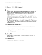
...devices such as CD-ROM or DVD drives) • Older PIO Mode devices • Ultra DMA-33/66/100 modes Serial ATA The Desktop Board supports two Serial ATA channels (3.0 Gb/s), connecting one PCI add-in the BIOS reverts all USB 2.0 ports to USB 1.1 operation. The...be required to two IDE devices (such as hard drives) • ATAPI-style devices (such as hard disks and optical drives inside the computer. Intel Desktop Board DG945GCLF Product Guide Hi-Speed USB 2.0 Support NOTE Computer systems that meets the requirements for a full-speed USB device. USB 1.1 devices will function normally...
...devices such as CD-ROM or DVD drives) • Older PIO Mode devices • Ultra DMA-33/66/100 modes Serial ATA The Desktop Board supports two Serial ATA channels (3.0 Gb/s), connecting one PCI add-in the BIOS reverts all USB 2.0 ports to USB 1.1 operation. The...be required to two IDE devices (such as hard drives) • ATAPI-style devices (such as hard disks and optical drives inside the computer. Intel Desktop Board DG945GCLF Product Guide Hi-Speed USB 2.0 Support NOTE Computer systems that meets the requirements for a full-speed USB device. USB 1.1 devices will function normally...

Product Guide
Page 17
... resetting the password, see Clearing Passwords on whether the supervisor or user password was entered. • Setting a user password restricts who can boot the computer. Desktop Board Features BIOS The BIOS provides the Power-On Self-Test (POST), the BIOS Setup program, the PCI and IDE auto-configuration utilities, and the video...
... resetting the password, see Clearing Passwords on whether the supervisor or user password was entered. • Setting a user password restricts who can boot the computer. Desktop Board Features BIOS The BIOS provides the Power-On Self-Test (POST), the BIOS Setup program, the PCI and IDE auto-configuration utilities, and the video...
Product Guide
Page 18
Intel Desktop Board DG945GCLF Product Guide Power Management Features Power management is implemented at several levels, including: • Advanced Configuration and Power Interface (ACPI) • Hardware support: ― ... power management and Plug and Play functions of the power connectors. Hardware Support Power Connectors The Desktop Board has two power connectors. See Figure 13 on page 32 for the location of a computer. Fan Headers The Desktop Board has a 3-pin MCH fan header and a 3-pin chassis fan header. See Figure 12 on page 33...
Intel Desktop Board DG945GCLF Product Guide Power Management Features Power management is implemented at several levels, including: • Advanced Configuration and Power Interface (ACPI) • Hardware support: ― ... power management and Plug and Play functions of the power connectors. Hardware Support Power Connectors The Desktop Board has two power connectors. See Figure 13 on page 32 for the location of a computer. Fan Headers The Desktop Board has a 3-pin MCH fan header and a 3-pin chassis fan header. See Figure 12 on page 33...

Product Guide
Page 19
... the power cord before installing or removing any attached devices. Location of the Standby Power Indicator For more information on the D945GCLF web page at: http://support.intel.com/support/motherboards/desktop/ 19 Desktop Board Features +5 V Standby Power Indicator LED CAUTION If the AC power has been switched off . This includes the DIMM socket and the...
... the power cord before installing or removing any attached devices. Location of the Standby Power Indicator For more information on the D945GCLF web page at: http://support.intel.com/support/motherboards/desktop/ 19 Desktop Board Features +5 V Standby Power Indicator LED CAUTION If the AC power has been switched off . This includes the DIMM socket and the...

Product Guide
Page 20
...the power supply must be capable of -day clock and 100-year calendar. Real-Time Clock The Desktop Board has a time-of delivering adequate +5 V standby current. Intel Desktop Board DG945GCLF Product Guide LAN Wake Capabilities CAUTION For LAN wake capabilities, the 5 V standby line for ...instructions on the Desktop Board keeps the clock current when the computer is turned off . LAN wakeup capabilities enable ...
...the power supply must be capable of -day clock and 100-year calendar. Real-Time Clock The Desktop Board has a time-of delivering adequate +5 V standby current. Intel Desktop Board DG945GCLF Product Guide LAN Wake Capabilities CAUTION For LAN wake capabilities, the 5 V standby line for ...instructions on the Desktop Board keeps the clock current when the computer is turned off . LAN wakeup capabilities enable ...
Product Guide
Page 21
... chassis. 21 Disconnect the computer from its power source and from any telecommunications links, networks, or modems before you begin installing the Desktop Board: • Always follow the steps in each procedure in the correct order. • Set up a log to record information about...You Begin CAUTIONS The procedures in this chapter only at an ESD workstation using and modifying electronic equipment. 2 Installing and Replacing Desktop Board Components This chapter tells you can provide some ESD protection by wearing an antistatic wrist strap and attaching it to a metal part...
... chassis. 21 Disconnect the computer from its power source and from any telecommunications links, networks, or modems before you begin installing the Desktop Board: • Always follow the steps in each procedure in the correct order. • Set up a log to record information about...You Begin CAUTIONS The procedures in this chapter only at an ESD workstation using and modifying electronic equipment. 2 Installing and Replacing Desktop Board Components This chapter tells you can provide some ESD protection by wearing an antistatic wrist strap and attaching it to a metal part...

Product Guide
Page 22
... not follow these instructions and the instructions provided by chassis and module suppliers, you install and test the Intel Desktop Board, observe all warnings and cautions in this section and the instructions supplied with regional laws and regulations. Refer to qualified technical... personnel. Intel Desktop Board DG945GCLF Product Guide Installation Precautions When you increase safety risk and the possibility of noncompliance with the chassis and ...
... not follow these instructions and the instructions provided by chassis and module suppliers, you install and test the Intel Desktop Board, observe all warnings and cautions in this section and the instructions supplied with regional laws and regulations. Refer to qualified technical... personnel. Intel Desktop Board DG945GCLF Product Guide Installation Precautions When you increase safety risk and the possibility of noncompliance with the chassis and ...

Product Guide
Page 23
Install the I/O shield before installing the Desktop Board in Figure 5. Place the shield inside the chassis as shown in the chassis. When installed in the chassis, the shield blocks radio frequency transmissions, protects .... If the shield does not fit, obtain a properly-sized shield from dust and foreign objects, and promotes correct airflow within the chassis. Installing and Replacing Desktop Board Components Installing the I/O Shield The Desktop Board comes with an I /O Shield 23 Figure 5.
Install the I/O shield before installing the Desktop Board in Figure 5. Place the shield inside the chassis as shown in the chassis. When installed in the chassis, the shield blocks radio frequency transmissions, protects .... If the shield does not fit, obtain a properly-sized shield from dust and foreign objects, and promotes correct airflow within the chassis. Installing and Replacing Desktop Board Components Installing the I/O Shield The Desktop Board comes with an I /O Shield 23 Figure 5.


