
Product Guide
Page 3
...) for Intel® Desktop Board DG945GCLF. may not be supported without further evaluation by Intel. Intended Uses All Intel® Desktop Boards are evaluated as follows: 1 Desktop Board Features: a summary of product features 2 Installing and Replacing Desktop Board Components: instructions on how to install the Desktop Board and other...are arranged as Information Technology Equipment (I.T.E.) for use in this manual: CAUTION Cautions warn the user about board layout, component installation, and regulatory requirements for installation in homes, offices, schools, computer rooms, and ...
...) for Intel® Desktop Board DG945GCLF. may not be supported without further evaluation by Intel. Intended Uses All Intel® Desktop Boards are evaluated as follows: 1 Desktop Board Features: a summary of product features 2 Installing and Replacing Desktop Board Components: instructions on how to install the Desktop Board and other...are arranged as Information Technology Equipment (I.T.E.) for use in this manual: CAUTION Cautions warn the user about board layout, component installation, and regulatory requirements for installation in homes, offices, schools, computer rooms, and ...

Product Guide
Page 5
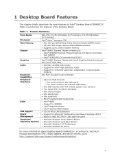
Contents 1 Desktop Board Features Desktop Board Components 10 Processor ...12 Main Memory...12 Intel® 945GC Express Chipset 13 Onboard Audio Subsystem 13 Input/Output (I/O) Controller 14 LAN Subsystem 15 LAN Subsystem Software 15 LAN Status LEDs 15 Hi-Speed USB 2.0 Support 16 Enhanced IDE Interface 16 ...Wake Capabilities 20 Wake from USB 20 Wake from PS/2 Keyboard/Mouse 20 PME# Wakeup Support 20 Battery ...20 Real-Time Clock 20 2 Installing and Replacing Desktop Board Components Before You Begin 21 Installation Precautions 22 Prevent Power Supply Overload 22 Observe Safety ...
Contents 1 Desktop Board Features Desktop Board Components 10 Processor ...12 Main Memory...12 Intel® 945GC Express Chipset 13 Onboard Audio Subsystem 13 Input/Output (I/O) Controller 14 LAN Subsystem 15 LAN Subsystem Software 15 LAN Status LEDs 15 Hi-Speed USB 2.0 Support 16 Enhanced IDE Interface 16 ...Wake Capabilities 20 Wake from USB 20 Wake from PS/2 Keyboard/Mouse 20 PME# Wakeup Support 20 Battery ...20 Real-Time Clock 20 2 Installing and Replacing Desktop Board Components Before You Begin 21 Installation Precautions 22 Prevent Power Supply Overload 22 Observe Safety ...
Product Guide
Page 9
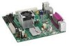
...; Microsoft Windows Vista* Starter Edition • Microsoft Windows Vista Basic Edition • Microsoft Windows* XP Professional • Microsoft Windows XP Home For more information about Desktop Board DG945GCLF, including the Technical Product Specification (TPS), BIOS updates, and device drivers, go to http://support.intel.com/support/motherboards/desktop/. 9 1 Desktop Board Features This chapter briefly describes the main features of...
...; Microsoft Windows Vista* Starter Edition • Microsoft Windows Vista Basic Edition • Microsoft Windows* XP Professional • Microsoft Windows XP Home For more information about Desktop Board DG945GCLF, including the Technical Product Specification (TPS), BIOS updates, and device drivers, go to http://support.intel.com/support/motherboards/desktop/. 9 1 Desktop Board Features This chapter briefly describes the main features of...

Product Guide
Page 12
... customer upgradeable. Main Memory NOTE To be fully compliant with all applicable Intel® SDRAM memory specifications, the board should be populated with gold-plated contacts. If your DIMMs do not support SPD, you will attempt to http://support.intel.com/support/motherboards/desktop/. 12 The Desktop Board has one 240-pin Double Data Rate 2 (DDR2) SDRAM Dual Inline Memory...
... customer upgradeable. Main Memory NOTE To be fully compliant with all applicable Intel® SDRAM memory specifications, the board should be populated with gold-plated contacts. If your DIMMs do not support SPD, you will attempt to http://support.intel.com/support/motherboards/desktop/. 12 The Desktop Board has one 240-pin Double Data Rate 2 (DDR2) SDRAM Dual Inline Memory...

Product Guide
Page 13
... ALC662 audio codec. Desktop Board Features Intel® 945GC Express Chipset The Intel 945GC Express Chipset consists of the following headers and connectors: • Front panel audio header, including functionality for the board's I /O Controller Hub (ICH7) The GMCH component provides interfaces to the processor, memory, and the DMI interconnect. Onboard Audio Subsystem Desktop Board D945GCLF has a 4-channel (two...
... ALC662 audio codec. Desktop Board Features Intel® 945GC Express Chipset The Intel 945GC Express Chipset consists of the following headers and connectors: • Front panel audio header, including functionality for the board's I /O Controller Hub (ICH7) The GMCH component provides interfaces to the processor, memory, and the DMI interconnect. Onboard Audio Subsystem Desktop Board D945GCLF has a 4-channel (two...

Product Guide
Page 14
...passive (non-amplified) speakers are connected to the following locations for more information about: • Audio drivers and utilities http://support.intel.com/support/motherboards/desktop/ • Installing a front panel audio solution (page 31) Input/Output (I/O) Controller The super I/O controller features the ... PCI power management support 14 Back Panel Audio Connectors NOTE The back panel audio line out connector is designed to power headphones or amplified speakers only. Item A B C Description Line In Line Out Mic In Figure 2. Intel Desktop Board DG945GCLF Product Guide...
...passive (non-amplified) speakers are connected to the following locations for more information about: • Audio drivers and utilities http://support.intel.com/support/motherboards/desktop/ • Installing a front panel audio solution (page 31) Input/Output (I/O) Controller The super I/O controller features the ... PCI power management support 14 Back Panel Audio Connectors NOTE The back panel audio line out connector is designed to power headphones or amplified speakers only. Item A B C Description Line In Line Out Mic In Figure 2. Intel Desktop Board DG945GCLF Product Guide...

Product Guide
Page 15
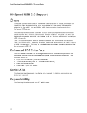
... rate is operating. Table 3. These LEDs indicate the operating states of the LAN. Desktop Board Features LAN Subsystem The LAN, based on the RealTek RTL8102EL Ethernet Controller, provides the following functions: • 10/100 Mb/s Ethernet LAN • Support for RJ-45 connector with status indicator LEDs • Programmable transit threshold • ... the DG945GCLF link on the back panel (see Figure 3). Figure 3. LAN Status LEDs Two LEDs are built into the RJ-45 LAN connector located on Intel's World Wide Web site at http://support.intel.com/support/motherboards/desktop.
... rate is operating. Table 3. These LEDs indicate the operating states of the LAN. Desktop Board Features LAN Subsystem The LAN, based on the RealTek RTL8102EL Ethernet Controller, provides the following functions: • 10/100 Mb/s Ethernet LAN • Support for RJ-45 connector with status indicator LEDs • Programmable transit threshold • ... the DG945GCLF link on the back panel (see Figure 3). Figure 3. LAN Status LEDs Two LEDs are built into the RJ-45 LAN connector located on Intel's World Wide Web site at http://support.intel.com/support/motherboards/desktop.
Product Guide
Page 16
... (such as hard disks and optical drives inside the computer. USB 1.1 devices will function normally at USB 1.1 speeds. Expandability The Desktop Board supports one device per channel. Intel Desktop Board DG945GCLF Product Guide Hi-Speed USB 2.0 Support NOTE Computer systems that have an unshielded cable attached to a USB port might not meet FCC Class B requirements, even if...
... (such as hard disks and optical drives inside the computer. USB 1.1 devices will function normally at USB 1.1 speeds. Expandability The Desktop Board supports one device per channel. Intel Desktop Board DG945GCLF Product Guide Hi-Speed USB 2.0 Support NOTE Computer systems that have an unshielded cable attached to a USB port might not meet FCC Class B requirements, even if...

Product Guide
Page 18
.... 18 See Figure 12 on page 33 for the location of the power connectors. Hardware Support Power Connectors The Desktop Board has two power connectors. Fan Headers The Desktop Board has a 3-pin MCH fan header and a 3-pin chassis fan header. Intel Desktop Board DG945GCLF Product Guide Power Management Features Power management is implemented at several levels, including: •...
.... 18 See Figure 12 on page 33 for the location of the power connectors. Hardware Support Power Connectors The Desktop Board has two power connectors. Fan Headers The Desktop Board has a 3-pin MCH fan header and a 3-pin chassis fan header. Intel Desktop Board DG945GCLF Product Guide Power Management Features Power management is implemented at several levels, including: •...

Product Guide
Page 19
...PCI bus connector, even though the computer appears to be off and the standby power indicator is standby power to the system. Desktop Board Features +5 V Standby Power Indicator LED CAUTION If the AC power has been switched off . Figure 4. Location of the ...Standby Power Indicator For more information on standby current requirements for the Desktop Board, refer to the board. Failure to do so could damage the board and any devices connected to the Technical Product Specification on the D945GCLF web page at: http://support.intel.com/support/motherboards/desktop/ 19
...PCI bus connector, even though the computer appears to be off and the standby power indicator is standby power to the system. Desktop Board Features +5 V Standby Power Indicator LED CAUTION If the AC power has been switched off . Figure 4. Location of the ...Standby Power Indicator For more information on standby current requirements for the Desktop Board, refer to the board. Failure to do so could damage the board and any devices connected to the Technical Product Specification on the D945GCLF web page at: http://support.intel.com/support/motherboards/desktop/ 19

Product Guide
Page 20
... the clock current when the computer is turned off . Intel Desktop Board DG945GCLF Product Guide LAN Wake Capabilities CAUTION For LAN wake capabilities, the 5 V standby line for instructions on how to replace the battery. Failure to page ... USB requires the use of the computer through a network. The battery on the Desktop Board keeps the values in CMOS RAM and the clock current when the computer is asserted, the computer wakes from an ACPI S1 state. PME# Wakeup Support When the PME# signal on the PCI bus is turned off . 20...
... the clock current when the computer is turned off . Intel Desktop Board DG945GCLF Product Guide LAN Wake Capabilities CAUTION For LAN wake capabilities, the 5 V standby line for instructions on how to replace the battery. Failure to page ... USB requires the use of the computer through a network. The battery on the Desktop Board keeps the values in CMOS RAM and the clock current when the computer is asserted, the computer wakes from an ACPI S1 state. PME# Wakeup Support When the PME# signal on the PCI bus is turned off . 20...

Product Guide
Page 25
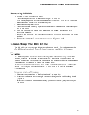
Figure 7. Installing DIMMs To make sure you have the correct DIMM, place it on the illustration in Figure 7 showing the DDR2 DIMM. The Desktop Board has one 240-pin DDR2 DIMM socket. Installing and Replacing Desktop Board Components Installing and Removing Memory NOTE To be fully compliant with all applicable Intel SDRAM memory specifications, the boards require DIMMs that support the Serial Presence Detect (SPD) data structure. Use DDR2 DIMMs 25 All the notches should match the DDR2 DIMM.
Figure 7. Installing DIMMs To make sure you have the correct DIMM, place it on the illustration in Figure 7 showing the DDR2 DIMM. The Desktop Board has one 240-pin DDR2 DIMM socket. Installing and Replacing Desktop Board Components Installing and Removing Memory NOTE To be fully compliant with all applicable Intel SDRAM memory specifications, the boards require DIMMs that support the Serial Presence Detect (SPD) data structure. Use DDR2 DIMMs 25 All the notches should match the DDR2 DIMM.
Product Guide
Page 27
...spread the retaining clips at each end of the cable. Connecting the IDE Cable The IDE cable can connect two drives to the Intel Desktop Board (Figure 9). 3. Figure 9 shows the correct installation of the DIMM socket. Turn off all peripheral devices connected to reach the ... it away from the computer. 4. The cable supports the ATA-100 transfer protocol. The DIMM pops out of the cable: 1. Observe the precautions in an anti-static package. 7. Remove the computer's cover. 5. Installing and Replacing Desktop Board Components Removing DIMMs To remove a DIMM, follow...
...spread the retaining clips at each end of the cable. Connecting the IDE Cable The IDE cable can connect two drives to the Intel Desktop Board (Figure 9). 3. Figure 9 shows the correct installation of the DIMM socket. Turn off all peripheral devices connected to reach the ... it away from the computer. 4. The cable supports the ATA-100 transfer protocol. The DIMM pops out of the cable: 1. Observe the precautions in an anti-static package. 7. Remove the computer's cover. 5. Installing and Replacing Desktop Board Components Removing DIMMs To remove a DIMM, follow...

Product Guide
Page 29
Attach the locking cable end to the connector on page 21. 2. Observe the precautions in "Before You Begin" on the board (Figure 10, A). 3. For correct cable function: 1. Connecting the Serial ATA Cable 29 Installing and Replacing Desktop Board Components Connecting the Serial ATA (SATA) Cable The SATA cable supports the Serial ATA protocol and connects a single drive to the drive (Figure 10, B). Figure 10. Attach the cable end without the lock to the desktop board.
Attach the locking cable end to the connector on page 21. 2. Observe the precautions in "Before You Begin" on the board (Figure 10, A). 3. For correct cable function: 1. Connecting the Serial ATA Cable 29 Installing and Replacing Desktop Board Components Connecting the Serial ATA (SATA) Cable The SATA cable supports the Serial ATA protocol and connects a single drive to the drive (Figure 10, B). Figure 10. Attach the cable end without the lock to the desktop board.

Product Guide
Page 41
... Utility 41 You can access the BIOS Setup program by using the Intel Express BIOS Update utility or the Iflash Memory Update utility, and how to http://support.intel.com/support/motherboards/desktop/. 2. Navigate to complete the BIOS update. Updating the BIOS with the Intel Express BIOS Update utility: 1. Follow the instructions provided in the Windows environment...
... Utility 41 You can access the BIOS Setup program by using the Intel Express BIOS Update utility or the Iflash Memory Update utility, and how to http://support.intel.com/support/motherboards/desktop/. 2. Navigate to complete the BIOS update. Updating the BIOS with the Intel Express BIOS Update utility: 1. Follow the instructions provided in the Windows environment...

Product Guide
Page 42
...BIO file and IFLASH.EXE to : http://support.intel.com/support/motherboards/desktop/ 42 For more information about recovering the BIOS for desktop board DG945GCLF, go to a bootable USB flash drive or other bootable USB media. 2. Intel Desktop Board DG945GCLF Product Guide You can obtain either of...interruption occurs, the BIOS could be extracted locally to your computer supplier or by navigating to the Desktop Board DG945GCLF page at http://support.intel.com/support/motherboards/desktop. CAUTION Do not interrupt the process or the system may not function properly. 1. Recovering the BIOS...
...BIO file and IFLASH.EXE to : http://support.intel.com/support/motherboards/desktop/ 42 For more information about recovering the BIOS for desktop board DG945GCLF, go to a bootable USB flash drive or other bootable USB media. 2. Intel Desktop Board DG945GCLF Product Guide You can obtain either of...interruption occurs, the BIOS could be extracted locally to your computer supplier or by navigating to the Desktop Board DG945GCLF page at http://support.intel.com/support/motherboards/desktop. CAUTION Do not interrupt the process or the system may not function properly. 1. Recovering the BIOS...

Product Specification
Page 3
...board A map of the resources of the board The features supported by the BIOS Setup program A description of the BIOS error messages, beep codes, and POST codes Regulatory compliance and battery disposal information Typographical Conventions This section contains information about the Desktop Board D945GCLF...symbols and abbreviations appear in this type. iii Intended Audience The TPS is specifically not intended for the Intel® Desktop Board D945GCLF. It is intended to provide detailed, technical information about the conventions used to call attention to important ...
...board A map of the resources of the board The features supported by the BIOS Setup program A description of the BIOS error messages, beep codes, and POST codes Regulatory compliance and battery disposal information Typographical Conventions This section contains information about the Desktop Board D945GCLF...symbols and abbreviations appear in this type. iii Intended Audience The TPS is specifically not intended for the Intel® Desktop Board D945GCLF. It is intended to provide detailed, technical information about the conventions used to call attention to important ...

Product Specification
Page 5
...9 1.1 Overview 10 1.1.1 Feature Summary 10 1.1.2 Board Layout 12 1.1.3 Block Diagram 14 1.2 Legacy Considerations 15 1.3 Online Support 15 1.4 Processor 15 1.5 System Memory 16 1.6 Intel® 945GC Chipset 17 1.6.1 Intel 945GC Graphics Subsystem 17 1.6.2 USB 19 1.6.3 IDE Support 20 1.7 Real-Time Clock Subsystem 21 1.8 Legacy ...27 1.11.1 Hardware Monitoring 27 1.11.2 Thermal Monitoring 28 1.12 Power Management 29 1.12.1 ACPI 29 1.12.2 Hardware Support 32 1.12.3 ENERGY STAR 36 2 Technical Reference 37 2.1 Memory Map 37 2.1.1 Addressable Memory 37 2.2 Connectors and Headers ...
...9 1.1 Overview 10 1.1.1 Feature Summary 10 1.1.2 Board Layout 12 1.1.3 Block Diagram 14 1.2 Legacy Considerations 15 1.3 Online Support 15 1.4 Processor 15 1.5 System Memory 16 1.6 Intel® 945GC Chipset 17 1.6.1 Intel 945GC Graphics Subsystem 17 1.6.2 USB 19 1.6.3 IDE Support 20 1.7 Real-Time Clock Subsystem 21 1.8 Legacy ...27 1.11.1 Hardware Monitoring 27 1.11.2 Thermal Monitoring 28 1.12 Power Management 29 1.12.1 ACPI 29 1.12.2 Hardware Support 32 1.12.3 ENERGY STAR 36 2 Technical Reference 37 2.1 Memory Map 37 2.1.1 Addressable Memory 37 2.2 Connectors and Headers ...
Product Specification
Page 6
Intel Desktop Board D945GCLF Technical Product Specification 2.5.2 Fan Header Current Capability 51 2.5.3 Add-in Board Considerations 52 2.6 Thermal Considerations 52 2.7 Reliability 54 2.8 Environmental 54 3 Overview of BIOS Features 55 3.1 Introduction 55 3.2 BIOS Flash Memory Organization 56 3.3 Resource Configuration 56 3.3.1 PCI* Autoconfiguration 56 3.4 System Management BIOS (SMBIOS 57 3.5 Legacy USB Support 58 3.6 BIOS Updates 59 3.6.1 Language Support...75 5.1.4 EMC Regulations 79 5.1.5 Product Certification Markings (Board Level 80 5.2 Battery Disposal Information 81 vi
Intel Desktop Board D945GCLF Technical Product Specification 2.5.2 Fan Header Current Capability 51 2.5.3 Add-in Board Considerations 52 2.6 Thermal Considerations 52 2.7 Reliability 54 2.8 Environmental 54 3 Overview of BIOS Features 55 3.1 Introduction 55 3.2 BIOS Flash Memory Organization 56 3.3 Resource Configuration 56 3.3.1 PCI* Autoconfiguration 56 3.4 System Management BIOS (SMBIOS 57 3.5 Legacy USB Support 58 3.6 BIOS Updates 59 3.6.1 Language Support...75 5.1.4 EMC Regulations 79 5.1.5 Product Certification Markings (Board Level 80 5.2 Battery Disposal Information 81 vi

Product Specification
Page 7
...Location of the Standby Power Indicator LED 36 Figure 7. Table 10. Feature Summary 10 Board Components Shown in Figure 1 13 Supported Memory Configurations 16 Audio Jack Retasking Support 23 LAN Connector LED States 26 Effects of Pressing the Power Switch 29 Power States ... Configuration Jumper Settings 49 Recommended Power Supply Current Values 51 Fan Header Current Capability 51 Thermal Considerations for Components 53 Desktop Board D945GCLF Environmental Specifications 54 BIOS Setup Program Menu Bar 56 BIOS Setup Program Function Keys 56 Acceptable Drives/Media Types for...
...Location of the Standby Power Indicator LED 36 Figure 7. Table 10. Feature Summary 10 Board Components Shown in Figure 1 13 Supported Memory Configurations 16 Audio Jack Retasking Support 23 LAN Connector LED States 26 Effects of Pressing the Power Switch 29 Power States ... Configuration Jumper Settings 49 Recommended Power Supply Current Values 51 Fan Header Current Capability 51 Thermal Considerations for Components 53 Desktop Board D945GCLF Environmental Specifications 54 BIOS Setup Program Menu Bar 56 BIOS Setup Program Function Keys 56 Acceptable Drives/Media Types for...


