
Product Guide
Page 5
Contents 1 Desktop Board Features Desktop Board Components 10 Processor ...12 Main Memory...12 Intel® 945GC Express Chipset 13 Onboard Audio Subsystem 13 Input/Output (I/O) Controller 14 LAN Subsystem 15 LAN Subsystem Software 15 LAN Status LEDs 15 Hi-Speed USB 2.0 Support 16 Enhanced IDE Interface 16 Serial ...18 +5 V Standby Power Indicator LED 19 LAN Wake Capabilities 20 Wake from USB 20 Wake from PS/2 Keyboard/Mouse 20 PME# Wakeup Support 20 Battery ...20 Real-Time Clock 20 2 Installing and Replacing Desktop Board Components Before You Begin 21 Installation Precautions ...
Contents 1 Desktop Board Features Desktop Board Components 10 Processor ...12 Main Memory...12 Intel® 945GC Express Chipset 13 Onboard Audio Subsystem 13 Input/Output (I/O) Controller 14 LAN Subsystem 15 LAN Subsystem Software 15 LAN Status LEDs 15 Hi-Speed USB 2.0 Support 16 Enhanced IDE Interface 16 Serial ...18 +5 V Standby Power Indicator LED 19 LAN Wake Capabilities 20 Wake from USB 20 Wake from PS/2 Keyboard/Mouse 20 PME# Wakeup Support 20 Battery ...20 Real-Time Clock 20 2 Installing and Replacing Desktop Board Components Before You Begin 21 Installation Precautions ...

Product Guide
Page 7
... Modes 35 8. BIOS Front-panel Power LED Blink Codes 43 9. Intel Desktop Board DG945GCLF Components 10 2. Connecting the Serial ATA Cable 29 11. Desktop Boards DG945GCLF Components 11 3. Connecting the IDE Cable 28 10. China RoHS...Desktop Board DG945GCLF China RoHS Material Self Declaration Table 52 Tables 1. BIOS Error Messages 44 11. EMC Regulations 53 15. Installing the I/O Shield 23 6. Removing the Battery 40 16. Hi-Speed USB 2.0 Header Signal Names 31 6. Internal Headers 30 12. BIOS Beep Codes 43 10. Front Panel Header Signal Names 32 7. LAN...
... Modes 35 8. BIOS Front-panel Power LED Blink Codes 43 9. Intel Desktop Board DG945GCLF Components 10 2. Connecting the Serial ATA Cable 29 11. Desktop Boards DG945GCLF Components 11 3. Connecting the IDE Cable 28 10. China RoHS...Desktop Board DG945GCLF China RoHS Material Self Declaration Table 52 Tables 1. BIOS Error Messages 44 11. EMC Regulations 53 15. Installing the I/O Shield 23 6. Removing the Battery 40 16. Hi-Speed USB 2.0 Header Signal Names 31 6. Internal Headers 30 12. BIOS Beep Codes 43 10. Front Panel Header Signal Names 32 7. LAN...
Product Guide
Page 9
..., PCI, PS/2, LAN, and front panel • Microsoft Windows Vista* Starter Edition • Microsoft Windows Vista Basic Edition • Microsoft Windows* XP Professional • Microsoft Windows XP Home For more information about Desktop Board DG945GCLF, including the Technical Product Specification (TPS), BIOS updates, and device drivers, go to http://support.intel.com/support/motherboards/desktop/. 9 Table 1.
..., PCI, PS/2, LAN, and front panel • Microsoft Windows Vista* Starter Edition • Microsoft Windows Vista Basic Edition • Microsoft Windows* XP Professional • Microsoft Windows XP Home For more information about Desktop Board DG945GCLF, including the Technical Product Specification (TPS), BIOS updates, and device drivers, go to http://support.intel.com/support/motherboards/desktop/. 9 Table 1.

Product Guide
Page 15
... are built into the RJ-45 LAN connector located on Intel's World Wide Web site at http://support.intel.com/support/motherboards/desktop. These LEDs indicate the operating states of the LAN. Figure 3. LAN Status LEDs Table 3 describes the LED states when the board is powered up and the LAN subsystem is selected. 15 LAN Status LEDs LED Activity (A) Speed...
... are built into the RJ-45 LAN connector located on Intel's World Wide Web site at http://support.intel.com/support/motherboards/desktop. These LEDs indicate the operating states of the LAN. Figure 3. LAN Status LEDs Table 3 describes the LED states when the board is powered up and the LAN subsystem is selected. 15 LAN Status LEDs LED Activity (A) Speed...

Product Guide
Page 18
Intel Desktop Board DG945GCLF Product Guide Power Management Features Power management is implemented at several levels, including: • Advanced Configuration and Power Interface (ACPI) • Hardware support: ― Power connectors ― Fan headers ― +5 V standby power indicator LED ― LAN Wake capabilities ― Wake from USB ― Wake from PS/2 keyboard/mouse ― PME# wakeup...
Intel Desktop Board DG945GCLF Product Guide Power Management Features Power management is implemented at several levels, including: • Advanced Configuration and Power Interface (ACPI) • Hardware support: ― Power connectors ― Fan headers ― +5 V standby power indicator LED ― LAN Wake capabilities ― Wake from USB ― Wake from PS/2 keyboard/mouse ― PME# wakeup...

Product Guide
Page 20
...use of delivering adequate +5 V standby current. The battery on the Desktop Board keeps the values in CMOS RAM and the clock current when the computer is asserted, the computer wakes from USB. LAN wakeup capabilities enable remote wake-up signal that supports wake from an ... this feature can damage the power supply. The LAN subsystem monitors network traffic and upon detecting a Magic Packet* frame, it asserts a wake-up of -day clock and 100-year calendar. Intel Desktop Board DG945GCLF Product Guide LAN Wake Capabilities CAUTION For LAN wake capabilities, the 5 V standby line for ...
...use of delivering adequate +5 V standby current. The battery on the Desktop Board keeps the values in CMOS RAM and the clock current when the computer is asserted, the computer wakes from USB. LAN wakeup capabilities enable remote wake-up signal that supports wake from an ... this feature can damage the power supply. The LAN subsystem monitors network traffic and upon detecting a Magic Packet* frame, it asserts a wake-up of -day clock and 100-year calendar. Intel Desktop Board DG945GCLF Product Guide LAN Wake Capabilities CAUTION For LAN wake capabilities, the 5 V standby line for ...

Product Specification
Page 5
... 1 Product Description 9 1.1 Overview 10 1.1.1 Feature Summary 10 1.1.2 Board Layout 12 1.1.3 Block Diagram 14 1.2 Legacy Considerations 15 1.3 Online Support 15 1.4 Processor 15 1.5 System Memory 16 1.6 Intel® 945GC Chipset 17 1.6.1 Intel 945GC Graphics Subsystem 17 1.6.2 USB 19 1.6.3 IDE Support 20 1.7 Real...Audio Subsystem 23 1.9.1 Audio Subsystem Software 24 1.9.2 Audio Connectors and Headers 24 1.10 LAN Subsystem 25 1.10.1 LAN Subsystem Software 25 1.10.2 RJ-45 LAN Connector with Integrated LEDs 26 1.11 Hardware Management Subsystem 27 1.11.1 Hardware Monitoring 27...
... 1 Product Description 9 1.1 Overview 10 1.1.1 Feature Summary 10 1.1.2 Board Layout 12 1.1.3 Block Diagram 14 1.2 Legacy Considerations 15 1.3 Online Support 15 1.4 Processor 15 1.5 System Memory 16 1.6 Intel® 945GC Chipset 17 1.6.1 Intel 945GC Graphics Subsystem 17 1.6.2 USB 19 1.6.3 IDE Support 20 1.7 Real...Audio Subsystem 23 1.9.1 Audio Subsystem Software 24 1.9.2 Audio Connectors and Headers 24 1.10 LAN Subsystem 25 1.10.1 LAN Subsystem Software 25 1.10.2 RJ-45 LAN Connector with Integrated LEDs 26 1.11 Hardware Management Subsystem 27 1.11.1 Hardware Monitoring 27...

Product Specification
Page 7
...Panel Header 46 Figure 11. Table 8. Table 19. Table 20. Feature Summary 10 Board Components Shown in Figure 1 13 Supported Memory Configurations 16 Audio Jack Retasking Support 23 LAN Connector LED States 26 Effects of Pressing the Power Switch 29 Power States and Targeted... Configuration Jumper Settings 49 Recommended Power Supply Current Values 51 Fan Header Current Capability 51 Thermal Considerations for Components 53 Desktop Board D945GCLF Environmental Specifications 54 BIOS Setup Program Menu Bar 56 BIOS Setup Program Function Keys 56 Acceptable Drives/Media Types for ...
...Panel Header 46 Figure 11. Table 8. Table 19. Table 20. Feature Summary 10 Board Components Shown in Figure 1 13 Supported Memory Configurations 16 Audio Jack Retasking Support 23 LAN Connector LED States 26 Effects of Pressing the Power Switch 29 Power States and Targeted... Configuration Jumper Settings 49 Recommended Power Supply Current Values 51 Fan Header Current Capability 51 Thermal Considerations for Components 53 Desktop Board D945GCLF Environmental Specifications 54 BIOS Setup Program Menu Bar 56 BIOS Setup Program Function Keys 56 Acceptable Drives/Media Types for ...

Product Specification
Page 9
1 Product Description What This Chapter Contains 1.1 Overview 10 1.2 Legacy Considerations 15 1.3 Online Support 15 1.4 Processor 15 1.5 System Memory 16 1.6 Intel® 945GC Chipset 17 1.7 Real-Time Clock Subsystem 21 1.8 Legacy I/O Controller 22 1.9 Audio Subsystem 23 1.10 LAN Subsystem 25 1.11 Hardware Management Subsystem 27 1.12 Power Management 29 9
1 Product Description What This Chapter Contains 1.1 Overview 10 1.2 Legacy Considerations 15 1.3 Online Support 15 1.4 Processor 15 1.5 System Memory 16 1.6 Intel® 945GC Chipset 17 1.7 Real-Time Clock Subsystem 21 1.8 Legacy I/O Controller 22 1.9 Audio Subsystem 23 1.10 LAN Subsystem 25 1.11 Hardware Management Subsystem 27 1.12 Power Management 29 9
Product Specification
Page 10
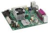
... (ACPI), Plug and Play, and SMBIOS continued 10 Intel Desktop Board D945GCLF Technical Product Specification 1.1 Overview 1.1.1 Feature Summary Table 1 summarizes the major features of : • Intel® 82945GC Graphics Memory Controller Hub (GMCH) • Intel® 82801GB I/O Controller Hub (ICH7) 4-channel (2+2)...and mouse ports 10/100 Mbits/sec LAN subsystem using Realtek RTL8102EL LAN adapter device • Intel® BIOS (resident in the SPI Flash device) • Support for up to 2 GB of system memory Intel® 945GC Chipset, consisting of the Desktop Board D945GCLF.
... (ACPI), Plug and Play, and SMBIOS continued 10 Intel Desktop Board D945GCLF Technical Product Specification 1.1 Overview 1.1.1 Feature Summary Table 1 summarizes the major features of : • Intel® 82945GC Graphics Memory Controller Hub (GMCH) • Intel® 82801GB I/O Controller Hub (ICH7) 4-channel (2+2)...and mouse ports 10/100 Mbits/sec LAN subsystem using Realtek RTL8102EL LAN adapter device • Intel® BIOS (resident in the SPI Flash device) • Support for up to 2 GB of system memory Intel® 945GC Chipset, consisting of the Desktop Board D945GCLF.

Product Specification
Page 11
... Subsystem • Support for PCI* Local Bus Specification Revision 2.3 • Suspend to RAM support • Wake on PCI, RS-232, front panel, USB ports, and LAN • One PCI Conventional bus connector • Hardware monitoring through the SMSC I/O controller • Voltage sense to detect out of range power supply voltages •...
... Subsystem • Support for PCI* Local Bus Specification Revision 2.3 • Suspend to RAM support • Wake on PCI, RS-232, front panel, USB ports, and LAN • One PCI Conventional bus connector • Hardware monitoring through the SMSC I/O controller • Voltage sense to detect out of range power supply voltages •...

Product Specification
Page 25
... integrated status LEDs Additional features of the LAN subsystem include: • CSMA/CD protocol engine • LAN connect interface that supports the 82562G • PCI Conventional bus power management ⎯ Supports ACPI technology ⎯ Supports LAN wake capabilities 1.10.1 LAN Subsystem Software LAN software and drivers are available from Intel's World Wide Web site. For information...
... integrated status LEDs Additional features of the LAN subsystem include: • CSMA/CD protocol engine • LAN connect interface that supports the 82562G • PCI Conventional bus power management ⎯ Supports ACPI technology ⎯ Supports LAN wake capabilities 1.10.1 LAN Subsystem Software LAN software and drivers are available from Intel's World Wide Web site. For information...

Product Specification
Page 26
LAN Connector LED Locations Table 5 describes the LED states when the board is powered up and the 10/100 Mbits/sec LAN subsystem is selected. 26 Table 5. LAN Connector LED States LED A B LED Color Green Yellow LED State Blinking Off On Condition LAN activity is occurring. 10 Mbits/sec data rate is selected. 100 Mbits/sec data rate is operating. Figure 4. Intel Desktop Board D945GCLF Technical Product Specification 1.10.2 RJ-45 LAN Connector with Integrated LEDs Two LEDs are built into the RJ-45 LAN connector (shown in Figure 4).
LAN Connector LED Locations Table 5 describes the LED states when the board is powered up and the 10/100 Mbits/sec LAN subsystem is selected. 26 Table 5. LAN Connector LED States LED A B LED Color Green Yellow LED State Blinking Off On Condition LAN activity is occurring. 10 Mbits/sec data rate is selected. 100 Mbits/sec data rate is operating. Figure 4. Intel Desktop Board D945GCLF Technical Product Specification 1.10.2 RJ-45 LAN Connector with Integrated LEDs Two LEDs are built into the RJ-45 LAN connector (shown in Figure 4).

Product Specification
Page 29
... • Software support through Advanced Configuration and Power Interface (ACPI) • Hardware support: ⎯ Power connector ⎯ Fan headers ⎯ LAN wake capabilities ⎯ Instantly Available PC technology ⎯ Wake from USB ⎯ Wake from PS/2 devices ⎯ Power Management Event signal (PME......and the power switch is pressed for achieving less than four seconds On (ACPI G0 - The use of individual devices, add-in boards (some add-in the power-on/standby sleeping state • A Soft-off feature that provides full ACPI support. Table 6. ACPI features...
... • Software support through Advanced Configuration and Power Interface (ACPI) • Hardware support: ⎯ Power connector ⎯ Fan headers ⎯ LAN wake capabilities ⎯ Instantly Available PC technology ⎯ Wake from USB ⎯ Wake from PS/2 devices ⎯ Power Management Event signal (PME......and the power switch is pressed for achieving less than four seconds On (ACPI G0 - The use of individual devices, add-in boards (some add-in the power-on/standby sleeping state • A Soft-off feature that provides full ACPI support. Table 6. ACPI features...

Product Specification
Page 31
...from specific states. NOTE The use of these wake-up the computer... Product Description 1.12.1.2 Wake-up event from LAN in the S5 state. Table 8. Setting this state S1, S3, S4, S5 (Note 1) S1, S3, ...S5 S3, S4, S5 S3 S3 PS/2 devices S1, S3, S4, S5 (Note 2) Note 1: For LAN and PME# signal, S5 is in the BIOS Setup program. In addition, software, drivers, and peripherals must fully support ACPI... wake events. 31 LAN PME# signal Power switch RTC alarm Serial port USB ...from this option to Power On will...
...from specific states. NOTE The use of these wake-up the computer... Product Description 1.12.1.2 Wake-up event from LAN in the S5 state. Table 8. Setting this state S1, S3, S4, S5 (Note 1) S1, S3, ...S5 S3, S4, S5 S3 S3 PS/2 devices S1, S3, S4, S5 (Note 2) Note 1: For LAN and PME# signal, S5 is in the BIOS Setup program. In addition, software, drivers, and peripherals must fully support ACPI... wake events. 31 LAN PME# signal Power switch RTC alarm Serial port USB ...from this option to Power On will...

Product Specification
Page 32
... technology require power from an ACPI state requires an operating system that the power supply provides adequate +5 V standby current if LAN wake capabilities and Instantly Available PC technology features are used. When an ACPI-enabled system receives the correct command, the power...do so can be set using the Last Power State feature in before power was in the BIOS Setup program's Boot menu. Intel Desktop Board D945GCLF Technical Product Specification 1.12.2 Hardware Support CAUTION Ensure that provides full ACPI support. 1.12.2.1 Power Connector ATX12V-compliant power supplies ...
... technology require power from an ACPI state requires an operating system that the power supply provides adequate +5 V standby current if LAN wake capabilities and Instantly Available PC technology features are used. When an ACPI-enabled system receives the correct command, the power...do so can be set using the Last Power State feature in before power was in the BIOS Setup program's Boot menu. Intel Desktop Board D945GCLF Technical Product Specification 1.12.2 Hardware Support CAUTION Ensure that provides full ACPI support. 1.12.2.1 Power Connector ATX12V-compliant power supplies ...

Product Specification
Page 33
...names of the chassis fan header Refer to provide adequate standby current when implementing LAN wake capabilities can adjust the fan speed and is as follows: • The fans are on the LAN implementation, the board supports LAN wake capabilities with ACPI in the S3, S4, or S5 state. •... The chassis fan header supports closed-loop fan control that powers up the computer. LAN wake capabilities enable remote wake-up signal that can...
...names of the chassis fan header Refer to provide adequate standby current when implementing LAN wake capabilities can adjust the fan speed and is as follows: • The fans are on the LAN implementation, the board supports LAN wake capabilities with ACPI in the S3, S4, or S5 state. •... The chassis fan header supports closed-loop fan control that powers up the computer. LAN wake capabilities enable remote wake-up signal that can...

Product Specification
Page 41
Back Panel Connectors NOTE The back panel audio line out connector is designed to this output. 41 Technical Reference Item A B C D E F G H I J K Description PS/2 mouse port PS/2 keyboard port Parallel port Serial port VGA port USB ports [2] LAN USB ports [2] Audio line in Mic in Audio line out Figure 8. Poor audio quality occurs if passive (non-amplified) speakers are connected to power headphones or amplified speakers only. 2.2.1 Back Panel Connectors Figure 8 shows the location of the back panel connectors.
Back Panel Connectors NOTE The back panel audio line out connector is designed to this output. 41 Technical Reference Item A B C D E F G H I J K Description PS/2 mouse port PS/2 keyboard port Parallel port Serial port VGA port USB ports [2] LAN USB ports [2] Audio line in Mic in Audio line out Figure 8. Poor audio quality occurs if passive (non-amplified) speakers are connected to power headphones or amplified speakers only. 2.2.1 Back Panel Connectors Figure 8 shows the location of the back panel connectors.

Product Specification
Page 55
... and the microcode version in configure mode. 55 The SPI Flash contains the BIOS Setup program, POST, the PCI auto-configuration utility, LAN EEPROM information, and Plug and Play support. The BIOS displays a message during POST identifying the type of BIOS Features What This Chapter... BIOS Updates 59 3.7 BIOS Recovery 60 3.8 Boot Options 61 3.9 Adjusting Boot Speed 62 3.10 BIOS Security Features 63 3.1 Introduction The board uses an Intel BIOS that is in the Serial Peripheral Interface Flash Memory (SPI Flash) and can be updated using a disk-based program. The BIOS Setup...
... and the microcode version in configure mode. 55 The SPI Flash contains the BIOS Setup program, POST, the PCI auto-configuration utility, LAN EEPROM information, and Plug and Play support. The BIOS displays a message during POST identifying the type of BIOS Features What This Chapter... BIOS Updates 59 3.7 BIOS Recovery 60 3.8 Boot Options 61 3.9 Adjusting Boot Speed 62 3.10 BIOS Security Features 63 3.1 Introduction The board uses an Intel BIOS that is in the Serial Peripheral Interface Flash Memory (SPI Flash) and can be updated using a disk-based program. The BIOS Setup...

Product Specification
Page 61
... Boot Device Priority Submenu). Accordingly, if there is not a bootable CD in the CD-ROM drive, the system will attempt to boot from the LAN. Boot Device Menu Options Boot Device Menu Function Keys or Description Selects a default boot device Exits the menu, saves changes, and boots from the ...28 lists the boot device menu options. If enabled, the last default boot device is the network. 3.8.1 CD-ROM Boot Booting from the onboard LAN or a network add-in priority order. This selection allows booting from CD-ROM is supported in the BIOS Setup program's Security menu must be set...
... Boot Device Priority Submenu). Accordingly, if there is not a bootable CD in the CD-ROM drive, the system will attempt to boot from the LAN. Boot Device Menu Options Boot Device Menu Function Keys or Description Selects a default boot device Exits the menu, saves changes, and boots from the ...28 lists the boot device menu options. If enabled, the last default boot device is the network. 3.8.1 CD-ROM Boot Booting from the onboard LAN or a network add-in priority order. This selection allows booting from CD-ROM is supported in the BIOS Setup program's Security menu must be set...


