
Product Guide
Page 5
Contents 1 Desktop Board Features Desktop Board Components 10 Processor ...12 Main Memory...12 Intel® 945GC Express Chipset 13 Onboard Audio Subsystem 13 Input/Output (I/O) Controller 14 LAN Subsystem 15 LAN Subsystem Software 15 LAN Status LEDs 15 Hi-Speed USB ... Installing the I/O Shield 23 Installing and Removing the Desktop Board 24 Installing and Removing Memory 25 Installing DIMMs 25 Removing DIMMs 27 Connecting the IDE Cable 27 Connecting the Serial ATA (SATA) Cable 29 Connecting Internal Headers 30 Front Panel HD Audio Header 31 Connecting the Hi-Speed USB 2.0 Header...
Contents 1 Desktop Board Features Desktop Board Components 10 Processor ...12 Main Memory...12 Intel® 945GC Express Chipset 13 Onboard Audio Subsystem 13 Input/Output (I/O) Controller 14 LAN Subsystem 15 LAN Subsystem Software 15 LAN Status LEDs 15 Hi-Speed USB ... Installing the I/O Shield 23 Installing and Removing the Desktop Board 24 Installing and Removing Memory 25 Installing DIMMs 25 Removing DIMMs 27 Connecting the IDE Cable 27 Connecting the Serial ATA (SATA) Cable 29 Connecting Internal Headers 30 Front Panel HD Audio Header 31 Connecting the Hi-Speed USB 2.0 Header...

Product Guide
Page 7
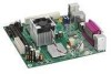
... or 2 x 12 Power Supply Cable 33 14. Front Panel Audio Header Signal Names for the BIOS Setup Program Modes 35 8. BIOS Configuration Jumper Block 34 15. Front Panel Header Signal Names 32 7. LAN Status LEDs 15 4. EMC Regulations 53 15. Contents Figures 1. Intel Desktop Board DG945GCLF Components 10 2. Installing the I/O Shield 23 6. Desktop Board DG945GCLF Mounting Screw Holes 24...
... or 2 x 12 Power Supply Cable 33 14. Front Panel Audio Header Signal Names for the BIOS Setup Program Modes 35 8. BIOS Configuration Jumper Block 34 15. Front Panel Header Signal Names 32 7. LAN Status LEDs 15 4. EMC Regulations 53 15. Contents Figures 1. Intel Desktop Board DG945GCLF Components 10 2. Installing the I/O Shield 23 6. Desktop Board DG945GCLF Mounting Screw Holes 24...
Product Guide
Page 21
...Desktop Board • Install and remove memory • Connect the IDE cable • Connect the SATA cable • Connect internal headers • Connect chassis fan and power supply cables • Set the BIOS configuration and audio... jumpers • Clear passwords • Replace the battery Before You Begin CAUTIONS The procedures in this chapter only at an ESD workstation using and modifying electronic equipment. Follow these guidelines before you begin installing the Desktop Board...Some circuitry on the board can continue to record...
...Desktop Board • Install and remove memory • Connect the IDE cable • Connect the SATA cable • Connect internal headers • Connect chassis fan and power supply cables • Set the BIOS configuration and audio... jumpers • Clear passwords • Replace the battery Before You Begin CAUTIONS The procedures in this chapter only at an ESD workstation using and modifying electronic equipment. Follow these guidelines before you begin installing the Desktop Board...Some circuitry on the board can continue to record...

Product Guide
Page 30
Intel Desktop Board DG945GCLF Product Guide Connecting Internal Headers Before connecting cables to the internal headers, observe the precautions in "Before You Begin" on page 21. Internal Headers 30 Item A B C Description Audio Hi-speed USB 2.0 Front panel Figure 11. Figure 11 shows the location of the board's internal headers.
Intel Desktop Board DG945GCLF Product Guide Connecting Internal Headers Before connecting cables to the internal headers, observe the precautions in "Before You Begin" on page 21. Internal Headers 30 Item A B C Description Audio Hi-speed USB 2.0 Front panel Figure 11. Figure 11 shows the location of the board's internal headers.

Product Guide
Page 31
... Replacing Desktop Board Components Front Panel HD Audio Header Figure 11, A shows the location of the USB 2.0 header. Table 4 shows the pin assignments for Intel High Definition Audio Pin Signal Name 1 PORT 1L 3 PORT 1R 5 PORT 2R 7 SENSE_SEND 9 PORT 2L Pin Signal Name 2 GND 4 PRESENCE# 6 SENSE1_RETURN 8 KEY (no pin) 10 SENSE2_RETURN To install a cable that connects a front panel audio...
... Replacing Desktop Board Components Front Panel HD Audio Header Figure 11, A shows the location of the USB 2.0 header. Table 4 shows the pin assignments for Intel High Definition Audio Pin Signal Name 1 PORT 1L 3 PORT 1R 5 PORT 2R 7 SENSE_SEND 9 PORT 2L Pin Signal Name 2 GND 4 PRESENCE# 6 SENSE1_RETURN 8 KEY (no pin) 10 SENSE2_RETURN To install a cable that connects a front panel audio...


