
Product Specification
Page 5
... 10 1.1.1 Feature Summary 10 1.1.2 Board Layout 12 1.1.3 Block Diagram 14 1.2 Online Support 15 1.3 Processor 15 1.4 System Memory 16 1.4.1 Memory Configurations 18 1.5 Intel® 945G Chipset 20 1.5.1 Intel 945G Graphics Subsystem 20 1.5.2 USB 22 1.5.3 IDE Support 23 1.5.4 Real-Time Clock, CMOS SRAM, ... 26 1.8.2 Audio Connectors 26 1.8.3 6-Channel (5.1) Audio Subsystem 27 1.9 LAN Subsystem 28 1.9.1 LAN Subsystem Software 28 1.9.2 Intel® 82562G Physical Layer Interface Device 28 1.10 Hardware Management Subsystem 30 1.10.1 Hardware Monitoring and Fan Control ASIC 30...
... 10 1.1.1 Feature Summary 10 1.1.2 Board Layout 12 1.1.3 Block Diagram 14 1.2 Online Support 15 1.3 Processor 15 1.4 System Memory 16 1.4.1 Memory Configurations 18 1.5 Intel® 945G Chipset 20 1.5.1 Intel 945G Graphics Subsystem 20 1.5.2 USB 22 1.5.3 IDE Support 23 1.5.4 Real-Time Clock, CMOS SRAM, ... 26 1.8.2 Audio Connectors 26 1.8.3 6-Channel (5.1) Audio Subsystem 27 1.9 LAN Subsystem 28 1.9.1 LAN Subsystem Software 28 1.9.2 Intel® 82562G Physical Layer Interface Device 28 1.10 Hardware Management Subsystem 30 1.10.1 Hardware Monitoring and Fan Control ASIC 30...
Product Specification
Page 8
BIOS Setup Program Function Keys 66 34. Boot Device Menu Options 70 35. Beep Codes 73 37. EMC Regulations 85 44. Intel Desktop Board D945GCL Technical Product Specification 15. Front Panel Audio Header 50 17. Main Power Connector 51 22. Thermal Considerations for a Two-Color Power LED ...39. Environmental Specifications 64 32. DC Loading Characteristics 59 29. BIOS Setup Program Menu Bar 66 33. Chassis Intrusion Header 50 18. Processor Fan Header 50 20. Front and Rear Chassis Fan Headers 50 21. BIOS Setup Configuration Jumper Settings 56 28...
BIOS Setup Program Function Keys 66 34. Boot Device Menu Options 70 35. Beep Codes 73 37. EMC Regulations 85 44. Intel Desktop Board D945GCL Technical Product Specification 15. Front Panel Audio Header 50 17. Main Power Connector 51 22. Thermal Considerations for a Two-Color Power LED ...39. Environmental Specifications 64 32. DC Loading Characteristics 59 29. BIOS Setup Program Menu Bar 66 33. Chassis Intrusion Header 50 18. Processor Fan Header 50 20. Front and Rear Chassis Fan Headers 50 21. BIOS Setup Configuration Jumper Settings 56 28...

Product Specification
Page 9
1 Product Description What This Chapter Contains 1.1 Overview 10 1.2 Online Support 15 1.3 Processor 15 1.4 System Memory 16 1.5 Intel® 945G Chipset 20 1.6 PCI Express* Connectors 24 1.7 Legacy I/O Controller 25 1.8 Audio Subsystem 26 1.9 LAN Subsystem 28 1.10 Hardware Management Subsystem 30 1.11 Power Management 32 9
1 Product Description What This Chapter Contains 1.1 Overview 10 1.2 Online Support 15 1.3 Processor 15 1.4 System Memory 16 1.5 Intel® 945G Chipset 20 1.6 PCI Express* Connectors 24 1.7 Legacy I/O Controller 25 1.8 Audio Subsystem 26 1.9 LAN Subsystem 28 1.10 Hardware Management Subsystem 30 1.11 Power Management 32 9
Product Specification
Page 10
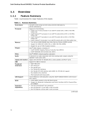
...of system memory Intel® 945G Chipset, consisting of the board. Intel Desktop Board D945GCL Technical Product Specification 1.1 Overview 1.1.1 Feature Summary Table 1 summarizes the major features of : • Intel® 82945G Graphics Memory Controller Hub (GMCH) • Intel® 82801GB I/O Controller Hub (ICH7) Intel® GMA950 ... by 243.84 millimeters]) Support for the following: • Intel® Core™2 Duo processor in an LGA775 socket with a 1066 or 800 MHz system bus • Intel® Pentium® D processor in an LGA775 socket with an 800 or 533 MHz system ...
...of system memory Intel® 945G Chipset, consisting of the board. Intel Desktop Board D945GCL Technical Product Specification 1.1 Overview 1.1.1 Feature Summary Table 1 summarizes the major features of : • Intel® 82945G Graphics Memory Controller Hub (GMCH) • Intel® 82801GB I/O Controller Hub (ICH7) Intel® GMA950 ... by 243.84 millimeters]) Support for the following: • Intel® Core™2 Duo processor in an LGA775 socket with a 1066 or 800 MHz system bus • Intel® Pentium® D processor in an LGA775 socket with an 800 or 533 MHz system ...

Product Specification
Page 13
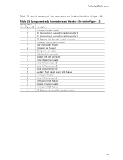
... audio header B PCI Conventional bus add-in card connectors [2] C PCI Express x16 bus add-in card connector D Back panel connectors E Processor core power connector F Rear chassis fan header G LGA775 processor socket H Intel 82945G GMCH I Processor fan header J DIMM sockets K Main Power connector L Diskette drive connector M Parallel ATE IDE connector N Battery O Front chassis fan header...
... audio header B PCI Conventional bus add-in card connectors [2] C PCI Express x16 bus add-in card connector D Back panel connectors E Processor core power connector F Rear chassis fan header G LGA775 processor socket H Intel 82945G GMCH I Processor fan header J DIMM sockets K Main Power connector L Diskette drive connector M Parallel ATE IDE connector N Battery O Front chassis fan header...
Product Specification
Page 14
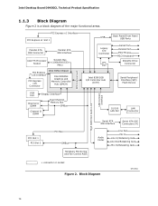
Intel Desktop Board D945GCL Technical Product Specification 1.1.3 Block Diagram Figure 2 is a block diagram of the major functional areas. Block Diagram OM18521 14 PCI Express x1 Interface PCI Express x1 Slot 1 Parallel ATA IDE Connector Parallel ATA IDE Interface LGA775 Processor Socket System Bus (1066/800/533 MHz) PCI Express x16 Interface PCI Express x16...
Intel Desktop Board D945GCL Technical Product Specification 1.1.3 Block Diagram Figure 2 is a block diagram of the major functional areas. Block Diagram OM18521 14 PCI Express x1 Interface PCI Express x1 Slot 1 Parallel ATA IDE Connector Parallel ATA IDE Interface LGA775 Processor Socket System Bus (1066/800/533 MHz) PCI Express x16 Interface PCI Express x16...
Product Specification
Page 15
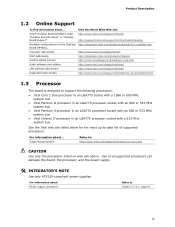
... Available configurations for the Desktop http://developer.intel.com/design/motherbd/cl/cl_available.htm Board D945GCL Processor data sheets http://www.intel.com/design/litcentr ICH7 addressing http://developer.intel.com/products/chipsets Custom splash screens http://intel.com/design/motherbd/gen_indx.htm Audio software and utilities http://www.intel.com/design/motherbd LAN software and drivers...
... Available configurations for the Desktop http://developer.intel.com/design/motherbd/cl/cl_available.htm Board D945GCL Processor data sheets http://www.intel.com/design/litcentr ICH7 addressing http://developer.intel.com/products/chipsets Custom splash screens http://intel.com/design/motherbd/gen_indx.htm Audio software and utilities http://www.intel.com/design/motherbd LAN software and drivers...

Product Specification
Page 17
Product Description NOTE Regardless of DIMMs and processors. Memory Operating Frequencies DIMM Type Processor system bus frequency DDR2 400 533 MHz DDR2 400 800 MHz DDR2 400 1066 MHz DDR2 533 533 MHz DDR2 533 800 MHz DDR2 533 ... at 533 MHz. Table 4 lists the resulting operating memory frequencies based on the combination of the DIMM type used with a 533 MHz system bus frequency processor, the memory will either be equal to or less than the...
Product Description NOTE Regardless of DIMMs and processors. Memory Operating Frequencies DIMM Type Processor system bus frequency DDR2 400 533 MHz DDR2 400 800 MHz DDR2 400 1066 MHz DDR2 533 533 MHz DDR2 533 800 MHz DDR2 533 ... at 533 MHz. Table 4 lists the resulting operating memory frequencies based on the combination of the DIMM type used with a 533 MHz system bus frequency processor, the memory will either be equal to or less than the...

Product Specification
Page 23
...; Four serial ATA IDE connectors that support one bus-mastering Parallel ATA IDE interface. In legacy mode, standard IDE I /O (PIO): processor controls data transfer. • 8237-style DMA: DMA offloads the processor, supporting transfer rates of up to 16 MB/sec. • Ultra DMA: DMA protocol on IDE bus supporting host and...
...; Four serial ATA IDE connectors that support one bus-mastering Parallel ATA IDE interface. In legacy mode, standard IDE I /O (PIO): processor controls data transfer. • 8237-style DMA: DMA offloads the processor, supporting transfer rates of up to 16 MB/sec. • Ultra DMA: DMA protocol on IDE bus supporting host and...
Product Specification
Page 30
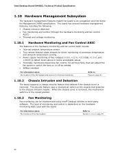
... can adjust the fan speed or switch the fans on the chassis that can be compatible with the board. Intel Desktop Board D945GCL Technical Product Specification 1.10 Hardware Management Subsystem The hardware management features enable the board to be implemented using...monitoring and fan control ASIC include: • Internal ambient temperature sensor • Two remote thermal diode sensors for direct monitoring of processor temperature and ambient temperature sensing • Power supply monitoring of the fan headers and sensors for thermal monitoring Refer to detect levels...
... can adjust the fan speed or switch the fans on the chassis that can be compatible with the board. Intel Desktop Board D945GCL Technical Product Specification 1.10 Hardware Management Subsystem The hardware management features enable the board to be implemented using...monitoring and fan control ASIC include: • Internal ambient temperature sensor • Two remote thermal diode sensors for direct monitoring of processor temperature and ambient temperature sensing • Power supply monitoring of the fan headers and sensors for thermal monitoring Refer to detect levels...

Product Specification
Page 31
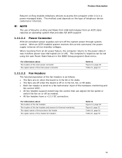
Item Description A Thermal diode, located on processor die B Ambient temperature sensor, internal to hardware monitoring and fan control ASIC C Remote ambient temperature sensor D Processor fan E Rear chassis fan F Front chassis fan Figure 9. Thermal Sensors and Fan Headers 31 Product Description 1.10.4 Thermal Monitoring Figure 9 shows the location of the sensors and fan headers.
Item Description A Thermal diode, located on processor die B Ambient temperature sensor, internal to hardware monitoring and fan control ASIC C Remote ambient temperature sensor D Processor fan E Rear chassis fan F Front chassis fan Figure 9. Thermal Sensors and Fan Headers 31 Product Description 1.10.4 Thermal Monitoring Figure 9 shows the location of the sensors and fan headers.
Product Specification
Page 33
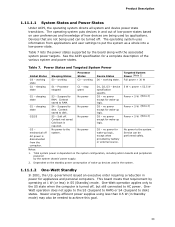
...can be performed safely. See the ACPI specification for wake-up logic. Power States and Targeted System Power Global States Sleeping States Processor States Device States Targeted System Power (Note 1) G0 - working D0 - sleeping state G2/S5 S1 - Suspend to RAM. Context not saved.... Table 7. Processor stopped C1 - S4 - D3 - D3 - No power to disk. Notes: 1. sleeping state G1 - Suspend to the system. S5 - no power ...
...can be performed safely. See the ACPI specification for wake-up logic. Power States and Targeted System Power Global States Sleeping States Processor States Device States Targeted System Power (Note 1) G0 - working D0 - sleeping state G2/S5 S1 - Suspend to RAM. Context not saved.... Table 7. Processor stopped C1 - S4 - D3 - D3 - No power to disk. Notes: 1. sleeping state G1 - Suspend to the system. S5 - no power ...
Product Specification
Page 35
.... For information about The location of the fan headers The location of the fan headers and sensors for thermal monitoring The signal names of the processor fan header The signal names of the hardware monitoring and fan control ASIC. • All fan headers support closed-loop fan control that provides full...
.... For information about The location of the fan headers The location of the fan headers and sensors for thermal monitoring The signal names of the processor fan header The signal names of the hardware monitoring and fan control ASIC. • All fan headers support closed-loop fan control that provides full...
Product Specification
Page 49
... B PCI Conventional bus add-in card connector 2 C PCI Conventional bus add-in card connector 1 D PCI Express x16 bus add-in card connector E Processor core power connector F Rear chassis fan header G Processor fan header H Main power connector I Diskette drive connector J Parallel ATA IDE connector K Front chassis fan header L Serial ATA connector 3 M Serial ATA...
... B PCI Conventional bus add-in card connector 2 C PCI Conventional bus add-in card connector 1 D PCI Express x16 bus add-in card connector E Processor core power connector F Rear chassis fan header G Processor fan header H Main power connector I Diskette drive connector J Parallel ATA IDE connector K Front chassis fan header L Serial ATA connector 3 M Serial ATA...
Product Specification
Page 50
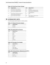
... 17. Chassis Intrusion Header Pin Signal Name 1 Intruder 2 Ground Table 18. Processor Fan Header Pin Signal Name 1 Ground 2 +12 V 3 FAN_TACH 4 FAN_CONTROL Table 20. Serial ATA Connectors Pin Signal Name 1 Ground 2 TXP 3 TXN 4 Ground 5 RXN 6 RXP 7 Ground Table 19. Intel Desktop Board D945GCL Technical Product Specification Table 16. Front Panel Audio Header Pin Signal...
... 17. Chassis Intrusion Header Pin Signal Name 1 Intruder 2 Ground Table 18. Processor Fan Header Pin Signal Name 1 Ground 2 +12 V 3 FAN_TACH 4 FAN_CONTROL Table 20. Serial ATA Connectors Pin Signal Name 1 Ground 2 TXP 3 TXN 4 Ground 5 RXN 6 RXP 7 Ground Table 19. Intel Desktop Board D945GCL Technical Product Specification Table 16. Front Panel Audio Header Pin Signal...

Product Specification
Page 51
... will prevent the board from the +12 V rail. This connector is compatible with a 2 x 12 main power cable. Failure to the processor voltage regulator and must always be unconnected. The board supports the use a power supply with 2 x 10 connectors previously used . This connector ... power directly to do so will be used on the rightmost pins of ATX12V power supplies with a 2 x 10 main power cable, attach that cable on Intel Desktop boards. Main Power Connector Pin Signal Name Pin Signal Name 1 +3.3 V 13 +3.3 V 2 +3.3 V 14 -12 V 3 Ground 15 Ground 4 +5 V...
... will prevent the board from the +12 V rail. This connector is compatible with a 2 x 12 main power cable. Failure to the processor voltage regulator and must always be unconnected. The board supports the use a power supply with 2 x 10 connectors previously used . This connector ... power directly to do so will be used on the rightmost pins of ATX12V power supplies with a 2 x 10 main power cable, attach that cable on Intel Desktop boards. Main Power Connector Pin Signal Name Pin Signal Name 1 +3.3 V 13 +3.3 V 2 +3.3 V 14 -12 V 3 Ground 15 Ground 4 +5 V...

Product Specification
Page 56
When the jumper is set to recover the BIOS configuration. A recovery diskette is powered-up, the BIOS compares the processor version and the microcode version in the BIOS and reports if the two match. The jumper block determines the BIOS Setup program's mode. ..., the board could be damaged. Always turn off the power and unplug the power cord from the computer before changing a jumper setting. Intel Desktop Board D945GCL Technical Product Specification 2.8 Jumper Block CAUTION Do not move the jumper with the power on. Figure 16 shows the location of the Jumper Block...
When the jumper is set to recover the BIOS configuration. A recovery diskette is powered-up, the BIOS compares the processor version and the microcode version in the BIOS and reports if the two match. The jumper block determines the BIOS Setup program's mode. ..., the board could be damaged. Always turn off the power and unplug the power cord from the computer before changing a jumper setting. Intel Desktop Board D945GCL Technical Product Specification 2.8 Jumper Block CAUTION Do not move the jumper with the power on. Figure 16 shows the location of the Jumper Block...
Product Specification
Page 59
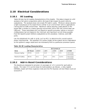
...the board that impact its power delivery subsystems. The analysis does not include PCI add-in cards, such as follows: a fully loaded D945GCL board (all active components within the board that is similar to an environment with a 500 mA current draw per USB port. Minimum values... all three expansion slots and the PCI Express x16 slot filled) must not exceed 8 A. 59 These calculations are not based on specific processor values or memory configurations but are designed to determine the overall system power requirements. The selection of the boards. Table 28. Technical Reference ...
...the board that impact its power delivery subsystems. The analysis does not include PCI add-in cards, such as follows: a fully loaded D945GCL board (all active components within the board that is similar to an environment with a 500 mA current draw per USB port. Minimum values... all three expansion slots and the PCI Express x16 slot filled) must not exceed 8 A. 59 These calculations are not based on specific processor values or memory configurations but are designed to determine the overall system power requirements. The selection of the boards. Table 28. Technical Reference ...

Product Specification
Page 60
Table 29 lists the current capability of the +5 VSB line • All timing parameters • All voltage tolerances 60 Intel Desktop Board D945GCL Technical Product Specification 2.10.3 Fan Header Current Capability CAUTION The processor fan must be capable of providing adequate +5 V standby current. Table 29. The total amount of standby current required depends on...
Table 29 lists the current capability of the +5 VSB line • All timing parameters • All voltage tolerances 60 Intel Desktop Board D945GCL Technical Product Specification 2.10.3 Fan Header Current Capability CAUTION The processor fan must be capable of providing adequate +5 V standby current. Table 29. The total amount of standby current required depends on...

Product Specification
Page 61
... temperature, see the environmental specifications in damage to the following the instructions presented in this document will result in the processor voltage regulator circuit. CAUTION Ensure that have been tested with Intel desktop boards please refer to the voltage regulator circuit. Failure to do so could cause components to 85 oC in...
... temperature, see the environmental specifications in damage to the following the instructions presented in this document will result in the processor voltage regulator circuit. CAUTION Ensure that have been tested with Intel desktop boards please refer to the voltage regulator circuit. Failure to do so could cause components to 85 oC in...


