
Product Specification
Page 5
... 26 1.7.1 Serial Port 26 1.7.2 Parallel Port 26 1.7.3 Diskette Drive Controller 26 1.7.4 Keyboard and Mouse Interface 26 1.8 Audio Subsystem 27 1.8.1 Audio Subsystem Software 27 1.8.2 Audio Connectors 27 1.8.3 6-Channel (5.1) Audio Subsystem 28 1.9 LAN Subsystem 29 1.9.1 LAN Subsystem Software 29 1.9.2 Intel® 82562G Physical Layer Interface Device 29 1.10 Hardware Management Subsystem 31 1.10.1 Hardware Monitoring and Fan...
... 26 1.7.1 Serial Port 26 1.7.2 Parallel Port 26 1.7.3 Diskette Drive Controller 26 1.7.4 Keyboard and Mouse Interface 26 1.8 Audio Subsystem 27 1.8.1 Audio Subsystem Software 27 1.8.2 Audio Connectors 27 1.8.3 6-Channel (5.1) Audio Subsystem 28 1.9 LAN Subsystem 29 1.9.1 LAN Subsystem Software 29 1.9.2 Intel® 82562G Physical Layer Interface Device 29 1.10 Hardware Management Subsystem 31 1.10.1 Hardware Monitoring and Fan...
Product Specification
Page 7
... Channel (Asymmetric) Mode Configuration with One DIMM .......... 19 6. Thermal Sensors and Fan Headers 32 10. Memory Operating Frequencies 17 5. Board Components 12 2. Front/Back Panel Audio Connector Options 28 8. LAN Connector LED Locations 30 9. Memory Channel and DIMM Configuration 18 4. Location of Conformity Statement 84 5.1.3 Product Ecology Statements 85 5.1.4 EMC Regulations...
... Channel (Asymmetric) Mode Configuration with One DIMM .......... 19 6. Thermal Sensors and Fan Headers 32 10. Memory Operating Frequencies 17 5. Board Components 12 2. Front/Back Panel Audio Connector Options 28 8. LAN Connector LED Locations 30 9. Memory Channel and DIMM Configuration 18 4. Location of Conformity Statement 84 5.1.3 Product Ecology Statements 85 5.1.4 EMC Regulations...
Product Specification
Page 8
.... BIOS Setup Program Function Keys 70 34. Supervisor and User Password Functions 76 36. Port 80h POST Code Ranges 78 39. Front Panel Audio Header 52 17. Front and Rear Chassis Fan Headers 52 21. States for Components 66 31. Beep Codes 77 37. Port 80h POST...56 26. EMC Regulations 89 44. Processor Fan Header 52 20. Lead-Free Board Markings 88 43. Product Certification Markings 90 viii Intel Desktop Board D945GCCR Technical Product Specification 15. Component-side Connectors and Headers Shown in Figure 13 51 16. Chassis Intrusion Header 52 18. Processor Core ...
.... BIOS Setup Program Function Keys 70 34. Supervisor and User Password Functions 76 36. Port 80h POST Code Ranges 78 39. Front Panel Audio Header 52 17. Front and Rear Chassis Fan Headers 52 21. States for Components 66 31. Beep Codes 77 37. Port 80h POST...56 26. EMC Regulations 89 44. Processor Fan Header 52 20. Lead-Free Board Markings 88 43. Product Certification Markings 90 viii Intel Desktop Board D945GCCR Technical Product Specification 15. Component-side Connectors and Headers Shown in Figure 13 51 16. Chassis Intrusion Header 52 18. Processor Core ...
Product Specification
Page 9
1 Product Description What This Chapter Contains 1.1 Overview 10 1.2 Online Support 15 1.3 Processor 15 1.4 System Memory 16 1.5 Intel® 945GC Chipset 21 1.6 PCI Express* Connectors 25 1.7 Legacy I/O Controller 26 1.8 Audio Subsystem 27 1.9 LAN Subsystem 29 1.10 Hardware Management Subsystem 31 1.11 Power Management 33 9
1 Product Description What This Chapter Contains 1.1 Overview 10 1.2 Online Support 15 1.3 Processor 15 1.4 System Memory 16 1.5 Intel® 945GC Chipset 21 1.6 PCI Express* Connectors 25 1.7 Legacy I/O Controller 26 1.8 Audio Subsystem 27 1.9 LAN Subsystem 29 1.10 Hardware Management Subsystem 31 1.11 Power Management 33 9
Product Specification
Page 10
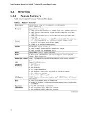
...Intel Desktop Board D945GCCR Technical Product Specification 1.1 Overview 1.1.1 Feature Summary Table 1 summarizes the major features of : • Intel® 82945GC Graphics Memory Controller Hub (GMCH) • Intel® 82801GB I/O Controller Hub (ICH7) Intel® GMA950 onboard graphics subsystem 6-channel (5.1) audio subsystem with three analog audio outputs using the Realtek* ALC883 audio...up to 4 GB of system memory Intel® 945GC Chipset, consisting of the board. Feature Summary Form Factor Processor Memory Chipset Video Audio Legacy I/O Control USB Peripheral Interfaces LAN...
...Intel Desktop Board D945GCCR Technical Product Specification 1.1 Overview 1.1.1 Feature Summary Table 1 summarizes the major features of : • Intel® 82945GC Graphics Memory Controller Hub (GMCH) • Intel® 82801GB I/O Controller Hub (ICH7) Intel® GMA950 onboard graphics subsystem 6-channel (5.1) audio subsystem with three analog audio outputs using the Realtek* ALC883 audio...up to 4 GB of system memory Intel® 945GC Chipset, consisting of the board. Feature Summary Form Factor Processor Memory Chipset Video Audio Legacy I/O Control USB Peripheral Interfaces LAN...
Product Specification
Page 13
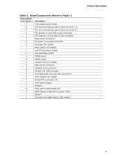
Table 2. Board Components Shown in Figure 1 Item/callout from Figure 1 Description A Front panel audio header B PCI Conventional bus add-in card connector #2 C PCI Conventional bus add-in card connector #1 D PCI Express x1 bus add-in card connector ... x16 bus add-in card connector F Back panel connectors G Processor core power connector H Processor fan header I Rear chassis fan header J LGA775 processor socket K Intel 82945GC GMCH L DIMM socket M DIMM socket N Chassis intrusion header O Main Power connector P Diskette drive connector Q Parallel ATE IDE connector...
Table 2. Board Components Shown in Figure 1 Item/callout from Figure 1 Description A Front panel audio header B PCI Conventional bus add-in card connector #2 C PCI Conventional bus add-in card connector #1 D PCI Express x1 bus add-in card connector ... x16 bus add-in card connector F Back panel connectors G Processor core power connector H Processor fan header I Rear chassis fan header J LGA775 processor socket K Intel 82945GC GMCH L DIMM socket M DIMM socket N Chassis intrusion header O Main Power connector P Diskette drive connector Q Parallel ATE IDE connector...
Product Specification
Page 15
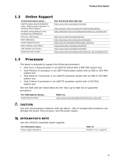
.../cr_proc.htm CAUTION Use only the processors listed on web site above. Intel® Desktop Board D945GCCR under "Desktop Board Products" or "Desktop Board Support" Available configurations for the Desktop Board D945GCCR Processor data sheets ICH7 addressing Custom splash screens Audio software and utilities LAN software and drivers Supported video modes Visit this World...
.../cr_proc.htm CAUTION Use only the processors listed on web site above. Intel® Desktop Board D945GCCR under "Desktop Board Products" or "Desktop Board Support" Available configurations for the Desktop Board D945GCCR Processor data sheets ICH7 addressing Custom splash screens Audio software and utilities LAN software and drivers Supported video modes Visit this World...

Product Specification
Page 27
...1.2, page 15 1.8.2 Audio Connectors The board contains audio connectors/headers on the Realtek ALC883 audio codec. For information about The location of the front panel audio header The signal names of 95 dB 1.8.1 Audio Subsystem Software Audio software and drivers are available from Intel's World Wide Web ..., page 52 Section 2.7.1, page 49 27 Product Description 1.8 Audio Subsystem The board supports the Intel High Definition audio subsystem based on both the back panel and the component side of the board. The audio subsystem supports the following features: • Advanced jack sense ...
...1.2, page 15 1.8.2 Audio Connectors The board contains audio connectors/headers on the Realtek ALC883 audio codec. For information about The location of the front panel audio header The signal names of 95 dB 1.8.1 Audio Subsystem Software Audio software and drivers are available from Intel's World Wide Web ..., page 52 Section 2.7.1, page 49 27 Product Description 1.8 Audio Subsystem The board supports the Intel High Definition audio subsystem based on both the back panel and the component side of the board. The audio subsystem supports the following features: • Advanced jack sense ...

Product Specification
Page 28
Intel Desktop Board D945GCCR Technical Product Specification 1.8.3 6-Channel (5.1) Audio Subsystem The 6-channel (5.1) audio subsystem includes the following: • Intel 82801GB I/O Controller Hub (ICH7) • Realtek ALC883 audio codec • Microphone input that supports a single dynamic, condenser, or electret microphone The back panel audio connectors are shown in Figure 7. The available configurable audio ports are configurable through the audio device drivers...
Intel Desktop Board D945GCCR Technical Product Specification 1.8.3 6-Channel (5.1) Audio Subsystem The 6-channel (5.1) audio subsystem includes the following: • Intel 82801GB I/O Controller Hub (ICH7) • Realtek ALC883 audio codec • Microphone input that supports a single dynamic, condenser, or electret microphone The back panel audio connectors are shown in Figure 7. The available configurable audio ports are configurable through the audio device drivers...
Product Specification
Page 45
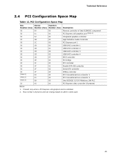
... add-in cards used. 45 PCI Configuration Space Map Bus Device Function Number (hex) Number (hex) Number (hex) Description 00 00 00 Memory controller of Intel 82945GC component 00 01 00 PCI Express x16 graphics port (Note 1) 00 02 00 Integrated graphics controller 00 1B 00 High Definition... Audio Controller 00 1C 00 PCI Express port 1 00 1D 00 USB UHCI controller 1 00 1D 01 USB UHCI controller 2 00 1D 02 USB UHCI controller 3 ...
... add-in cards used. 45 PCI Configuration Space Map Bus Device Function Number (hex) Number (hex) Number (hex) Description 00 00 00 Memory controller of Intel 82945GC component 00 01 00 PCI Express x16 graphics port (Note 1) 00 02 00 Integrated graphics controller 00 1B 00 High Definition... Audio Controller 00 1C 00 PCI Express port 1 00 1D 00 USB UHCI controller 1 00 1D 01 USB UHCI controller 2 00 1D 02 USB UHCI controller 3 ...
Product Specification
Page 49
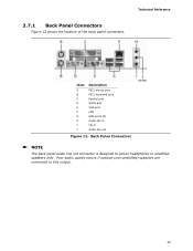
Poor audio quality occurs if passive (non-amplified) speakers are connected to power headphones or amplified speakers only. Back Panel Connectors NOTE The back panel audio line out connector is designed to this output. 49 Technical Reference 2.7.1 Back Panel Connectors Figure 12 shows the location of the back panel connectors. Item A B C D E F G H I J Description PS/2 mouse port PS/2 keyboard port Parallel port Serial port VGA port LAN USB ports [4] Audio line in Mic in Audio line out Figure 12.
Poor audio quality occurs if passive (non-amplified) speakers are connected to power headphones or amplified speakers only. Back Panel Connectors NOTE The back panel audio line out connector is designed to this output. 49 Technical Reference 2.7.1 Back Panel Connectors Figure 12 shows the location of the back panel connectors. Item A B C D E F G H I J Description PS/2 mouse port PS/2 keyboard port Parallel port Serial port VGA port LAN USB ports [4] Audio line in Mic in Audio line out Figure 12.
Product Specification
Page 51
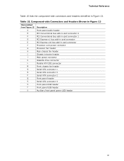
... front panel power LED header 51 Table 15. Component-side Connectors and Headers Shown in Figure 13 Item/callout from Figure 13 Description A Front panel audio header B PCI Conventional bus add-in card connector 2 C PCI Conventional bus add-in card connector 1 D PCI Express x1 bus add-in card connector E PCI Express...
... front panel power LED header 51 Table 15. Component-side Connectors and Headers Shown in Figure 13 Item/callout from Figure 13 Description A Front panel audio header B PCI Conventional bus add-in card connector 2 C PCI Conventional bus add-in card connector 1 D PCI Express x1 bus add-in card connector E PCI Express...
Product Specification
Page 52
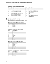
...Pin Signal Name 1 FAN_CONTROL 2 +12 V 3 FAN_TACH 52 Intel Desktop Board D945GCCR Technical Product Specification Table 16. Table 17. Processor Fan Header Pin Signal Name 1 Ground 2 +12 V 3 FAN_TACH 4 FAN_CONTROL Table 20. Front Panel Audio Header Pin Signal Name 1 Port E [Port 1] Left Channel...Port 1] Sense return (jack detection) 8 Key 10 Port F [Port 2] Sense return (jack detection) # INTEGRATOR'S NOTE The front panel audio header is colored yellow. Serial ATA Connectors Pin Signal Name 1 Ground 2 TXP 3 TXN 4 Ground 5 RXN 6 RXP 7 Ground Table ...
...Pin Signal Name 1 FAN_CONTROL 2 +12 V 3 FAN_TACH 52 Intel Desktop Board D945GCCR Technical Product Specification Table 16. Table 17. Processor Fan Header Pin Signal Name 1 Ground 2 +12 V 3 FAN_TACH 4 FAN_CONTROL Table 20. Front Panel Audio Header Pin Signal Name 1 Port E [Port 1] Left Channel...Port 1] Sense return (jack detection) 8 Key 10 Port F [Port 2] Sense return (jack detection) # INTEGRATOR'S NOTE The front panel audio header is colored yellow. Serial ATA Connectors Pin Signal Name 1 Ground 2 TXP 3 TXN 4 Ground 5 RXN 6 RXP 7 Ground Table ...
Intel Desktop Board D945GCCR Product Guide English
Page 5
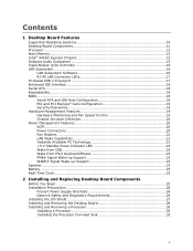
Contents 1 Desktop Board Features Supported Operating Systems 10 Desktop Board Components 11 Processor ...13 Main Memory...13 Intel® 945GC Express Chipset 15 Onboard Audio Subsystem 15 Input/Output (I/O) Controller 16 LAN Subsystem 16 LAN Subsystem Software 16 RJ-45 LAN Connector LEDs 17 Hi-Speed USB 2.0 Support 17 Enhanced ...
Contents 1 Desktop Board Features Supported Operating Systems 10 Desktop Board Components 11 Processor ...13 Main Memory...13 Intel® 945GC Express Chipset 15 Onboard Audio Subsystem 15 Input/Output (I/O) Controller 16 LAN Subsystem 16 LAN Subsystem Software 16 RJ-45 LAN Connector LEDs 17 Hi-Speed USB 2.0 Support 17 Enhanced ...
Intel Desktop Board D945GCCR Product Guide English
Page 6
Intel Desktop Board D945GCCR Product Guide Connecting the Processor Fan Heat Sink Cable 34 Removing the Processor 34 Installing and Removing Memory 35 Installing DIMMs 37 Removing DIMMs 38 ... Card 40 Connecting the IDE Cable 41 Connecting the Serial ATA (SATA) Cable 42 Connecting to Internal Headers 43 Installing a Front Panel Audio Solution for Intel® High Definition Audio 44 Connecting to the USB 2.0 Headers 45 Connecting to the Front Panel Header 45 Connecting to the Alternate Front Panel Power LED Header...
Intel Desktop Board D945GCCR Product Guide Connecting the Processor Fan Heat Sink Cable 34 Removing the Processor 34 Installing and Removing Memory 35 Installing DIMMs 37 Removing DIMMs 38 ... Card 40 Connecting the IDE Cable 41 Connecting the Serial ATA (SATA) Cable 42 Connecting to Internal Headers 43 Installing a Front Panel Audio Solution for Intel® High Definition Audio 44 Connecting to the USB 2.0 Headers 45 Connecting to the Front Panel Header 45 Connecting to the Alternate Front Panel Power LED Header...
Intel Desktop Board D945GCCR Product Guide English
Page 7
... 4. Alternate Front Panel Power LED Header 46 10. Desktop Board D945GCCR Components 11 2. Remove the Processor from the Protective Processor Cover 32 10. Jumper Settings for Intel High Definition Audio 44 6. LAN Connector LEDs 17 3. Back Panel Connectors 54 27. Front Panel Audio Header Signal Names for the BIOS Setup Program Modes 52 11...
... 4. Alternate Front Panel Power LED Header 46 10. Desktop Board D945GCCR Components 11 2. Remove the Processor from the Protective Processor Cover 32 10. Jumper Settings for Intel High Definition Audio 44 6. LAN Connector LEDs 17 3. Back Panel Connectors 54 27. Front Panel Audio Header Signal Names for the BIOS Setup Program Modes 52 11...
Intel Desktop Board D945GCCR Product Guide English
Page 9
...950) • PCI Express* graphics card support via a PCI Express x16 connector • 6-channel (5.1) onboard subsystem, featuring: ― Intel® High Definition Audio interface ― RealTek* ALC883 audio codec • One PCI Express x1 connector • One PCI Express x16 connector • Two PCI* connectors • Up to eight...8226; 533/400 MHz single or dual channel DDR2 SDRAM interface • Support for up to 2 GB of system memory Intel® 945GC Express Chipset consisting of Intel® Desktop Board D945GCCR. Table 1 summarizes the major features of the desktop board.
...950) • PCI Express* graphics card support via a PCI Express x16 connector • 6-channel (5.1) onboard subsystem, featuring: ― Intel® High Definition Audio interface ― RealTek* ALC883 audio codec • One PCI Express x1 connector • One PCI Express x16 connector • Two PCI* connectors • Up to eight...8226; 533/400 MHz single or dual channel DDR2 SDRAM interface • Support for up to 2 GB of system memory Intel® 945GC Express Chipset consisting of Intel® Desktop Board D945GCCR. Table 1 summarizes the major features of the desktop board.

Intel Desktop Board D945GCCR Product Guide English
Page 12
Intel Desktop Board D945GCCR Product Guide Table 2. Desktop Board D945GCCR Components Label A B C D E F G H I J K L M N O P Q R S T U V W X Description Front panel audio header PCI bus connector 2 PCI bus connector 1 PCI Express x1 connector PCI Express x16 connector Back panel ... Desktop Board D945GCCR • Supported processors • Audio software and utilities • LAN software and drivers http://www.intel.com/design/motherbd http://support.intel.com/support/motherboards/desktop http://www.intel.com/go/FindCPU http://www.intel.com/design/motherbd http://www.intel.com/design/...
Intel Desktop Board D945GCCR Product Guide Table 2. Desktop Board D945GCCR Components Label A B C D E F G H I J K L M N O P Q R S T U V W X Description Front panel audio header PCI bus connector 2 PCI bus connector 1 PCI Express x1 connector PCI Express x16 connector Back panel ... Desktop Board D945GCCR • Supported processors • Audio software and utilities • LAN software and drivers http://www.intel.com/design/motherbd http://support.intel.com/support/motherboards/desktop http://www.intel.com/go/FindCPU http://www.intel.com/design/motherbd http://www.intel.com/design/...

Intel Desktop Board D945GCCR Product Guide English
Page 15
... • The location of the following link for more information about the Intel 945GC Express Chipset: http://www.intel.com/products/desktop/chipsets/index.htm?iid=chips_body+desk Onboard Audio Subsystem Desktop Board D945GCCR has a flexible 6-channel (5.1) onboard audio subsystem that includes a RealTek* ALC883 audio codec. When a PCI Express x16 add-in /retasking jack Related Links...
... • The location of the following link for more information about the Intel 945GC Express Chipset: http://www.intel.com/products/desktop/chipsets/index.htm?iid=chips_body+desk Onboard Audio Subsystem Desktop Board D945GCCR has a flexible 6-channel (5.1) onboard audio subsystem that includes a RealTek* ALC883 audio codec. When a PCI Express x16 add-in /retasking jack Related Links...
Intel Desktop Board D945GCCR Product Guide English
Page 25
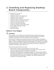
... perform any procedures can provide some ESD protection by wearing an antistatic wrist strap and attaching it to the internal headers • Connect the flexible audio system • Connect the chassis fan and power cables • Set the BIOS configuration jumper • Clear passwords • Replace the battery Before You Begin...
... perform any procedures can provide some ESD protection by wearing an antistatic wrist strap and attaching it to the internal headers • Connect the flexible audio system • Connect the chassis fan and power cables • Set the BIOS configuration jumper • Clear passwords • Replace the battery Before You Begin...


