

Product Guide
Page 3
... about connectors and desktop board resources • A Error Messages and Indicators: information about BIOS error messages and beep codes • B Regulatory Compliance: safety and EMC regulations, product certification Conventions The following conventions are used in this Product Guide are arranged as follows: • 1 Desktop Board Features: a summary of data. iii CAUTION Cautions warn the user about board layout, component installation, BIOS update, and regulatory requirements for Intel® Desktop Board D915PGN...
... about connectors and desktop board resources • A Error Messages and Indicators: information about BIOS error messages and beep codes • B Regulatory Compliance: safety and EMC regulations, product certification Conventions The following conventions are used in this Product Guide are arranged as follows: • 1 Desktop Board Features: a summary of data. iii CAUTION Cautions warn the user about board layout, component installation, BIOS update, and regulatory requirements for Intel® Desktop Board D915PGN...

Product Guide
Page 5
... Express Auto Configuration 21 Security Passwords ...22 Chassis Intrusion...22 Power Management Features 22 ACPI...22 Power Connectors ...22 Fan Connectors...23 Fan Speed Control (Intel® Precision Cooling Technology 23 Suspend to RAM (Instantly Available PC Technology 23 Resume on Ring...24 Wake from USB...24 Wake from PS/2 Keyboard/Mouse 25 PME# Wakeup Support 25 Speaker...25 Battery...25 Real-Time Clock...25 2 Installing and Replacing Desktop Board Components Before You Begin ...27 Installation Precautions ...28 Installation Instructions...28 Ensure Electromagnetic Compatibility...
... Express Auto Configuration 21 Security Passwords ...22 Chassis Intrusion...22 Power Management Features 22 ACPI...22 Power Connectors ...22 Fan Connectors...23 Fan Speed Control (Intel® Precision Cooling Technology 23 Suspend to RAM (Instantly Available PC Technology 23 Resume on Ring...24 Wake from USB...24 Wake from PS/2 Keyboard/Mouse 25 PME# Wakeup Support 25 Speaker...25 Battery...25 Real-Time Clock...25 2 Installing and Replacing Desktop Board Components Before You Begin ...27 Installation Precautions ...28 Installation Instructions...28 Ensure Electromagnetic Compatibility...

Product Guide
Page 6
... Power Supply Cables 49 Connecting 2x12 Power Supply Cables 50 Add-In Card and Peripheral Interface Connectors 51 Setting the BIOS Configuration Jumper Block 52 Clearing Passwords ...53 Back Panel Connectors...54 Replacing the Battery ...55 3 BIOS Updating the BIOS with the Intel® Express BIOS Update Utility 59 Updating the BIOS with the Iflash Memory Update Utility 59 Obtaining the BIOS Update File 59 Updating the BIOS...60 Recovering the BIOS 60 4 Desktop Board Resources Memory Map ...63 DMA Channels ...63 Interrupts...64 A Error Messages and Indicators BIOS Beep Codes...65 BIOS...
... Power Supply Cables 49 Connecting 2x12 Power Supply Cables 50 Add-In Card and Peripheral Interface Connectors 51 Setting the BIOS Configuration Jumper Block 52 Clearing Passwords ...53 Back Panel Connectors...54 Replacing the Battery ...55 3 BIOS Updating the BIOS with the Intel® Express BIOS Update Utility 59 Updating the BIOS with the Iflash Memory Update Utility 59 Obtaining the BIOS Update File 59 Updating the BIOS...60 Recovering the BIOS 60 4 Desktop Board Resources Memory Map ...63 DMA Channels ...63 Interrupts...64 A Error Messages and Indicators BIOS Beep Codes...65 BIOS...

Product Guide
Page 7
...Internal Headers ...44 22. Desktop Board D915PGN/D915PSY Memory Configurations 17 6. Contents B Regulatory Compliance Safety Regulations ...69 European Union Declaration of the PCI Bus Add-in Card and Peripheral Interface Connectors for Flexible 6-Channel Audio System 47 23. Intel Desktop Boards D915PSY and D915PCM Components 14 3. Connecting 2x12 Power Supply Cables 50 26. Manufacturing Option...11 3. Installing the I/O Shield 30 5. Removing the Battery 58 Tables 1. Feature Summary ...9 2. RJ-45 10/100 Ethernet LAN Connector LEDs 20 8. Dual Configuration...
...Internal Headers ...44 22. Desktop Board D915PGN/D915PSY Memory Configurations 17 6. Contents B Regulatory Compliance Safety Regulations ...69 European Union Declaration of the PCI Bus Add-in Card and Peripheral Interface Connectors for Flexible 6-Channel Audio System 47 23. Intel Desktop Boards D915PSY and D915PCM Components 14 3. Connecting 2x12 Power Supply Cables 50 26. Manufacturing Option...11 3. Installing the I/O Shield 30 5. Removing the Battery 58 Tables 1. Feature Summary ...9 2. RJ-45 10/100 Ethernet LAN Connector LEDs 20 8. Dual Configuration...

Product Guide
Page 10
.../2* keyboard and mouse ports BIOS • Intel/AMI BIOS • 4 Mbit symmetrical flash memory • Support for SMBIOS • Intel® Rapid BIOS Boot • Intel® Express BIOS Update Power Management • Support for Advanced Configuration and Power Interface (ACPI) • Suspend to RAM (STR) • Wake on USB, PCI, PCI Express, PS/2, LAN, and front panel Hardware Management Hardware monitor with: • Four fan sensing inputs used to monitor fan activity • Remote diode temperature sensing • Intel® Precision Cooling Technology fan speed control...
.../2* keyboard and mouse ports BIOS • Intel/AMI BIOS • 4 Mbit symmetrical flash memory • Support for SMBIOS • Intel® Rapid BIOS Boot • Intel® Express BIOS Update Power Management • Support for Advanced Configuration and Power Interface (ACPI) • Suspend to RAM (STR) • Wake on USB, PCI, PCI Express, PS/2, LAN, and front panel Hardware Management Hardware monitor with: • Four fan sensing inputs used to monitor fan activity • Remote diode temperature sensing • Intel® Precision Cooling Technology fan speed control...

Product Guide
Page 15
... D915PCM Components Description Front panel audio header PCI Express x16 connector Rear chassis fan header (fan speed control) Alternate power connector (1x4) 12 V processor core voltage connector (2x2) Processor socket Processor fan header (4-pin, controlled) Main power connector (2x12) Diskette drive connector Primary IDE connector Battery Chassis intrusion header BIOS configuration jumper Front chassis fan header (fan speed control) Power LED header Front panel header Serial ATA connectors USB 2.0 headers PCI bus add-in card connectors Speaker PCI Express x1 connector Related Links Go to...
... D915PCM Components Description Front panel audio header PCI Express x16 connector Rear chassis fan header (fan speed control) Alternate power connector (1x4) 12 V processor core voltage connector (2x2) Processor socket Processor fan header (4-pin, controlled) Main power connector (2x12) Diskette drive connector Primary IDE connector Battery Chassis intrusion header BIOS configuration jumper Front chassis fan header (fan speed control) Power LED header Front panel header Serial ATA connectors USB 2.0 headers PCI bus add-in card connectors Speaker PCI Express x1 connector Related Links Go to...

Product Guide
Page 16
Intel Desktop Board D915PGN/D915PSY/D915PCY/D915PCM Product Guide Processor CAUTION Failure to use an ATX12V power supply, or not connecting the 12 V (2x2) processor core voltage power supply connector to Desktop Board D915PGN/D915PSY/D915PCY/D915PCM may result in damage to the following links or pages for more information about: • Supported Intel® processors for Desktop Board D915PGN/D915PSY/D915PCY/D915PCM http://support.intel.com/support/motherboards/desktop/ • Instructions on the web at: http://support.intel.com/support/motherboards/desktop/ Related Links...
Intel Desktop Board D915PGN/D915PSY/D915PCY/D915PCM Product Guide Processor CAUTION Failure to use an ATX12V power supply, or not connecting the 12 V (2x2) processor core voltage power supply connector to Desktop Board D915PGN/D915PSY/D915PCY/D915PCM may result in damage to the following links or pages for more information about: • Supported Intel® processors for Desktop Board D915PGN/D915PSY/D915PCY/D915PCM http://support.intel.com/support/motherboards/desktop/ • Instructions on the web at: http://support.intel.com/support/motherboards/desktop/ Related Links...
Product Guide
Page 18
...: The audio subsystem features: • Impedance sensing capability for jack re-tasking • S/N (signal-to-noise) ratio: > 90 dB • Power management support for ACPI 2.0 (driver dependent) • Intel 82801FB I /O Controller Hub (ICH6) with gold-plated contacts. • Support for more information about: • The latest list of tested memory, http://support.intel.com/support/motherboards/desktop/ • SDRAM specifications, http://www.intel.com/technology/memory/pcsdram/spec/ • Installing memory, page...
...: The audio subsystem features: • Impedance sensing capability for jack re-tasking • S/N (signal-to-noise) ratio: > 90 dB • Power management support for ACPI 2.0 (driver dependent) • Intel 82801FB I /O Controller Hub (ICH6) with gold-plated contacts. • Support for more information about: • The latest list of tested memory, http://support.intel.com/support/motherboards/desktop/ • SDRAM specifications, http://www.intel.com/technology/memory/pcsdram/spec/ • Installing memory, page...

Product Guide
Page 19
...; Audio drivers and utilities http://support.intel.com/support/motherboards/desktop/ • Installing the front panel audio solution, page 45 in Chapter 2 • The location of audio connectors, page Figure 22 on page 47 Input/Output (I/O) Controller The super I/O controller features the following: • Low pin count (LPC) interface • One serial port • One parallel port with Extended Capabilities Port (ECP) and Enhanced Parallel Port (EPP) support • Serial IRQ interface compatible with serialized IRQ support...
...; Audio drivers and utilities http://support.intel.com/support/motherboards/desktop/ • Installing the front panel audio solution, page 45 in Chapter 2 • The location of audio connectors, page Figure 22 on page 47 Input/Output (I/O) Controller The super I/O controller features the following: • Low pin count (LPC) interface • One serial port • One parallel port with Extended Capabilities Port (ECP) and Enhanced Parallel Port (EPP) support • Serial IRQ interface compatible with serialized IRQ support...

Product Guide
Page 20
... the LED states when the board is powered up to eight USB 2.0 ports via ICH6; Yellow Off LAN link is selected. The computer is operating. Use a shielded cable that fully support USB 2.0 transfer rates. USB 2.0 ports are built into the RJ-45 LAN connector. Disabling Hi-Speed USB in the BIOS reverts all USB 2.0 ports to two internal USB 2.0 headers. Table 7. USB 1.1 devices will function normally at : http://support.intel.com/support/motherboards/desktop RJ-45 LAN Connector LEDs Two LEDs are backward compatible with...
... the LED states when the board is powered up to eight USB 2.0 ports via ICH6; Yellow Off LAN link is selected. The computer is operating. Use a shielded cable that fully support USB 2.0 transfer rates. USB 2.0 ports are built into the RJ-45 LAN connector. Disabling Hi-Speed USB in the BIOS reverts all USB 2.0 ports to two internal USB 2.0 headers. Table 7. USB 1.1 devices will function normally at : http://support.intel.com/support/motherboards/desktop RJ-45 LAN Connector LEDs Two LEDs are backward compatible with...

Product Guide
Page 21
... be updated by specifying manual configuration in card. Serial ATA and IDE Auto Configuration If you install a Serial ATA or IDE device (such as a hard drive) in your computer, the autoconfiguration utility in the BIOS automatically detects and configures the device for your computer, the PCI/PCI Express autoconfiguration utility in the BIOS automatically detects and configures the resources (IRQs, DMA channels, and I/O space) for that add-in the BIOS Setup program. Expandability The desktop boards support the following the instructions...
... be updated by specifying manual configuration in card. Serial ATA and IDE Auto Configuration If you install a Serial ATA or IDE device (such as a hard drive) in your computer, the autoconfiguration utility in the BIOS automatically detects and configures the device for your computer, the PCI/PCI Express autoconfiguration utility in the BIOS automatically detects and configures the resources (IRQs, DMA channels, and I/O space) for that add-in the BIOS Setup program. Expandability The desktop boards support the following the instructions...
Product Guide
Page 22
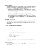
... chassis intrusion header. If only the supervisor password is booted. The password prompt is displayed before the computer is set, pressing at several levels, including: • Advanced Configuration and Power Interface (ACPI) • Hardware support: Power connectors Fan connectors Suspend to boot the computer. Setup options are set for the BIOS Setup and for the location of Setup gives the user restricted access to view and change all Setup options. Chassis Intrusion The board supports a chassis security feature that can be connected to access Setup...
... chassis intrusion header. If only the supervisor password is booted. The password prompt is displayed before the computer is set, pressing at several levels, including: • Advanced Configuration and Power Interface (ACPI) • Hardware support: Power connectors Fan connectors Suspend to boot the computer. Setup options are set for the BIOS Setup and for the location of Setup gives the user restricted access to view and change all Setup options. Chassis Intrusion The board supports a chassis security feature that can be connected to access Setup...
Product Guide
Page 23
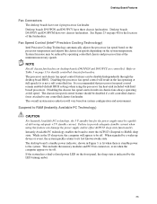
... quickly returns to -RAM) sleep state. Instantly Available PC technology enables the board to enter the ACPI S3 (Suspend-to its last known awake state. When signaled by operating controlled chassis and processor fans at full speed. The desktop board's standby power indicator, shown in the fan operating at full speed if it is indicated by the LED turning amber. 23 This includes the memory modules and PCI bus connectors, even when the...
... quickly returns to -RAM) sleep state. Instantly Available PC technology enables the board to enter the ACPI S3 (Suspend-to its last known awake state. When signaled by operating controlled chassis and processor fans at full speed. The desktop board's standby power indicator, shown in the fan operating at full speed if it is indicated by the LED turning amber. 23 This includes the memory modules and PCI bus connectors, even when the...

Product Guide
Page 27
.... 2 Installing and Replacing Desktop Board Components This chapter tells you how to: • Install the I/O shield • Install and remove the desktop board • Install and remove a processor and memory • Install and remove a x16 PCI Express card • Connect the IDE and Serial ATA cables • Connect the front panel header • Install the front panel audio and USB solutions • Connect fans and power cables • Connect PCI bus add-in and PCI Express add-in cards • Set the BIOS configuration jumper • Clear passwords • Replace the battery Before...
.... 2 Installing and Replacing Desktop Board Components This chapter tells you how to: • Install the I/O shield • Install and remove the desktop board • Install and remove a processor and memory • Install and remove a x16 PCI Express card • Connect the IDE and Serial ATA cables • Connect the front panel header • Install the front panel audio and USB solutions • Connect fans and power cables • Connect PCI bus add-in and PCI Express add-in cards • Set the BIOS configuration jumper • Clear passwords • Replace the battery Before...

Product Guide
Page 40
... electrical short may be damaged. Installing a PCI Express Card 1. Intel Desktop Board D915PGN/D915PSY/D915PCY/D915PCM Product Guide Removing DIMMs To remove a DIMM, follow these steps: 1. Observe the precautions in an anti-static package. 8. Gently spread the retaining clips at each end of the socket. 7. Reinstall the PCI Express card if you removed or disconnected to the Intel Desktop Board D915PGN/D915PSY/D915PCY/D915PCM Quick Reference). 3. Turn off all peripheral devices connected...
... electrical short may be damaged. Installing a PCI Express Card 1. Intel Desktop Board D915PGN/D915PSY/D915PCY/D915PCM Product Guide Removing DIMMs To remove a DIMM, follow these steps: 1. Observe the precautions in an anti-static package. 8. Gently spread the retaining clips at each end of the socket. 7. Reinstall the PCI Express card if you removed or disconnected to the Intel Desktop Board D915PGN/D915PSY/D915PCY/D915PCM Quick Reference). 3. Turn off all peripheral devices connected...

Product Guide
Page 52
... the jumper. Jumper Settings for the BIOS Setup Program Modes Jumper Setting 13 Mode Normal (default) (1-2) Description The BIOS uses the current configuration and passwords for the Setup program modes. Table 11 shows the jumper settings for booting. 13 13 Configure (2-3) Recovery (None) After the Power-On Self-Test (POST) runs, the BIOS displays the Maintenance Menu. The location of the desktop board's BIOS configuration jumper is shown in the event of the BIOS Configuration Jumper Block The three-pin BIOS jumper block enables all board configurations to clear passwords...
... the jumper. Jumper Settings for the BIOS Setup Program Modes Jumper Setting 13 Mode Normal (default) (1-2) Description The BIOS uses the current configuration and passwords for the Setup program modes. Table 11 shows the jumper settings for booting. 13 13 Configure (2-3) Recovery (None) After the Power-On Self-Test (POST) runs, the BIOS displays the Maintenance Menu. The location of the desktop board's BIOS configuration jumper is shown in the event of the BIOS Configuration Jumper Block The three-pin BIOS jumper block enables all board configurations to clear passwords...

Product Guide
Page 53
... computer. The computer starts the Setup program. Select Yes and press . Setup displays the maintenance menu again. 9. Press and Setup displays a pop-up screen requesting that the board is installed in the computer, and turn on page 27. 2. Replace the cover, plug in the computer and the configuration jumper block is set to the computer. Remove the computer cover. 4. Turn off the computer. Turn off all peripheral devices connected to normal mode. 1.
... computer. The computer starts the Setup program. Select Yes and press . Setup displays the maintenance menu again. 9. Press and Setup displays a pop-up screen requesting that the board is installed in the computer, and turn on page 27. 2. Replace the cover, plug in the computer and the configuration jumper block is set to the computer. Remove the computer cover. 4. Turn off the computer. Turn off all peripheral devices connected to normal mode. 1.

Product Guide
Page 59
... the Intel® Flash Memory Update Utility and the ease-of use of the BIOS by pressing the key after the Power-On Self-Test (POST) memory test begins and before the operating system boot begins. The BIOS update file is included in the Windows environment. Download the file to update the BIOS. Navigate to the Intel World Wide Web site: http://support.intel.com/support/motherboards/desktop/ 2. This step is useful if you need to your hard drive...
... the Intel® Flash Memory Update Utility and the ease-of use of the BIOS by pressing the key after the Power-On Self-Test (POST) memory test begins and before the operating system boot begins. The BIOS update file is included in the Windows environment. Download the file to update the BIOS. Navigate to the Intel World Wide Web site: http://support.intel.com/support/motherboards/desktop/ 2. This step is useful if you need to your hard drive...

Product Guide
Page 60
... screen during this procedure. Remove the computer cover and locate the configuration jumper block (see anything will automatically run the BIOS update process. 2. When the update process is complete, the monitor will not see Figure 27). 60 You will display a message telling you to: • Update the BIOS in flash memory • Update the language section of code available in drive A. NOTE Review the instructions distributed with the update files updates the BIOS...
... screen during this procedure. Remove the computer cover and locate the configuration jumper block (see anything will automatically run the BIOS update process. 2. When the update process is complete, the monitor will not see Figure 27). 60 You will display a message telling you to: • Update the BIOS in flash memory • Update the language section of code available in drive A. NOTE Review the instructions distributed with the update files updates the BIOS...

Product Guide
Page 66
... Drive - HDC Failure Checking NVRAM..... Replace the battery soon. The time and/or date values stored in CMOS are not the same as the last boot. CMOS Settings Wrong CMOS Date/Time Not Set DMA Error FDC Failure CMOS values are invalid. Update OK! ATAPI Incompatible Sec Master Drive - Intel Desktop Board D915PGN/D915PSY/D915PCY/D915PCM Product Guide BIOS Error Messages When a recoverable error occurs during the POST, the BIOS displays an error message describing the problem...
... Drive - HDC Failure Checking NVRAM..... Replace the battery soon. The time and/or date values stored in CMOS are not the same as the last boot. CMOS Settings Wrong CMOS Date/Time Not Set DMA Error FDC Failure CMOS values are invalid. Update OK! ATAPI Incompatible Sec Master Drive - Intel Desktop Board D915PGN/D915PSY/D915PCY/D915PCM Product Guide BIOS Error Messages When a recoverable error occurs during the POST, the BIOS displays an error message describing the problem...


