
Product Guide
Page 3
... to hardware or loss of product features • 2 Installing and Replacing Desktop Board Components: instructions on how to install the desktop board and other hardware components • 3 BIOS: instructions on how to important information. CAUTION Cautions warn the user about board layout, component installation, BIOS update, and regulatory requirements for Intel® Desktop Board D915PGN/D915PSY/ D915PCY/D915PCM. Intended Audience The Product Guide is not intended for technically qualified personnel. It...
... to hardware or loss of product features • 2 Installing and Replacing Desktop Board Components: instructions on how to install the desktop board and other hardware components • 3 BIOS: instructions on how to important information. CAUTION Cautions warn the user about board layout, component installation, BIOS update, and regulatory requirements for Intel® Desktop Board D915PGN/D915PSY/ D915PCY/D915PCM. Intended Audience The Product Guide is not intended for technically qualified personnel. It...

Product Guide
Page 5
... Express Auto Configuration 21 Security Passwords ...22 Chassis Intrusion...22 Power Management Features 22 ACPI...22 Power Connectors ...22 Fan Connectors...23 Fan Speed Control (Intel® Precision Cooling Technology 23 Suspend to RAM (Instantly Available PC Technology 23 Resume on Ring...24 Wake from USB...24 Wake from PS/2 Keyboard/Mouse 25 PME# Wakeup Support 25 Speaker...25 Battery...25 Real-Time Clock...25 2 Installing and Replacing Desktop Board Components Before You Begin ...27 Installation Precautions ...28 Installation Instructions...28 Ensure Electromagnetic Compatibility...
... Express Auto Configuration 21 Security Passwords ...22 Chassis Intrusion...22 Power Management Features 22 ACPI...22 Power Connectors ...22 Fan Connectors...23 Fan Speed Control (Intel® Precision Cooling Technology 23 Suspend to RAM (Instantly Available PC Technology 23 Resume on Ring...24 Wake from USB...24 Wake from PS/2 Keyboard/Mouse 25 PME# Wakeup Support 25 Speaker...25 Battery...25 Real-Time Clock...25 2 Installing and Replacing Desktop Board Components Before You Begin ...27 Installation Precautions ...28 Installation Instructions...28 Ensure Electromagnetic Compatibility...

Product Guide
Page 6
... Power Supply Cables 49 Connecting 2x12 Power Supply Cables 50 Add-In Card and Peripheral Interface Connectors 51 Setting the BIOS Configuration Jumper Block 52 Clearing Passwords ...53 Back Panel Connectors...54 Replacing the Battery ...55 3 BIOS Updating the BIOS with the Intel® Express BIOS Update Utility 59 Updating the BIOS with the Iflash Memory Update Utility 59 Obtaining the BIOS Update File 59 Updating the BIOS...60 Recovering the BIOS 60 4 Desktop Board Resources Memory Map ...63 DMA Channels ...63 Interrupts...64 A Error Messages and Indicators BIOS Beep Codes...65 BIOS...
... Power Supply Cables 49 Connecting 2x12 Power Supply Cables 50 Add-In Card and Peripheral Interface Connectors 51 Setting the BIOS Configuration Jumper Block 52 Clearing Passwords ...53 Back Panel Connectors...54 Replacing the Battery ...55 3 BIOS Updating the BIOS with the Intel® Express BIOS Update Utility 59 Updating the BIOS with the Iflash Memory Update Utility 59 Obtaining the BIOS Update File 59 Updating the BIOS...60 Recovering the BIOS 60 4 Desktop Board Resources Memory Map ...63 DMA Channels ...63 Interrupts...64 A Error Messages and Indicators BIOS Beep Codes...65 BIOS...

Product Guide
Page 7
... Fan Connector ........35 13. Connecting the Serial ATA Cable 43 21. Removing the Battery 58 Tables 1. Desktop Boards D915PGN and D915PCY Components 13 4. Desktop Boards D915PGN and D915PCY Components 12 2. Intel Desktop Boards D915PSY and D915PCM Components 14 3. Lift Socket Lever ...32 7. Connecting the IDE Cable 42 20. Connecting 2x10 Power Supply Cables 49 25. Location of Standby Power Indicator 24 4. Desktop Board D915PCY/D915PCM Memory Configurations 17 7. Remove the Processor from the Protective Cover 33 10. Removing the PCI Express x16 Card 41 19. Internal...
... Fan Connector ........35 13. Connecting the Serial ATA Cable 43 21. Removing the Battery 58 Tables 1. Desktop Boards D915PGN and D915PCY Components 13 4. Desktop Boards D915PGN and D915PCY Components 12 2. Intel Desktop Boards D915PSY and D915PCM Components 14 3. Lift Socket Lever ...32 7. Connecting the IDE Cable 42 20. Connecting 2x10 Power Supply Cables 49 25. Location of Standby Power Indicator 24 4. Desktop Board D915PCY/D915PCM Memory Configurations 17 7. Remove the Processor from the Protective Cover 33 10. Removing the PCI Express x16 Card 41 19. Internal...

Product Guide
Page 10
.../2* keyboard and mouse ports BIOS • Intel/AMI BIOS • 4 Mbit symmetrical flash memory • Support for SMBIOS • Intel® Rapid BIOS Boot • Intel® Express BIOS Update Power Management • Support for Advanced Configuration and Power Interface (ACPI) • Suspend to RAM (STR) • Wake on USB, PCI, PCI Express, PS/2, LAN, and front panel Hardware Management Hardware monitor with: • Four fan sensing inputs used to monitor fan activity • Remote diode temperature sensing • Intel® Precision Cooling Technology fan speed control...
.../2* keyboard and mouse ports BIOS • Intel/AMI BIOS • 4 Mbit symmetrical flash memory • Support for SMBIOS • Intel® Rapid BIOS Boot • Intel® Express BIOS Update Power Management • Support for Advanced Configuration and Power Interface (ACPI) • Suspend to RAM (STR) • Wake on USB, PCI, PCI Express, PS/2, LAN, and front panel Hardware Management Hardware monitor with: • Four fan sensing inputs used to monitor fan activity • Remote diode temperature sensing • Intel® Precision Cooling Technology fan speed control...

Product Guide
Page 15
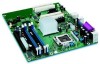
... chassis fan header (fan speed control) Alternate power connector (1x4) 12 V processor core voltage connector (2x2) Processor socket Processor fan header (4-pin, controlled) Main power connector (2x12) Diskette drive connector Primary IDE connector Battery Chassis intrusion header BIOS configuration jumper Front chassis fan header (fan speed control) Power LED header Front panel header Serial ATA connectors USB 2.0 headers PCI bus add-in card connectors Speaker PCI Express x1 connector Related Links Go to the following links for more information about: • Intel Desktop Board D915PGN...
... chassis fan header (fan speed control) Alternate power connector (1x4) 12 V processor core voltage connector (2x2) Processor socket Processor fan header (4-pin, controlled) Main power connector (2x12) Diskette drive connector Primary IDE connector Battery Chassis intrusion header BIOS configuration jumper Front chassis fan header (fan speed control) Power LED header Front panel header Serial ATA connectors USB 2.0 headers PCI bus add-in card connectors Speaker PCI Express x1 connector Related Links Go to the following links for more information about: • Intel Desktop Board D915PGN...

Product Guide
Page 16
... processors list for Desktop Boards D915PGN, D915PSY, D915PCY, and D915PCM is located on installing or upgrading the processor, page 32 in Chapter 2 • The location of the two power connectors, page 48 in Chapter 2 16 Desktop Boards D915PGN, D915PSY, D915PCY, and D915PCM support a single Intel Pentium 4 processor in damage to the desktop board and/or power supply. Intel Desktop Board D915PGN/D915PSY/D915PCY/D915PCM Product Guide Processor CAUTION Failure to use an ATX12V power supply, or not connecting the 12 V (2x2) processor core voltage power supply connector to Desktop Board...
... processors list for Desktop Boards D915PGN, D915PSY, D915PCY, and D915PCM is located on installing or upgrading the processor, page 32 in Chapter 2 • The location of the two power connectors, page 48 in Chapter 2 16 Desktop Boards D915PGN, D915PSY, D915PCY, and D915PCM support a single Intel Pentium 4 processor in damage to the desktop board and/or power supply. Intel Desktop Board D915PGN/D915PSY/D915PCY/D915PCM Product Guide Processor CAUTION Failure to use an ATX12V power supply, or not connecting the 12 V (2x2) processor core voltage power supply connector to Desktop Board...
Product Guide
Page 18
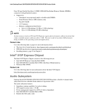
... Express Chipset The Intel 915P Express Chipset consists of memory being available to -noise) ratio: > 90 dB • Power management support for ACPI 2.0 (driver dependent) • Intel 82801FB I /O Controller Hub (ICH6) with gold-plated contacts. • Support for jack re-tasking • S/N (signal-to the operating system and applications. Intel Desktop Board D915PGN/D915PSY/D915PCY/D915PCM Product Guide Four 240-pin Double Data Rate 2 (DDR2) SDRAM Dual Inline Memory Module (DIMMs) connectors...
... Express Chipset The Intel 915P Express Chipset consists of memory being available to -noise) ratio: > 90 dB • Power management support for ACPI 2.0 (driver dependent) • Intel 82801FB I /O Controller Hub (ICH6) with gold-plated contacts. • Support for jack re-tasking • S/N (signal-to the operating system and applications. Intel Desktop Board D915PGN/D915PSY/D915PCY/D915PCM Product Guide Four 240-pin Double Data Rate 2 (DDR2) SDRAM Dual Inline Memory Module (DIMMs) connectors...

Product Guide
Page 19
...; Audio drivers and utilities http://support.intel.com/support/motherboards/desktop/ • Installing the front panel audio solution, page 45 in Chapter 2 • The location of audio connectors, page Figure 22 on page 47 Input/Output (I/O) Controller The super I/O controller features the following: • Low pin count (LPC) interface • One serial port • One parallel port with Extended Capabilities Port (ECP) and Enhanced Parallel Port (EPP) support • Serial IRQ interface compatible with serialized IRQ support...
...; Audio drivers and utilities http://support.intel.com/support/motherboards/desktop/ • Installing the front panel audio solution, page 45 in Chapter 2 • The location of audio connectors, page Figure 22 on page 47 Input/Output (I/O) Controller The super I/O controller features the following: • Low pin count (LPC) interface • One serial port • One parallel port with Extended Capabilities Port (ECP) and Enhanced Parallel Port (EPP) support • Serial IRQ interface compatible with serialized IRQ support...

Product Guide
Page 20
... cable. The interface supports: • Up to USB 1.1 operation. Hi-Speed USB 2.0 Support NOTE Computer systems that fully support USB 2.0 transfer rates. Use a shielded cable that do not support USB 2.0. The desktop board supports up and the 10/100 Ethernet LAN subsystem is powered up to eight USB 2.0 ports via ICH6; Disabling Hi-Speed USB in the BIOS reverts all USB 2.0 ports to two IDE devices (such as hard drives) • ATAPI-style devices (such as CD-ROM drives) • Older PIO Mode devices...
... cable. The interface supports: • Up to USB 1.1 operation. Hi-Speed USB 2.0 Support NOTE Computer systems that fully support USB 2.0 transfer rates. Use a shielded cable that do not support USB 2.0. The desktop board supports up and the 10/100 Ethernet LAN subsystem is powered up to eight USB 2.0 ports via ICH6; Disabling Hi-Speed USB in the BIOS reverts all USB 2.0 ports to two IDE devices (such as hard drives) • ATAPI-style devices (such as CD-ROM drives) • Older PIO Mode devices...

Product Guide
Page 21
... information about installing a PCI Express card, see page 40 in Chapter 3. Desktop Board Features Serial ATA The desktop board supports four Serial ATA channels via the ICH6, connecting one device per channel. You do not need to run the BIOS Setup program after installing a Serial ATA or IDE device. BIOS The BIOS provides the Power-On Self-Test (POST), the BIOS Setup program, the PCI/PCI Express and IDE auto-configuration utilities, and the video BIOS. You can be updated by specifying manual configuration in the Firmware Hub. The BIOS is...
... information about installing a PCI Express card, see page 40 in Chapter 3. Desktop Board Features Serial ATA The desktop board supports four Serial ATA channels via the ICH6, connecting one device per channel. You do not need to run the BIOS Setup program after installing a Serial ATA or IDE device. BIOS The BIOS provides the Power-On Self-Test (POST), the BIOS Setup program, the PCI/PCI Express and IDE auto-configuration utilities, and the video BIOS. You can be updated by specifying manual configuration in the Firmware Hub. The BIOS is...
Product Guide
Page 22
... Configuration and Power Interface (ACPI) • Hardware support: Power connectors Fan connectors Suspend to the chassis intrusion header on Ring Wake from USB Wake from PS/2 keyboard/mouse PME# wakeup support ACPI ACPI gives the operating system direct control over the power management and Plug and Play functions of ACPI with the following restrictions: • The supervisor password gives unrestricted access to boot the computer. Power Connectors The desktop board has three power connectors. Intel Desktop Board D915PGN/D915PSY/D915PCY/D915PCM Product Guide Security Passwords The BIOS...
... Configuration and Power Interface (ACPI) • Hardware support: Power connectors Fan connectors Suspend to the chassis intrusion header on Ring Wake from USB Wake from PS/2 keyboard/mouse PME# wakeup support ACPI ACPI gives the operating system direct control over the power management and Plug and Play functions of ACPI with the following restrictions: • The supervisor password gives unrestricted access to boot the computer. Power Connectors The desktop board has three power connectors. Intel Desktop Board D915PGN/D915PSY/D915PCY/D915PCM Product Guide Security Passwords The BIOS...
Product Guide
Page 23
... Intel boxed processors. This includes the memory modules and PCI bus connectors, even when the computer appears to identify controlled chassis fan headers. If the system has a dual-colored power LED on page 48 for the power supply must be capable of the fan headers. NOTE Not all chassis fan headers on page 13 to be disabled independently through the desktop board BIOS. The chassis fan speed control feature should be disabled if a self-controlled chassis fan is recommended that processor fan speed control remain enabled (default BIOS setting) when using...
... Intel boxed processors. This includes the memory modules and PCI bus connectors, even when the computer appears to identify controlled chassis fan headers. If the system has a dual-colored power LED on page 48 for the power supply must be capable of the fan headers. NOTE Not all chassis fan headers on page 13 to be disabled independently through the desktop board BIOS. The chassis fan speed control feature should be disabled if a self-controlled chassis fan is recommended that processor fan speed control remain enabled (default BIOS setting) when using...

Product Guide
Page 27
... wrist strap and attaching it to : • Install the I/O shield • Install and remove the desktop board • Install and remove a processor and memory • Install and remove a x16 PCI Express card • Connect the IDE and Serial ATA cables • Connect the front panel header • Install the front panel audio and USB solutions • Connect fans and power cables • Connect PCI bus add-in and PCI Express add-in cards • Set the BIOS configuration jumper • Clear passwords • Replace the battery Before You Begin WARNINGS The procedures in...
... wrist strap and attaching it to : • Install the I/O shield • Install and remove the desktop board • Install and remove a processor and memory • Install and remove a x16 PCI Express card • Connect the IDE and Serial ATA cables • Connect the front panel header • Install the front panel audio and USB solutions • Connect fans and power cables • Connect PCI bus add-in and PCI Express add-in cards • Set the BIOS configuration jumper • Clear passwords • Replace the battery Before You Begin WARNINGS The procedures in...

Product Guide
Page 40
... Guide Removing DIMMs To remove a DIMM, follow these steps: 1. Turn off all peripheral devices connected to the Intel Desktop Board D915PGN/D915PSY/D915PCY/D915PCM Quick Reference). 3. Installing and Removing a PCI Express x16 Card CAUTION When installing any parts you power on the over-current protection of the power supply, certain board components and/or traces may result across the PCI Express connector pins. Gently spread the retaining clips at each end of the socket. 7. If the card...
... Guide Removing DIMMs To remove a DIMM, follow these steps: 1. Turn off all peripheral devices connected to the Intel Desktop Board D915PGN/D915PSY/D915PCY/D915PCM Quick Reference). 3. Installing and Removing a PCI Express x16 Card CAUTION When installing any parts you power on the over-current protection of the power supply, certain board components and/or traces may result across the PCI Express connector pins. Gently spread the retaining clips at each end of the socket. 7. If the card...

Product Guide
Page 52
... shows the jumper settings for booting. 13 13 Configure (2-3) Recovery (None) After the Power-On Self-Test (POST) runs, the BIOS displays the Maintenance Menu. Table 11. Jumper Settings for the BIOS Setup Program Modes Jumper Setting 13 Mode Normal (default) (1-2) Description The BIOS uses the current configuration and passwords for the Setup program modes. The BIOS recovers data from the computer before changing the jumper. The location of a failed BIOS update. 52 Intel Desktop Board D915PGN/D915PSY/D915PCY/D915PCM Product Guide Setting the BIOS Configuration Jumper Block...
... shows the jumper settings for booting. 13 13 Configure (2-3) Recovery (None) After the Power-On Self-Test (POST) runs, the BIOS displays the Maintenance Menu. Table 11. Jumper Settings for the BIOS Setup Program Modes Jumper Setting 13 Mode Normal (default) (1-2) Description The BIOS uses the current configuration and passwords for the Setup program modes. The BIOS recovers data from the computer before changing the jumper. The location of a failed BIOS update. 52 Intel Desktop Board D915PGN/D915PSY/D915PCY/D915PCM Product Guide Setting the BIOS Configuration Jumper Block...

Product Guide
Page 53
.... Use the arrow keys to the computer. Remove the computer cover. 4. Replace the cover, plug in "Before You Begin" on pins 1-2 as shown below . 13 13. Turn off all peripheral devices connected to select Clear Passwords. Press to normal mode. 1. Replace the cover, plug in the computer and the configuration jumper block is installed in the computer, and turn on the computer, and allow it to boot. 7. Installing and Replacing Desktop Board Components Clearing Passwords...
.... Use the arrow keys to the computer. Remove the computer cover. 4. Replace the cover, plug in "Before You Begin" on pins 1-2 as shown below . 13 13. Turn off all peripheral devices connected to select Clear Passwords. Press to normal mode. 1. Replace the cover, plug in the computer and the configuration jumper block is installed in the computer, and turn on the computer, and allow it to boot. 7. Installing and Replacing Desktop Board Components Clearing Passwords...

Product Guide
Page 59
...The utility available from a floppy disk or other applications. The BIOS update file is useful if you can update the system BIOS from the Web provides a simple method for multiple identical systems.) 4. 3 BIOS The BIOS Setup program can be rebooted at the last Express BIOS Update window. 5. Navigate to the Intel World Wide Web site: http://support.intel.com/support/motherboards/desktop/ 2. Updating the BIOS with the Intel Express BIOS Update utility: 1. The BIOS update file contains: • New BIOS files • BIOS recovery files • Intel Flash Memory Update Utility...
...The utility available from a floppy disk or other applications. The BIOS update file is useful if you can update the system BIOS from the Web provides a simple method for multiple identical systems.) 4. 3 BIOS The BIOS Setup program can be rebooted at the last Express BIOS Update window. 5. Navigate to the Intel World Wide Web site: http://support.intel.com/support/motherboards/desktop/ 2. Updating the BIOS with the Intel Express BIOS Update utility: 1. The BIOS update file contains: • New BIOS files • BIOS recovery files • Intel Flash Memory Update Utility...

Product Guide
Page 60
... configuration jumper block (see anything will display a message telling you to: • Update the BIOS in flash memory • Update the language section of code available in drive A. Boot the computer with the update files updates the BIOS. If a logo appears, press to make sure the update was successful. NOTE Review the instructions distributed with the update files will automatically run the BIOS update process. 2. You will not see Figure 27). 60 Intel Desktop Board D915PGN...
... configuration jumper block (see anything will display a message telling you to: • Update the BIOS in flash memory • Update the language section of code available in drive A. Boot the computer with the update files updates the BIOS. If a logo appears, press to make sure the update was successful. NOTE Review the instructions distributed with the update files will automatically run the BIOS update process. 2. You will not see Figure 27). 60 Intel Desktop Board D915PGN...

Product Guide
Page 66
.... CMOS Display Type Wrong The display type is being checked to set correct values. NVRAM is different than what has been stored in the keyboard connection. Intel Desktop Board D915PGN/D915PSY/D915PCY/D915PCM Product Guide BIOS Error Messages When a recoverable error occurs during the memory test. ATAPI Incompatible Sec Master Drive - Run Setup to be losing power. NVRAM was invalid but was invalid and has been updated. Error in CMOS. Make sure keyboard is...
.... CMOS Display Type Wrong The display type is being checked to set correct values. NVRAM is different than what has been stored in the keyboard connection. Intel Desktop Board D915PGN/D915PSY/D915PCY/D915PCM Product Guide BIOS Error Messages When a recoverable error occurs during the memory test. ATAPI Incompatible Sec Master Drive - Run Setup to be losing power. NVRAM was invalid but was invalid and has been updated. Error in CMOS. Make sure keyboard is...


