User Manual
Page 3
... features 2 Installing and Replacing Desktop Board Components: instructions on how to install the desktop board and other hardware components 3 BIOS: instructions on how to important information. NOTE Notes call attention to update the BIOS 4 Trusted Platform Module (Optional): information about setting up Trusted Platform Module 5 Desktop Board Resources: information about connectors and desktop board resources A Error Messages and Indicators: information about board layout, component installation, BIOS update, and regulatory requirements for Intel® Desktop Board D915GEV/D915GUX...
... features 2 Installing and Replacing Desktop Board Components: instructions on how to install the desktop board and other hardware components 3 BIOS: instructions on how to important information. NOTE Notes call attention to update the BIOS 4 Trusted Platform Module (Optional): information about setting up Trusted Platform Module 5 Desktop Board Resources: information about connectors and desktop board resources A Error Messages and Indicators: information about board layout, component installation, BIOS update, and regulatory requirements for Intel® Desktop Board D915GEV/D915GUX...
User Manual
Page 5
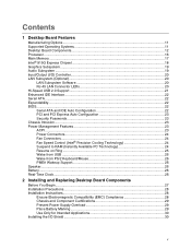
... 11 Desktop Board Components 12 Processor ...16 Main Memory ...17 Intel® 915G Express Chipset 18 Graphics Subsystem ...19 Audio Subsystem ...19 Input/Output (I/O) Controller 20 LAN Subsystem (Optional)...20 LAN Subsystem Software 20 RJ-45 LAN Connector LEDs 20 Hi-Speed USB 2.0 Support 21 Enhanced IDE Interface ...22 Serial ATA ...22 Expandability...22 BIOS...22 Serial ATA and IDE Auto Configuration 22 PCI and PCI Express Auto Configuration 23 Security Passwords...23 Chassis Intrusion...23 Power Management Features 23 ACPI...23 Power Connectors...24 Fan Connectors...24 Fan Speed...
... 11 Desktop Board Components 12 Processor ...16 Main Memory ...17 Intel® 915G Express Chipset 18 Graphics Subsystem ...19 Audio Subsystem ...19 Input/Output (I/O) Controller 20 LAN Subsystem (Optional)...20 LAN Subsystem Software 20 RJ-45 LAN Connector LEDs 20 Hi-Speed USB 2.0 Support 21 Enhanced IDE Interface ...22 Serial ATA ...22 Expandability...22 BIOS...22 Serial ATA and IDE Auto Configuration 22 PCI and PCI Express Auto Configuration 23 Security Passwords...23 Chassis Intrusion...23 Power Management Features 23 ACPI...23 Power Connectors...24 Fan Connectors...24 Fan Speed...
User Manual
Page 6
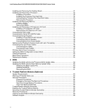
... (SATA) Cable 43 Connecting Internal Headers 44 Installing a Front Panel Audio Solution 45 Connecting USB 2.0 Headers 46 Connecting the Front Panel Header 46 Setting Up the Flexible 6-Channel Audio with Jack Re-tasking 47 Connecting Fan and Power Cables 48 Connecting Fan Cables 48 Connecting Power Cables 49 PCI Bus Add-In Card Connectors 51 Setting the BIOS Configuration Jumper Block 52 Clearing Passwords ...53 Back Panel Connectors...54 Replacing the Battery...55 3 BIOS Updating the BIOS with the Intel® Express BIOS Update Utility 59 Updating the BIOS with the Iflash Memory...
... (SATA) Cable 43 Connecting Internal Headers 44 Installing a Front Panel Audio Solution 45 Connecting USB 2.0 Headers 46 Connecting the Front Panel Header 46 Setting Up the Flexible 6-Channel Audio with Jack Re-tasking 47 Connecting Fan and Power Cables 48 Connecting Fan Cables 48 Connecting Power Cables 49 PCI Bus Add-In Card Connectors 51 Setting the BIOS Configuration Jumper Block 52 Clearing Passwords ...53 Back Panel Connectors...54 Replacing the Battery...55 3 BIOS Updating the BIOS with the Intel® Express BIOS Update Utility 59 Updating the BIOS with the Iflash Memory...
User Manual
Page 7
... PCI Express x16 Card and Covering the Back Panel VGA Port 41 20. Location of the PCI Bus and PCI Express Add-in Card, and Peripheral Interface Connectors for Flexible 6-Channel Audio System 47 24. Intel Desktop Boards D915GUX and D915GAG Components 14 3. Connecting the Processor Fan Heat Sink Cable to the Processor Fan Connector ........ 35 14. Connecting 2x10 Power Supply Cables 49 26. Install Processor ...34 12. Matching the Correct DIMM 38 18. Removing the Battery ...58 vii Connecting the Serial ATA Cable 43 22. Desktop Boards...
... PCI Express x16 Card and Covering the Back Panel VGA Port 41 20. Location of the PCI Bus and PCI Express Add-in Card, and Peripheral Interface Connectors for Flexible 6-Channel Audio System 47 24. Intel Desktop Boards D915GUX and D915GAG Components 14 3. Connecting the Processor Fan Heat Sink Cable to the Processor Fan Connector ........ 35 14. Connecting 2x10 Power Supply Cables 49 26. Install Processor ...34 12. Matching the Correct DIMM 38 18. Removing the Battery ...58 vii Connecting the Serial ATA Cable 43 22. Desktop Boards...
User Manual
Page 9
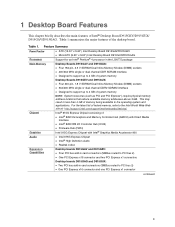
... as PCI and PCI Express*) require physical memory address locations that reduce available memory addresses above 3 GB. Feature Summary Form Factor Processor Main Memory Chipset Graphics Audio Expansion Capabilities • ATX (12.00" x 9.60") Intel Desktop Board D915GAV/D915GEV • MicroATX (9.60" x 9.60") Intel Desktop Board D915GUX/D915GAG Support for an Intel® Pentium® 4 processor in card connectors (SMBus routed to 4 GB of Intel® Desktop Board D915GEV/D915GUX/ D915GAV/D915GAG. For the latest list of tested memory...
... as PCI and PCI Express*) require physical memory address locations that reduce available memory addresses above 3 GB. Feature Summary Form Factor Processor Main Memory Chipset Graphics Audio Expansion Capabilities • ATX (12.00" x 9.60") Intel Desktop Board D915GAV/D915GEV • MicroATX (9.60" x 9.60") Intel Desktop Board D915GUX/D915GAG Support for an Intel® Pentium® 4 processor in card connectors (SMBus routed to 4 GB of Intel® Desktop Board D915GEV/D915GUX/ D915GAV/D915GAG. For the latest list of tested memory...
User Manual
Page 10
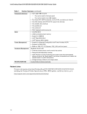
... devices) • One diskette drive interface • One parallel port • One serial port • PS/2* keyboard and mouse ports BIOS • Intel/AMI BIOS • 4 Mbit symmetrical flash memory • Support for SMBIOS • Intel® Rapid BIOS Boot • Intel® Express BIOS Update Power Management • Support for Advanced Configuration and Power Interface (ACPI) • Suspend to RAM (STR) • Wake on USB, PCI, PCI Express, PS/2, LAN, and front panel Hardware Management Hardware monitor with: • Three fan sensing inputs used to monitor fan...
... devices) • One diskette drive interface • One parallel port • One serial port • PS/2* keyboard and mouse ports BIOS • Intel/AMI BIOS • 4 Mbit symmetrical flash memory • Support for SMBIOS • Intel® Rapid BIOS Boot • Intel® Express BIOS Update Power Management • Support for Advanced Configuration and Power Interface (ACPI) • Suspend to RAM (STR) • Wake on USB, PCI, PCI Express, PS/2, LAN, and front panel Hardware Management Hardware monitor with: • Three fan sensing inputs used to monitor fan...
User Manual
Page 15
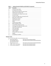
... voltage connector (2x2) Processor socket Processor fan header (4-pin, fan speed control) Main power connector (2x12) Diskette drive connector Primary IDE connector Battery Chassis intrusion header BIOS configuration jumper Trusted Platform Module (optional) Front chassis fan header (fan speed control) Serial ATA connectors (four) Power LED header Front panel header USB 2.0 headers PCI bus add-in card connectors Speaker PCI Express x1 connector Related Links: Go to the following links for more information about: • Intel Desktop Board D915GEV/D915GUX/ D915GAV/D915GAG • Supported...
... voltage connector (2x2) Processor socket Processor fan header (4-pin, fan speed control) Main power connector (2x12) Diskette drive connector Primary IDE connector Battery Chassis intrusion header BIOS configuration jumper Trusted Platform Module (optional) Front chassis fan header (fan speed control) Serial ATA connectors (four) Power LED header Front panel header USB 2.0 headers PCI bus add-in card connectors Speaker PCI Express x1 connector Related Links: Go to the following links for more information about: • Intel Desktop Board D915GEV/D915GUX/ D915GAV/D915GAG • Supported...
User Manual
Page 16
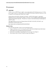
...information about: • Supported Intel processors for Desktop Board D915GEV/D915GUX/D915GAV/D915GAG http://support.intel.com/support/motherboards/desktop/ • Instructions on installing or upgrading the processor, page 32 in Chapter 2 • The location of the two power connectors, page 48 in damage to the desktop board and/or power supply. Intel Desktop Board D915GEV/D915GUX/D915GAV/D915GAG Product Guide Processor CAUTION Failure to use an ATX12V power supply, or not connecting the 12 V (2x2) processor core voltage power supply connector to Desktop Board D915GEV/D915GUX/D915GAV...
...information about: • Supported Intel processors for Desktop Board D915GEV/D915GUX/D915GAV/D915GAG http://support.intel.com/support/motherboards/desktop/ • Instructions on installing or upgrading the processor, page 32 in Chapter 2 • The location of the two power connectors, page 48 in damage to the desktop board and/or power supply. Intel Desktop Board D915GEV/D915GUX/D915GAV/D915GAG Product Guide Processor CAUTION Failure to use an ATX12V power supply, or not connecting the 12 V (2x2) processor core voltage power supply connector to Desktop Board D915GEV/D915GUX/D915GAV...
User Manual
Page 19
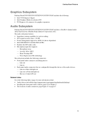
...: • Intel 915G Express Chipset • Intel Graphics Media Accelerator 900 • PCI Express x16 connector for graphics expansion Audio Subsystem Desktop Board D915GEV/D915GUX/D915GAV/D915GAG includes a flexible 6-channel audio subsystem based on a Realtek Semiconductor Corporation codec: The audio subsystem features: • Impedance sensing capability for jack re-tasking • S/N (signal-to-noise) ratio: > 90 dB • Power management support for ACPI 2.0 (driver dependent) • Intel 82801FB I/O Controller Hub (ICH6...
...: • Intel 915G Express Chipset • Intel Graphics Media Accelerator 900 • PCI Express x16 connector for graphics expansion Audio Subsystem Desktop Board D915GEV/D915GUX/D915GAV/D915GAG includes a flexible 6-channel audio subsystem based on a Realtek Semiconductor Corporation codec: The audio subsystem features: • Impedance sensing capability for jack re-tasking • S/N (signal-to-noise) ratio: > 90 dB • Power management support for ACPI 2.0 (driver dependent) • Intel 82801FB I/O Controller Hub (ICH6...
User Manual
Page 22
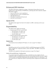
... The desktop boards support the following the instructions on page 59 in Chapter 3. You can be updated by specifying manual configuration in the BIOS automatically detects and configures the device for your computer, the autoconfiguration utility in the BIOS Setup program. 22 BIOS The BIOS provides the Power-On Self-Test (POST), the BIOS Setup program, the PCI/PCI Express and IDE auto-configuration utilities, and the video BIOS. Serial ATA and IDE Auto Configuration If you install a Serial ATA or IDE device (such as CD-ROM drives...
... The desktop boards support the following the instructions on page 59 in Chapter 3. You can be updated by specifying manual configuration in the BIOS automatically detects and configures the device for your computer, the autoconfiguration utility in the BIOS Setup program. 22 BIOS The BIOS provides the Power-On Self-Test (POST), the BIOS Setup program, the PCI/PCI Express and IDE auto-configuration utilities, and the video BIOS. Serial ATA and IDE Auto Configuration If you install a Serial ATA or IDE device (such as CD-ROM drives...

User Manual
Page 23
... feature uses a mechanical switch on the chassis that provides full ACPI support. 23 Chassis Intrusion The board supports a chassis security feature that add-in card. Desktop Board Features PCI and PCI Express Auto Configuration If you install a PCI/PCI Express add-in card in your computer, the PCI/PCI Express autoconfiguration utility in the BIOS automatically detects and configures the resources (IRQs, DMA channels, and I/O space) for that detects if the chassis cover has been removed. If only the supervisor password is booted...
... feature uses a mechanical switch on the chassis that provides full ACPI support. 23 Chassis Intrusion The board supports a chassis security feature that add-in card. Desktop Board Features PCI and PCI Express Auto Configuration If you install a PCI/PCI Express add-in card in your computer, the PCI/PCI Express autoconfiguration utility in the BIOS automatically detects and configures the resources (IRQs, DMA channels, and I/O space) for that detects if the chassis cover has been removed. If only the supervisor password is booted...
User Manual
Page 24
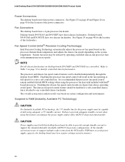
... support multiple wake events from the PCI and/or USB buses exceeds power supply capacity, the desktop board may be capable of delivering adequate +5 V standby current. It is recommended that processor fan speed control remain enabled (default BIOS setting) when using this desktop board must be reduced by operating controlled chassis and processor fans at the minimum necessary speeds. The chassis fan speed control feature should be disabled independently through the desktop board BIOS. Suspend to provide adequate standby current when using the processor fan...
... support multiple wake events from the PCI and/or USB buses exceeds power supply capacity, the desktop board may be capable of delivering adequate +5 V standby current. It is recommended that processor fan speed control remain enabled (default BIOS setting) when using this desktop board must be reduced by operating controlled chassis and processor fans at the minimum necessary speeds. The chassis fan speed control feature should be disabled independently through the desktop board BIOS. Suspend to provide adequate standby current when using the processor fan...
User Manual
Page 25
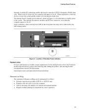
... interrupt be unmasked for the desktop board, refer to the Technical Product Specification by the LED turning amber. Figure 4. This includes the memory modules and PCI bus connectors, even when the computer appears to -RAM) sleep state. If the system has a dual-colored power LED on standby current requirements for correct operation 25 Desktop Board Features Instantly Available PC technology enables the board to enter the ACPI S3 (Suspend-to be...
... interrupt be unmasked for the desktop board, refer to the Technical Product Specification by the LED turning amber. Figure 4. This includes the memory modules and PCI bus connectors, even when the computer appears to -RAM) sleep state. If the system has a dual-colored power LED on standby current requirements for correct operation 25 Desktop Board Features Instantly Available PC technology enables the board to enter the ACPI S3 (Suspend-to be...
User Manual
Page 27
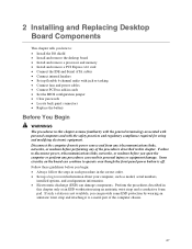
... : • Install the I/O shield • Install and remove the desktop board • Install and remove a processor and memory • Install and remove a PCI Express x16 card • Connect the IDE and Serial ATA cables • Connect internal headers • Set up a log to a metal part of the procedures described in this chapter only at an ESD workstation using and modifying electronic equipment. Disconnect the computer from its power source and from any telecommunications links, networks, or...
... : • Install the I/O shield • Install and remove the desktop board • Install and remove a processor and memory • Install and remove a PCI Express x16 card • Connect the IDE and Serial ATA cables • Connect internal headers • Set up a log to a metal part of the procedures described in this chapter only at an ESD workstation using and modifying electronic equipment. Disconnect the computer from its power source and from any telecommunications links, networks, or...
User Manual
Page 45
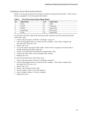
Remove the cover. 4. Locate the yellow front panel audio header. To restore back panel audio, follow these steps: 1. Turn off all peripheral devices connected to the front panel audio header, follow these steps: 1. Turn off the computer and disconnect the AC power cord. 3. Connect the audio cable to disable the back panel audio connectors. 5. Install a jumper on page 44 shows the location of the yellow front panel audio header. Install a correctly keyed and shielded front panel audio cable. 6. Replace the cover. 45 Table 9. Replace the cover...
Remove the cover. 4. Locate the yellow front panel audio header. To restore back panel audio, follow these steps: 1. Turn off all peripheral devices connected to the front panel audio header, follow these steps: 1. Turn off the computer and disconnect the AC power cord. 3. Connect the audio cable to disable the back panel audio connectors. 5. Install a jumper on page 44 shows the location of the yellow front panel audio header. Install a correctly keyed and shielded front panel audio cable. 6. Replace the cover. 45 Table 9. Replace the cover...

User Manual
Page 52
... the Power-On Self-Test (POST) runs, the BIOS displays the Maintenance Menu. Intel Desktop Board D915GEV/D915GUX/D915GAV/D915GAG Product Guide Setting the BIOS Configuration Jumper Block CAUTION Always turn off the power and unplug the power cord from a recovery diskette in unreliable computer operation. Figure 28 shows the location of the BIOS Configuration Jumper Block The three-pin BIOS jumper block enables all board configurations to clear passwords. Jumper Settings for the BIOS Setup Program Modes Jumper Setting 1 3 Mode Normal (default) (1-2) Description The BIOS uses the...
... the Power-On Self-Test (POST) runs, the BIOS displays the Maintenance Menu. Intel Desktop Board D915GEV/D915GUX/D915GAV/D915GAG Product Guide Setting the BIOS Configuration Jumper Block CAUTION Always turn off the power and unplug the power cord from a recovery diskette in unreliable computer operation. Figure 28 shows the location of the BIOS Configuration Jumper Block The three-pin BIOS jumper block enables all board configurations to clear passwords. Jumper Settings for the BIOS Setup Program Modes Jumper Setting 1 3 Mode Normal (default) (1-2) Description The BIOS uses the...

User Manual
Page 53
... the configuration jumper block is installed in the computer, and turn on the computer, and allow it to boot. 7. Installing and Replacing Desktop Board Components Clearing Passwords This procedure assumes that you confirm clearing the password. The computer starts the Setup program. Press and Setup displays a pop-up screen requesting that the board is set to the computer. Find the configuration jumper block (see Figure 28). 5. Setup displays the Maintenance menu. 8. Setup displays the maintenance menu again. 9. Remove the...
... the configuration jumper block is installed in the computer, and turn on the computer, and allow it to boot. 7. Installing and Replacing Desktop Board Components Clearing Passwords This procedure assumes that you confirm clearing the password. The computer starts the Setup program. Press and Setup displays a pop-up screen requesting that the board is set to the computer. Find the configuration jumper block (see Figure 28). 5. Setup displays the Maintenance menu. 8. Setup displays the maintenance menu again. 9. Remove the...

User Manual
Page 59
... use of Windows-based installation wizards. This runs the update program. 6. Navigate to the Intel World Wide Web site: http://support.intel.com/support/motherboards/desktop/ 2. Close all other applications. This chapter tells you can also save this file to update the BIOS by pressing the key after the Power-On Self-Test (POST) memory test begins and before the operating system boot begins. Updating the BIOS with the Intel Express BIOS Update utility: 1. The BIOS Setup...
... use of Windows-based installation wizards. This runs the update program. 6. Navigate to the Intel World Wide Web site: http://support.intel.com/support/motherboards/desktop/ 2. Close all other applications. This chapter tells you can also save this file to update the BIOS by pressing the key after the Power-On Self-Test (POST) memory test begins and before the operating system boot begins. Updating the BIOS with the Intel Express BIOS Update utility: 1. The BIOS Setup...

User Manual
Page 67
... new users. 13. Follow the instructions and create and document the locations for this Emergency Recovery Token file should be documented and stored in a secured location (vault, safe deposit box, offsite storage, etc.) in case they are needed in the task bar and automatically back up using the Key Transfer Manager when the removable media is the most frequently used to the new hard drive...
... new users. 13. Follow the instructions and create and document the locations for this Emergency Recovery Token file should be documented and stored in a secured location (vault, safe deposit box, offsite storage, etc.) in case they are needed in the task bar and automatically back up using the Key Transfer Manager when the removable media is the most frequently used to the new hard drive...
User Manual
Page 74
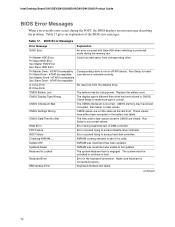
... Error Error during the POST, the BIOS displays an error message describing the problem. NVRAM is being checked to make sure device is correct. NVRAM was unable to make sure type is selected correctly. KB/Interface Error Keyboard interface test failed. ATAPI Incompatible Pri Slave Drive - Run Setup to set correct values. CMOS Settings Wrong CMOS values are invalid. Run Setup to reset values. HDC Failure Error occurred trying to access diskette drive controller...
... Error Error during the POST, the BIOS displays an error message describing the problem. NVRAM is being checked to make sure device is correct. NVRAM was unable to make sure type is selected correctly. KB/Interface Error Keyboard interface test failed. ATAPI Incompatible Pri Slave Drive - Run Setup to set correct values. CMOS Settings Wrong CMOS values are invalid. Run Setup to reset values. HDC Failure Error occurred trying to access diskette drive controller...


