User Manual
Page 6
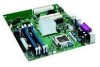
Intel Desktop Board D915GEV/D915GUX/D915GAV/D915GAG Product Guide Installing and Removing the Desktop Board 31 Installing and Removing a Processor 32 Installing a Processor 32 Installing the Processor Fan Heat Sink 34 Connecting the Processor Fan Heat Sink Cable 35 Removing the Processor 35 Installing ... Removing the PCI Express x16 Card 41 Connecting the IDE Cable...42 Connecting the Serial ATA (SATA) Cable 43 Connecting Internal Headers 44 Installing a Front Panel Audio Solution 45 Connecting USB 2.0 Headers 46 Connecting the Front Panel Header 46 Setting Up the Flexible 6-Channel...
Intel Desktop Board D915GEV/D915GUX/D915GAV/D915GAG Product Guide Installing and Removing the Desktop Board 31 Installing and Removing a Processor 32 Installing a Processor 32 Installing the Processor Fan Heat Sink 34 Connecting the Processor Fan Heat Sink Cable 35 Removing the Processor 35 Installing ... Removing the PCI Express x16 Card 41 Connecting the IDE Cable...42 Connecting the Serial ATA (SATA) Cable 43 Connecting Internal Headers 44 Installing a Front Panel Audio Solution 45 Connecting USB 2.0 Headers 46 Connecting the Front Panel Header 46 Setting Up the Flexible 6-Channel...
User Manual
Page 7
.... Back Panel LAN Connector LED Locations 20 4. Remove the Processor from the Protective Processor Cover/Do Not Touch 33 11. Matching the Correct DIMM 38 18. Intel Desktop Boards D915GUX and D915GAG Components 14 3. Installing the I/O Shield 30 6. Install Processor ...34 12. Connecting the IDE Cable 42 21. Location of Fan Headers 48 25. Desktop Boards D915GAV and...
.... Back Panel LAN Connector LED Locations 20 4. Remove the Processor from the Protective Processor Cover/Do Not Touch 33 11. Matching the Correct DIMM 38 18. Intel Desktop Boards D915GUX and D915GAG Components 14 3. Installing the I/O Shield 30 6. Install Processor ...34 12. Connecting the IDE Cable 42 21. Location of Fan Headers 48 25. Desktop Boards D915GAV and...
User Manual
Page 27
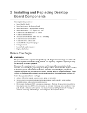
...panel power button is not available, you can damage components. 2 Installing and Replacing Desktop Board Components This chapter tells you how to: • Install the I/O shield • Install and remove the desktop board • Install and remove a processor and memory • Install and remove a PCI Express x16 card • Connect... the IDE and Serial ATA cables • Connect internal headers • Set up a log...
...panel power button is not available, you can damage components. 2 Installing and Replacing Desktop Board Components This chapter tells you how to: • Install the I/O shield • Install and remove the desktop board • Install and remove a processor and memory • Install and remove a PCI Express x16 card • Connect... the IDE and Serial ATA cables • Connect internal headers • Set up a log...
User Manual
Page 44
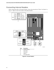
Figure 22 shows the location of the internal headers. Intel Desktop Board D915GEV/D915GUX/D915GAV/D915GAG Product Guide Connecting Internal Headers Before connecting cables to the internal headers, observe the precautions in "Before You Begin" on page 27. Port1L Port1R Port2R Sense_Send Port2L 12 34 56...10 GND Presence# Sense1_Ret Key (no pin) Sense2_Ret E USB A Power (+5V) DD+ Ground Key (no pin) USB B 1 2 Power (+5V) 3 4 D5 6 D+ 7 8 Ground 10 N/C D 9 No Connection On/Off 87 65 Reset Power LED 43 HD LED 3 21 1 C B Item A B C D E Description Chassis intrusion Power LED Front...
Figure 22 shows the location of the internal headers. Intel Desktop Board D915GEV/D915GUX/D915GAV/D915GAG Product Guide Connecting Internal Headers Before connecting cables to the internal headers, observe the precautions in "Before You Begin" on page 27. Port1L Port1R Port2R Sense_Send Port2L 12 34 56...10 GND Presence# Sense1_Ret Key (no pin) Sense2_Ret E USB A Power (+5V) DD+ Ground Key (no pin) USB B 1 2 Power (+5V) 3 4 D5 6 D+ 7 8 Ground 10 N/C D 9 No Connection On/Off 87 65 Reset Power LED 43 HD LED 3 21 1 C B Item A B C D E Description Chassis intrusion Power LED Front...
User Manual
Page 45
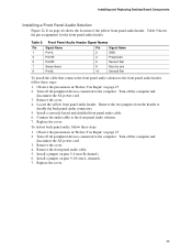
...Desktop Board Components Installing a Front Panel Audio Solution Figure 22, E on page 27. 2. Front Panel Audio Header Signal Names Pin Signal Name 1 Port1L 3 Port1R 5 Port2R 7 Sense Send 9 Port2L Pin Signal Name 2 GND 4 Presence# 6 Sense1 Ret 8 Key (no pin) 10 Sense2 Ret To install the cable that connects the front panel... audio solution to the front panel audio header, follow these steps: 1. Remove the cover. 4. Observe the precautions in "Before You ...
...Desktop Board Components Installing a Front Panel Audio Solution Figure 22, E on page 27. 2. Front Panel Audio Header Signal Names Pin Signal Name 1 Port1L 3 Port1R 5 Port2R 7 Sense Send 9 Port2L Pin Signal Name 2 GND 4 Presence# 6 Sense1 Ret 8 Key (no pin) 10 Sense2 Ret To install the cable that connects the front panel... audio solution to the front panel audio header, follow these steps: 1. Remove the cover. 4. Observe the precautions in "Before You ...
User Manual
Page 46
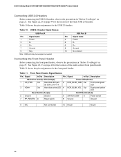
...panel green LED 4 HDR_BLNK_YEL Out Front panel yellow LED Reset Switch (Purple) On/Off Switch (Red) 5 Ground 7 FP_RESET# In Ground Reset switch 6 SWITCH_ON# In 8 Ground Power switch Ground 9 N/C Not connected 10 No pin No pin 46 Intel Desktop Board D915GEV/D915GUX/D915GAV/D915GAG Product Guide Connecting USB 2.0 Headers Before connecting...11. USB Port B Pin Signal name 2 Power 4 D- 6 D+ 8 Ground 10 No connect Connecting the Front Panel Header Before connecting the front panel header, observe the precautions in "Before You Begin" on page 27. Table 10 shows the ...
...panel green LED 4 HDR_BLNK_YEL Out Front panel yellow LED Reset Switch (Purple) On/Off Switch (Red) 5 Ground 7 FP_RESET# In Ground Reset switch 6 SWITCH_ON# In 8 Ground Power switch Ground 9 N/C Not connected 10 No pin No pin 46 Intel Desktop Board D915GEV/D915GUX/D915GAV/D915GAG Product Guide Connecting USB 2.0 Headers Before connecting...11. USB Port B Pin Signal name 2 Power 4 D- 6 D+ 8 Ground 10 No connect Connecting the Front Panel Header Before connecting the front panel header, observe the precautions in "Before You Begin" on page 27. Table 10 shows the ...
User Manual
Page 47
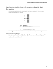
... 23. Installing and Replacing Desktop Board Components Setting Up the Flexible 6-Channel Audio with Jack Re-tasking After installing the Realtek audio driver from the Intel Express Installer CD-ROM, the multichannel audio feature can be enabled. Back Panel Audio Connectors for Flexible 6-Channel Audio System Multi-Channel Analog Audio Connect two speakers to the...
... 23. Installing and Replacing Desktop Board Components Setting Up the Flexible 6-Channel Audio with Jack Re-tasking After installing the Realtek audio driver from the Intel Express Installer CD-ROM, the multichannel audio feature can be enabled. Back Panel Audio Connectors for Flexible 6-Channel Audio System Multi-Channel Analog Audio Connect two speakers to the...
User Manual
Page 54
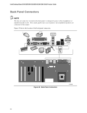
Back Panel Connectors OM16900 54 Intel Desktop Board D915GEV/D915GUX/D915GAV/D915GAG Product Guide Back Panel Connectors NOTE The line out connector, located on the back panel, is designed to this output. Poor audio quality may occur if passive (non-amplified) speakers are connected to power either headphones or amplified speakers only. Line In RJ45 Figure 29. Figure 29 shows the location of the back panel connectors.
Back Panel Connectors OM16900 54 Intel Desktop Board D915GEV/D915GUX/D915GAV/D915GAG Product Guide Back Panel Connectors NOTE The line out connector, located on the back panel, is designed to this output. Poor audio quality may occur if passive (non-amplified) speakers are connected to power either headphones or amplified speakers only. Line In RJ45 Figure 29. Figure 29 shows the location of the back panel connectors.
User Manual
Page 69
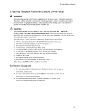
... do this can continue to operate even though the front panel power switch is disabled by default. The TPM may allow..., select Ok and press . 8. Power off . If you connect or disconnect cables, or install or remove any board components. Move the configuration jumper on the desktop board can result in the above . 10. Press the key to ... should automatically enter BIOS setup. 5. Trusted Platform Module Clearing Trusted Platform Module Ownership WARNING Disconnect the desktop board's power supply from its AC power source before you agree to the warning message select Ok and ...
... do this can continue to operate even though the front panel power switch is disabled by default. The TPM may allow..., select Ok and press . 8. Power off . If you connect or disconnect cables, or install or remove any board components. Move the configuration jumper on the desktop board can result in the above . 10. Press the key to ... should automatically enter BIOS setup. 5. Trusted Platform Module Clearing Trusted Platform Module Ownership WARNING Disconnect the desktop board's power supply from its AC power source before you agree to the warning message select Ok and ...


