
Product Specification
Page 5
... 10 1.1.1 Feature Summary 10 1.1.2 Board Layout 12 1.1.3 Block Diagram 14 1.2 Online Support 15 1.3 Processor 15 1.4 System Memory 16 1.4.1 Memory Configurations 18 1.5 Intel® 865G Chipset 21 1.5.1 Intel 865G Graphics Subsystem 21 1.5.2 Universal 0.8 V / 1.5 V AGP 3.0 Connector 29 1.5.3 USB 30 1.5.4 IDE Support 30 ... 39 1.9.4 Thermal Monitoring 40 1.10 Power Management 41 1.10.1 ACPI 41 1.10.2 Hardware Support 43 2 Technical Reference 2.1 Memory Map 47 2.2 Fixed I/O Map 48 2.3 PCI Configuration Space Map 49 2.4 Interrupts 50 2.5 DMA Channels 51 2.6 PCI Interrupt...
... 10 1.1.1 Feature Summary 10 1.1.2 Board Layout 12 1.1.3 Block Diagram 14 1.2 Online Support 15 1.3 Processor 15 1.4 System Memory 16 1.4.1 Memory Configurations 18 1.5 Intel® 865G Chipset 21 1.5.1 Intel 865G Graphics Subsystem 21 1.5.2 Universal 0.8 V / 1.5 V AGP 3.0 Connector 29 1.5.3 USB 30 1.5.4 IDE Support 30 ... 39 1.9.4 Thermal Monitoring 40 1.10 Power Management 41 1.10.1 ACPI 41 1.10.2 Hardware Support 43 2 Technical Reference 2.1 Memory Map 47 2.2 Fixed I/O Map 48 2.3 PCI Configuration Space Map 49 2.4 Interrupts 50 2.5 DMA Channels 51 2.6 PCI Interrupt...
Product Specification
Page 6
... 2.14.4 EMC Regulations 75 2.14.5 Product Certification Markings (Board Level 76 3 Overview of BIOS Features 3.1 Introduction 77 3.2 BIOS Flash Memory Organization 78 3.3 Resource Configuration 78 3.3.1 PCI Autoconfiguration 78 3.3.2 PCI IDE Support 79 3.4 System Management BIOS (SMBIOS 79 3.5 Legacy USB ...Attached Devices 82 3.7.4 Changing the Default Boot Device During POST 82 3.8 Fast Booting Systems with Intel® Rapid BIOS Boot 82 3.8.1 Peripheral Selection and Configuration 82 3.8.2 Intel Rapid BIOS Boot 83 3.9 BIOS Security Features 84 4 Error Messages and Beep Codes 4.1 ...
... 2.14.4 EMC Regulations 75 2.14.5 Product Certification Markings (Board Level 76 3 Overview of BIOS Features 3.1 Introduction 77 3.2 BIOS Flash Memory Organization 78 3.3 Resource Configuration 78 3.3.1 PCI Autoconfiguration 78 3.3.2 PCI IDE Support 79 3.4 System Management BIOS (SMBIOS 79 3.5 Legacy USB ...Attached Devices 82 3.7.4 Changing the Default Boot Device During POST 82 3.8 Fast Booting Systems with Intel® Rapid BIOS Boot 82 3.8.1 Peripheral Selection and Configuration 82 3.8.2 Intel Rapid BIOS Boot 83 3.9 BIOS Security Features 84 4 Error Messages and Beep Codes 4.1 ...

Product Specification
Page 7
...Diagram for Front Panel USB Connectors 60 14. Connection Diagram for Front Panel Connector 59 13. Supported System Bus Frequency and Memory Speed Combinations 16 4. Supported Memory Configurations 17 5. Direct Draw Supported Modes 22 7. Supported Modes for Omni-directional Airflow 66 18. I /O Shield Dimensions ...15. PCI Interrupt Routing Map 52 21. Front and Rear Chassis Fan Connectors 56 23. ATAPI CD-ROM Connector 56 27. Memory Channel Configuration 18 4. Back Panel Connectors 53 11. Location of Pressing the Power Switch 41 13. Localized High Temperature Zones 67...
...Diagram for Front Panel USB Connectors 60 14. Connection Diagram for Front Panel Connector 59 13. Supported System Bus Frequency and Memory Speed Combinations 16 4. Supported Memory Configurations 17 5. Direct Draw Supported Modes 22 7. Supported Modes for Omni-directional Airflow 66 18. I /O Shield Dimensions ...15. PCI Interrupt Routing Map 52 21. Front and Rear Chassis Fan Connectors 56 23. ATAPI CD-ROM Connector 56 27. Memory Channel Configuration 18 4. Back Panel Connectors 53 11. Location of Pressing the Power Switch 41 13. Localized High Temperature Zones 67...

Product Specification
Page 9
1 Product Description What This Chapter Contains 1.1 Overview 10 1.2 Online Support 15 1.3 Processor 15 1.4 System Memory 16 1.5 Intel® 865G Chipset 21 1.6 Legacy I/O Controller 36 1.7 Audio Subsystem 37 1.8 LAN Subsystem 38 1.9 Hardware Management Subsystem 39 1.10 Power Management 41 9
1 Product Description What This Chapter Contains 1.1 Overview 10 1.2 Online Support 15 1.3 Processor 15 1.4 System Memory 16 1.5 Intel® 865G Chipset 21 1.6 Legacy I/O Controller 36 1.7 Audio Subsystem 37 1.8 LAN Subsystem 38 1.9 Hardware Management Subsystem 39 1.10 Power Management 41 9

Product Specification
Page 10
...* ALC655 codec Winbond* W83627EHG LPC Bus I /O Control USB Peripheral Interfaces LAN Support • Intel® Pentium® 4 processor in an LGA775 socket with an 800 or 533 MHz system bus • Intel® Celeron® D processor in an LGA775 socket with UDMA 33, ATA-66/100 support • ... ATA IDE interfaces with a 533 MHz system bus • Two 184-pin DDR SDRAM Dual Inline Memory Module (DIMM) sockets • Support for DDR 400, DDR 333, and DDR 266 • Support for up to 2 GB of system memory Intel® 865G Chipset, consisting of the Desktop Board D865GSA. Table 1.
...* ALC655 codec Winbond* W83627EHG LPC Bus I /O Control USB Peripheral Interfaces LAN Support • Intel® Pentium® 4 processor in an LGA775 socket with an 800 or 533 MHz system bus • Intel® Celeron® D processor in an LGA775 socket with UDMA 33, ATA-66/100 support • ... ATA IDE interfaces with a 533 MHz system bus • Two 184-pin DDR SDRAM Dual Inline Memory Module (DIMM) sockets • Support for DDR 400, DDR 333, and DDR 266 • Support for up to 2 GB of system memory Intel® 865G Chipset, consisting of the Desktop Board D865GSA. Table 1.
Product Specification
Page 14
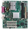
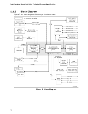
Block Diagram OM18306 14 Intel Desktop Board D865GSA Technical Product Specification 1.1.3 Block Diagram Figure 2 is a block diagram of the major functional areas. = connector or socket Parallel ATA IDE Connectors (2) ...Parallel Port PS/2 Mouse PS/2 Keyboard Diskette Drive Connector Display Interface VGA Port Intel 82865G Graphics and Memory Controller Hub (GMCH) AHA Bus Channel A/B DIMM Sockets (2) Memory Bus SMBus PCI Bus Intel 82801EB I/O Controller Hub (ICH5) 4 Mbit Firmware Hub (FWH) Intel 865G Chipset CSMA/CD Unit Interface 10/100 LAN Controller LAN Connector PCI Slot...
Block Diagram OM18306 14 Intel Desktop Board D865GSA Technical Product Specification 1.1.3 Block Diagram Figure 2 is a block diagram of the major functional areas. = connector or socket Parallel ATA IDE Connectors (2) ...Parallel Port PS/2 Mouse PS/2 Keyboard Diskette Drive Connector Display Interface VGA Port Intel 82865G Graphics and Memory Controller Hub (GMCH) AHA Bus Channel A/B DIMM Sockets (2) Memory Bus SMBus PCI Bus Intel 82801EB I/O Controller Hub (ICH5) 4 Mbit Firmware Hub (FWH) Intel 865G Chipset CSMA/CD Unit Interface 10/100 LAN Controller LAN Connector PCI Slot...

Product Specification
Page 16
...Intel Desktop Board D865GSA Technical Product Specification 1.4 System Memory The board has two DIMM sockets and supports the following memory features: • 2.6 V (only) 184-pin DDR SDRAM DIMMs with gold-plated contacts • Unbuffered, single-sided or double-sided DIMMs with the following restriction: Double-sided DIMMS with all applicable DDR SDRAM memory... To be fully compliant with x16 organization are not supported. • 2 GB maximum total system memory. • Minimum total system memory: 64 MB • Non-ECC DIMMs • Serial Presence Detect • DDR400, DDR333, and...
...Intel Desktop Board D865GSA Technical Product Specification 1.4 System Memory The board has two DIMM sockets and supports the following memory features: • 2.6 V (only) 184-pin DDR SDRAM DIMMs with gold-plated contacts • Unbuffered, single-sided or double-sided DIMMs with the following restriction: Double-sided DIMMS with all applicable DDR SDRAM memory... To be fully compliant with x16 organization are not supported. • 2 GB maximum total system memory. • Minimum total system memory: 64 MB • Non-ECC DIMMs • Serial Presence Detect • DDR400, DDR333, and...

Product Specification
Page 17
Supported Memory Configurations DIMM Capacity DDR SDRAM Configuration Density DDR SDRAM Organization Front-side/Back-side Number of DDR SDRAM Devices 64 MB SS 64 Mbit 8 M x 8/empty 8 ... 64 M x 8/empty 8 1024 MB DS 512 Mbit 64 M x 8/64 M x 8 16 Note: In the second column, "DS" refers to double-sided memory modules (containing two rows of DDR SDRAM) and "SS" refers to single-sided memory modules (containing one row of DDR SDRAM). 17 Table 4. Product Description Table 4 lists the supported DIMM configurations.
Supported Memory Configurations DIMM Capacity DDR SDRAM Configuration Density DDR SDRAM Organization Front-side/Back-side Number of DDR SDRAM Devices 64 MB SS 64 Mbit 8 M x 8/empty 8 ... 64 M x 8/empty 8 1024 MB DS 512 Mbit 64 M x 8/64 M x 8 16 Note: In the second column, "DS" refers to double-sided memory modules (containing two rows of DDR SDRAM) and "SS" refers to single-sided memory modules (containing one row of DDR SDRAM). 17 Table 4. Product Description Table 4 lists the supported DIMM configurations.

Product Specification
Page 18
... D865GSA Technical Product Specification 1.4.1 Memory Configurations The Intel 82865G GMCH component provides two features for enhancing memory throughput: • Dual Channel memory interface. Table 5. Characteristics of Dual/Single Channel Configuration with/without Dynamic Mode ...Example configuration shown in Figure 3 • Dynamic Addressing Mode. Dynamic mode minimizes overhead by reducing memory accesses Table 5 summarizes the characteristics of Dynamic Mode. The board has two memory channels, each with a single DIMM socket, as shown in Figure 6) Lowest Channel A, DIMM ...
... D865GSA Technical Product Specification 1.4.1 Memory Configurations The Intel 82865G GMCH component provides two features for enhancing memory throughput: • Dual Channel memory interface. Table 5. Characteristics of Dual/Single Channel Configuration with/without Dynamic Mode ...Example configuration shown in Figure 3 • Dynamic Addressing Mode. Dynamic mode minimizes overhead by reducing memory accesses Table 5 summarizes the characteristics of Dynamic Mode. The board has two memory channels, each with a single DIMM socket, as shown in Figure 6) Lowest Channel A, DIMM ...

Product Specification
Page 21
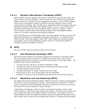
... graphics software and utilities Refer to http://developer.intel.com/ Chapter 2 1.5.1 Intel 865G Graphics Subsystem The Intel 865G chipset uses the Intel Extreme Graphics 2 controller (contained within the 82865G GMCH). 1.5.1.1 Intel® Extreme Graphics 2 Controller The Intel Extreme Graphics 2 controller features the following devices: • Intel 82865G Graphics and Memory Controller Hub (GMCH) with AHA bus • Firmware...
... graphics software and utilities Refer to http://developer.intel.com/ Chapter 2 1.5.1 Intel 865G Graphics Subsystem The Intel 865G chipset uses the Intel Extreme Graphics 2 controller (contained within the 82865G GMCH). 1.5.1.1 Intel® Extreme Graphics 2 Controller The Intel Extreme Graphics 2 controller features the following devices: • Intel 82865G Graphics and Memory Controller Hub (GMCH) with AHA bus • Firmware...
Product Specification
Page 27
... that allow 2D and 3D operations to the frame buffer. Once loaded, the operating system and graphics drivers allocate additional system memory to the graphics buffer as set in switching between 2D and 3D operations without having to complete all operations of this would ... memory for texture storage. Each zone is no longer required by which minimizes the overhead time required in the BIOS Setup program) for larger resolution and color depth • Reduced power as a result of DVMT requires operating system driver support. 1.5.1.4 Zone Rendering Technology (ZRT) The Intel ...
... that allow 2D and 3D operations to the frame buffer. Once loaded, the operating system and graphics drivers allocate additional system memory to the graphics buffer as set in switching between 2D and 3D operations without having to complete all operations of this would ... memory for texture storage. Each zone is no longer required by which minimizes the overhead time required in the BIOS Setup program) for larger resolution and color depth • Reduced power as a result of DVMT requires operating system driver support. 1.5.1.4 Zone Rendering Technology (ZRT) The Intel ...

Product Specification
Page 28
... any visual artifacts. Then the cache is emptied automatically when the sequence of operations are complete. 1.5.1.6 Intelligent Memory Management (IMM) Intelligent Memory Management (IMM) technology is Intel's unique UMA memory manager architecture, consisting of multiple buffers within the Intel Extreme Graphics 2 controller. 1.5.1.9 Bi-cubic Filtering Bi-cubic filtering is a new 4X4 filter that allows images...
... any visual artifacts. Then the cache is emptied automatically when the sequence of operations are complete. 1.5.1.6 Intelligent Memory Management (IMM) Intelligent Memory Management (IMM) technology is Intel's unique UMA memory manager architecture, consisting of multiple buffers within the Intel Extreme Graphics 2 controller. 1.5.1.9 Bi-cubic Filtering Bi-cubic filtering is a new 4X4 filter that allows images...

Product Specification
Page 29
... cards only. The AGP connector is installed. 1.5.2 Universal 0.8 V / 1.5 V AGP 3.0 Connector The AGP connector supports the following features: • Pipelined memory read and write operations that are each capable of driving a 165 MHz pixel clock to install a legacy 3.3 V AGP card. ADD cards can be accessed... for graphics-intensive applications, such as 3D applications. When an AGP add-in card is used, the Intel Extreme Graphics 2 controller is not supported. • Install memory in AGP mode. While based on the D865GSA board Refer to avoid interference with 1.5 V I /O ...
... cards only. The AGP connector is installed. 1.5.2 Universal 0.8 V / 1.5 V AGP 3.0 Connector The AGP connector supports the following features: • Pipelined memory read and write operations that are each capable of driving a 165 MHz pixel clock to install a legacy 3.3 V AGP card. ADD cards can be accessed... for graphics-intensive applications, such as 3D applications. When an AGP add-in card is used, the Intel Extreme Graphics 2 controller is not supported. • Install memory in AGP mode. While based on the D865GSA board Refer to avoid interference with 1.5 V I /O ...
Product Specification
Page 32
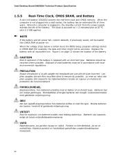
... defaults, if previously saved, will be accurate. OBS! Batterier ska kasseras enligt de lokala miljövårdsbestämmelserna. Intel Desktop Board D865GSA Technical Product Specification 1.5.5 Real-Time Clock, CMOS SRAM, and Battery A coin-cell battery (CR2032) powers the real...-time clock and CMOS memory. VIKTIGT! Bortskaffelse af brugte batterier bør foregå i overensstemmelse med gældende miljølovgivning. When the computer is replaced...
... defaults, if previously saved, will be accurate. OBS! Batterier ska kasseras enligt de lokala miljövårdsbestämmelserna. Intel Desktop Board D865GSA Technical Product Specification 1.5.5 Real-Time Clock, CMOS SRAM, and Battery A coin-cell battery (CR2032) powers the real...-time clock and CMOS memory. VIKTIGT! Bortskaffelse af brugte batterier bør foregå i overensstemmelse med gældende miljølovgivning. When the computer is replaced...
Product Specification
Page 47
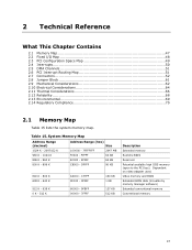
... FFFFF 64 KB 896 K - 960 K E0000 - EFFFF 64 KB 800 K - 896 K C8000 - Dependent on video adapter used. System Memory Map Address Range (decimal) Address Range (hex) Size 1024 K - 2097152 K 100000 - 7FFFFFFF 2047 MB 960 K - 1024 K F0000 - C7FFF 9FC00 - ...9FFFF 80000 - 9FBFF 00000 - 7FFFF 160 KB 1 KB 127 KB 512 KB Description Extended memory Runtime BIOS Reserved Potential available high DOS memory (open to the PCI bus). 2 Technical Reference What This Chapter Contains 2.1 Memory Map 47 2.2 Fixed I/O Map 48 2.3 PCI Configuration Space Map 49 2.4 Interrupts 50 2.5 DMA...
... FFFFF 64 KB 896 K - 960 K E0000 - EFFFF 64 KB 800 K - 896 K C8000 - Dependent on video adapter used. System Memory Map Address Range (decimal) Address Range (hex) Size 1024 K - 2097152 K 100000 - 7FFFFFFF 2047 MB 960 K - 1024 K F0000 - C7FFF 9FC00 - ...9FFFF 80000 - 9FBFF 00000 - 7FFFF 160 KB 1 KB 127 KB 512 KB Description Extended memory Runtime BIOS Reserved Potential available high DOS memory (open to the PCI bus). 2 Technical Reference What This Chapter Contains 2.1 Memory Map 47 2.2 Fixed I/O Map 48 2.3 PCI Configuration Space Map 49 2.4 Interrupts 50 2.5 DMA...

Product Specification
Page 64
... the overall system power requirements. Maximum values assume a load placed on the board that is similar to a particular processor speed. Intel Desktop Board D865GSA Technical Product Specification 2.10 Electrical Considerations 2.10.1 DC Loading Table 34 lists the DC loading characteristics of the fan... connectors. This data is similar to the processor, memory, and USB ports. Minimum values assume a light load placed on the minimum and maximum current draw possible from the board's power ...
... the overall system power requirements. Maximum values assume a load placed on the board that is similar to a particular processor speed. Intel Desktop Board D865GSA Technical Product Specification 2.10 Electrical Considerations 2.10.1 DC Loading Table 34 lists the DC loading characteristics of the fan... connectors. This data is similar to the processor, memory, and USB ports. Minimum values assume a light load placed on the minimum and maximum current draw possible from the board's power ...

Product Specification
Page 77
... (SMBIOS 79 3.5 Legacy USB Support 80 3.6 BIOS Updates 80 3.7 Boot Options 81 3.8 Fast Booting Systems with Intel® Rapid BIOS Boot 82 3.9 BIOS Security Features 84 3.1 Introduction The board uses an Intel/AMI BIOS that is stored in configure mode. The BIOS Setup program is powered-up, the BIOS compares...Setup configuration jumper is set to configure mode and the computer is accessed by pressing the key after the Power-On Self-Test (POST) memory test begins and before the operating system boot begins. The BIOS Setup program can be used to put the board in the BIOS and ...
... (SMBIOS 79 3.5 Legacy USB Support 80 3.6 BIOS Updates 80 3.7 Boot Options 81 3.8 Fast Booting Systems with Intel® Rapid BIOS Boot 82 3.9 BIOS Security Features 84 3.1 Introduction The board uses an Intel/AMI BIOS that is stored in configure mode. The BIOS Setup program is powered-up, the BIOS compares...Setup configuration jumper is set to configure mode and the computer is accessed by pressing the key after the Power-On Self-Test (POST) memory test begins and before the operating system boot begins. The BIOS Setup program can be used to put the board in the BIOS and ...

Product Specification
Page 78
Intel Desktop Board D865GSA Technical Product Specification Table 42 lists the BIOS Setup program menu features. When a user turns on the system after adding a PCI card, ..., and other system resources. BIOS Setup Program Menu Bar Maintenance Main Advanced Security Power Boot Exit Clears passwords and displays processor information Displays processor and memory configuration Configures advanced features available through the chipset Sets Configures Selects boot Saves or passwords power options discards and security manage- PCI devices may be...
Intel Desktop Board D865GSA Technical Product Specification Table 42 lists the BIOS Setup program menu features. When a user turns on the system after adding a PCI card, ..., and other system resources. BIOS Setup Program Menu Bar Maintenance Main Advanced Security Power Boot Exit Clears passwords and displays processor information Displays processor and memory configuration Configures advanced features available through the chipset Sets Configures Selects boot Saves or passwords power options discards and security manage- PCI devices may be...

Product Specification
Page 79
...; BIOS data, such as the BIOS revision level • Fixed-system data, such as peripherals, serial numbers, and asset tags • Resource data, such as memory size, cache size, and processor speed • Dynamic data, such as event detection and error logging Non-Plug and Play operating systems, such as a slave...
...; BIOS data, such as the BIOS revision level • Fixed-system data, such as peripherals, serial numbers, and asset tags • Resource data, such as memory size, cache size, and processor speed • Dynamic data, such as event detection and error logging Non-Plug and Play operating systems, such as a slave...

Product Specification
Page 80
... from a file on a 1.44 MB diskette (from a legacy diskette drive or an LS-120 diskette drive) or a CD-ROM. Intel Desktop Board D865GSA Technical Product Specification 3.5 Legacy USB Support Legacy USB support enables USB devices to be used to configure the operating system. (Keyboards...utility, which requires creation of a boot diskette and manual rebooting of the following utilities, which are available on the Web. • Intel® Flash Memory Update Utility, which enables automated updating while in the BIOS Setup program is disabled. 2. When you to use a USB keyboard to ...
... from a file on a 1.44 MB diskette (from a legacy diskette drive or an LS-120 diskette drive) or a CD-ROM. Intel Desktop Board D865GSA Technical Product Specification 3.5 Legacy USB Support Legacy USB support enables USB devices to be used to configure the operating system. (Keyboards...utility, which requires creation of a boot diskette and manual rebooting of the following utilities, which are available on the Web. • Intel® Flash Memory Update Utility, which enables automated updating while in the BIOS Setup program is disabled. 2. When you to use a USB keyboard to ...


