Manual
Page 4
... Processor System Memory Memory Configurations Intel 865G Chipset Intel 865G Graphics Subsystem USB Support IDE Support Real-Time Clock, CMOS SRAM and Battery I/O Controller Audio Subsystem Audio Connectors LAN Subsystem Hardware Management Subsystem Power Management ACPI Hardware Support Chapter 2 System Board Options Overview of Jumper Settings System Board Jumper Settings Motherboard Connectors Front Panel Connectors Upgrading the CPU Installing...
... Processor System Memory Memory Configurations Intel 865G Chipset Intel 865G Graphics Subsystem USB Support IDE Support Real-Time Clock, CMOS SRAM and Battery I/O Controller Audio Subsystem Audio Connectors LAN Subsystem Hardware Management Subsystem Power Management ACPI Hardware Support Chapter 2 System Board Options Overview of Jumper Settings System Board Jumper Settings Motherboard Connectors Front Panel Connectors Upgrading the CPU Installing...
Manual
Page 7
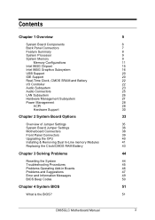
... connector P Diskette drive connector Q Parallel ATA IDE connectors R Front chassis fan connector S Chassis intrusion connector T 4 Mbit Firmware Hub (FWH) U Speaker V BIOS Setup configuration jumper block W Aux front panel power LED connector X Front panel connector Y Serial ATA connectors Z Front panel USB connectors AA Intel 82801EB I/O Controller Hub (ICH5) BB Front Panel USB connector CC Battery DD PCI bus add-in card connectors EE Aux line-in connector D865GLC Motherboard Manual...
... connector P Diskette drive connector Q Parallel ATA IDE connectors R Front chassis fan connector S Chassis intrusion connector T 4 Mbit Firmware Hub (FWH) U Speaker V BIOS Setup configuration jumper block W Aux front panel power LED connector X Front panel connector Y Serial ATA connectors Z Front panel USB connectors AA Intel 82801EB I/O Controller Hub (ICH5) BB Front Panel USB connector CC Battery DD PCI bus add-in card connectors EE Aux line-in connector D865GLC Motherboard Manual...
Manual
Page 8
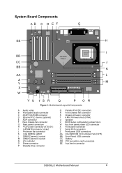
... I /O shield to match the motherboard. Back Panel Connectors The motherboard external IO connectors are attached to the computer should be easily upgraded in the future without having to resort to PS/2 keyboard and mouse connectors as well as one serial port, one parallel port, two USB ports, one LAN Port and the audio connectors. D865GLC Motherboard Manual 7 Simply change...
... I /O shield to match the motherboard. Back Panel Connectors The motherboard external IO connectors are attached to the computer should be easily upgraded in the future without having to resort to PS/2 keyboard and mouse connectors as well as one serial port, one parallel port, two USB ports, one LAN Port and the audio connectors. D865GLC Motherboard Manual 7 Simply change...
Manual
Page 9
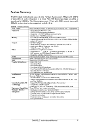
... Controller USB Peripheral Interfaces LAN Support BIOS Instantly Available PC Technology Expansion Capabilities Hardware Monitor Subsystem - Intel/AMI BIOS (resident in card connectors - Voltage sense to detect out of range thermal values - Table 1: Feature Summary Form Factor ...panel, PS/2 devices and USB ports Three PCI bus add-in the 4 Mbit FWH) - Three fan connectors - Fan speed control D865GLC Motherboard Manual 8 Support for Advanced Configuration and Power Interface (ACPI), Plug and Play SMBIOS - Eight USB Ports - Feature Summary The D865GLC motherboard supports Intel...
... Controller USB Peripheral Interfaces LAN Support BIOS Instantly Available PC Technology Expansion Capabilities Hardware Monitor Subsystem - Intel/AMI BIOS (resident in card connectors - Voltage sense to detect out of range thermal values - Table 1: Feature Summary Form Factor ...panel, PS/2 devices and USB ports Three PCI bus add-in the 4 Mbit FWH) - Three fan connectors - Fan speed control D865GLC Motherboard Manual 8 Support for Advanced Configuration and Power Interface (ACPI), Plug and Play SMBIOS - Eight USB Ports - Feature Summary The D865GLC motherboard supports Intel...
Manual
Page 21
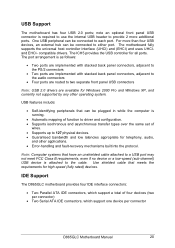
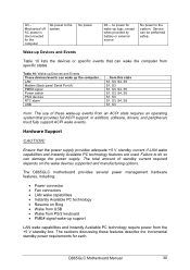
... isochronous and asynchronous transfer types over the same set of four devices (two per connector) • Two Serial ATA IDE connectors, which support one device per connector D865GLC Motherboard Manual 20 One USB peripheral can be plugged in while the computer is attached to... The motherboard has four USB 2.0 ports; note an optional front panel USB connector is as follows: • Two ports are implemented with stacked back panel connectors, adjacent to the PS/2 connectors • Two ports are implemented with stacked back panel connectors, adjacent to the audio connectors •...
... isochronous and asynchronous transfer types over the same set of four devices (two per connector) • Two Serial ATA IDE connectors, which support one device per connector D865GLC Motherboard Manual 20 One USB peripheral can be plugged in while the computer is attached to... The motherboard has four USB 2.0 ports; note an optional front panel USB connector is as follows: • Two ports are implemented with stacked back panel connectors, adjacent to the PS/2 connectors • Two ports are implemented with stacked back panel connectors, adjacent to the audio connectors •...
Manual
Page 23
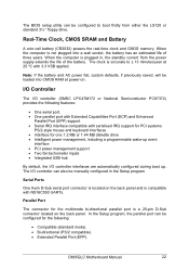
...) powers the real-time clock and CMOS memory. The BIOS setup utility can be configured to ± 13 minutes/year at power-on the back panel. Note: If the battery and AC power fail, custom defaults, if previously saved, will be loaded into a wall socket, the battery has an estimated... 3½ " floppy drive. When the computer is accurate to boot firstly from the power supply extends the life of three years. Parallel Port The connector for one 1.2 MB or 1.44 MB diskette drive • Intelligent power management, including a programmable wake-up . D865GLC Motherboard Manual 22
...) powers the real-time clock and CMOS memory. The BIOS setup utility can be configured to ± 13 minutes/year at power-on the back panel. Note: If the battery and AC power fail, custom defaults, if previously saved, will be loaded into a wall socket, the battery has an estimated... 3½ " floppy drive. When the computer is accurate to boot firstly from the power supply extends the life of three years. Parallel Port The connector for one 1.2 MB or 1.44 MB diskette drive • Intelligent power management, including a programmable wake-up . D865GLC Motherboard Manual 22

Manual
Page 24
...; Enhanced Capabilities Port (ECP). Audio Subsystem The D865GLC motherboard provides a Flex 6 audio subsystem based on /reset. The +5 V lines to these connectors are located on /reset password can be specified in Setup. A power on the back panel. The keyboard controller contains the AMI Megakey keyboard ...by jumping to the beginning of device has been connected. • Split digital/analog architecture for the following features: • Intel 82801EB I /O controller is removed. The keyboard controller also supports the hot-key sequence for power on the Analog Devices AD1985 ...
...; Enhanced Capabilities Port (ECP). Audio Subsystem The D865GLC motherboard provides a Flex 6 audio subsystem based on /reset. The +5 V lines to these connectors are located on /reset password can be specified in Setup. A power on the back panel. The keyboard controller contains the AMI Megakey keyboard ...by jumping to the beginning of device has been connected. • Split digital/analog architecture for the following features: • Intel 82801EB I /O controller is removed. The keyboard controller also supports the hot-key sequence for power on the Analog Devices AD1985 ...

Manual
Page 25
The subsystem has the following connectors: • ATAPI-style CDROM connector • Front panel audio connector, including pins for S/PDIF Back Panel Connector D865GLC Motherboard Manual 24 The available configurations are configurable through the audio devices derivers. Figure 10: Adapter for : o Line In o Mic in • Back panel audio connectors that are shown below: Figure 9: Back Panel Audio Connector Options Note: To access the S/PDIF signal with the 5.1 Digital Shared Jack option, connect a 1/8-inch stereo phone plug to RCA jack adapter/splitter as shown in Figure 10.
The subsystem has the following connectors: • ATAPI-style CDROM connector • Front panel audio connector, including pins for S/PDIF Back Panel Connector D865GLC Motherboard Manual 24 The available configurations are configurable through the audio devices derivers. Figure 10: Adapter for : o Line In o Mic in • Back panel audio connectors that are shown below: Figure 9: Back Panel Audio Connector Options Note: To access the S/PDIF signal with the 5.1 Digital Shared Jack option, connect a 1/8-inch stereo phone plug to RCA jack adapter/splitter as shown in Figure 10.

Manual
Page 26
Audio Connectors Front Panel Audio connector A 2 x 5-pin connector provides mic in and line out signals for front panel audio connectors. D865GLC Motherboard Manual 25 ATAPI CDROM Audio Connector A 1 x 4-pin ATAPI-style connector connects an internal ATAPI CD-ROM drive to the audio subsystem. Auxiliary Line In Connector A 1 x 4-pin ATAPI-style connector connects the left and right channel signals of an internal audio device to the audio mixer.
Audio Connectors Front Panel Audio connector A 2 x 5-pin connector provides mic in and line out signals for front panel audio connectors. D865GLC Motherboard Manual 25 ATAPI CDROM Audio Connector A 1 x 4-pin ATAPI-style connector connects an internal ATAPI CD-ROM drive to the audio subsystem. Auxiliary Line In Connector A 1 x 4-pin ATAPI-style connector connects the left and right channel signals of an internal audio device to the audio mixer.
Manual
Page 27
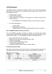
...8226; Configuration EEPROM that supports the following table describes the LED states when the board is not established. LAN link is selected. The computer is operating. Table 7: LAN Connector LEDs LED Colour LED State Green Off Green On Yellow Off Yellow On (steady...powered up from suspend state (Wake-On-LAN † technology) Intel ® 82562EZ Platform LAN Connect Device The Intel 82562EZ component provides an interface to the back panel RJ-45 connector with integrated LEDs. D865GLC Motherboard Manual 26 Feature of the ICH5 (with another computer on the ...
...8226; Configuration EEPROM that supports the following table describes the LED states when the board is not established. LAN link is selected. The computer is operating. Table 7: LAN Connector LEDs LED Colour LED State Green Off Green On Yellow Off Yellow On (steady...powered up from suspend state (Wake-On-LAN † technology) Intel ® 82562EZ Platform LAN Connect Device The Intel 82562EZ component provides an interface to the back panel RJ-45 connector with integrated LEDs. D865GLC Motherboard Manual 26 Feature of the ICH5 (with another computer on the ...
Manual
Page 31
... requirements for the computer No power to do so can wake the computer from the +5 V standby line. D865GLC Motherboard Manual 30 LAN Modem (Back panel Serial Port A) PME# signal Power switch PS/2 devices RTC alarm USB ...from this state S1, S3, S4...support LAN wake capabilities and Instantly Available PC technology require power from specific states. The D865GLC motherboard provides several power management hardware features, including: • Power connector • Fan connectors • LAN wake capabilities • Instantly Available PC technology • Resume on the...
... requirements for the computer No power to do so can wake the computer from the +5 V standby line. D865GLC Motherboard Manual 30 LAN Modem (Back panel Serial Port A) PME# signal Power switch PS/2 devices RTC alarm USB ...from this state S1, S3, S4...support LAN wake capabilities and Instantly Available PC technology require power from specific states. The D865GLC motherboard provides several power management hardware features, including: • Power connector • Fan connectors • LAN wake capabilities • Instantly Available PC technology • Resume on the...

Manual
Page 38
... mode. Note: There is in signals are routed back to the line connector. D865GLC Motherboard Manual 37 Table 12: Front Panel Audio Jumper Settings Function Jumper Configuration J9A2 Normal 5 - 6 The audio line signals are available for front panel audio connectors on . Table 12a: Front panel Audio Connector Pin Signal name Pin 1 MIC_IN 2 3 MIC_BIAS 4 5 RIGHT_OUT 6 7 Ground 8 9 LEFT_OUT 10 Signal...
... mode. Note: There is in signals are routed back to the line connector. D865GLC Motherboard Manual 37 Table 12: Front Panel Audio Jumper Settings Function Jumper Configuration J9A2 Normal 5 - 6 The audio line signals are available for front panel audio connectors on . Table 12a: Front panel Audio Connector Pin Signal name Pin 1 MIC_IN 2 3 MIC_BIAS 4 5 RIGHT_OUT 6 7 Ground 8 9 LEFT_OUT 10 Signal...
Manual
Page 39
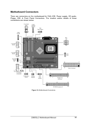
... 7 10 1 2 Front USB Header 7 10 Serial ATA Header 0& 1 1 2 Intel 865G Chipset ` 8 9 Front Panel Connectors 1 Configuration Jumper 1 Chassis Intrusion 1 FAN Front Chassis PSU ATX 12V PGA 478 Socket 1 CPU FAN 20 11 10 Power Connector 1 2 31 15 Floppy Drive 33 Connector 2 20 40 1 PCI IDE Connector x2 39 bb Figure 13: Motherboard Connectors D865GLC Motherboard Manual 38 Motherboard Connectors There are shown below.
... 7 10 1 2 Front USB Header 7 10 Serial ATA Header 0& 1 1 2 Intel 865G Chipset ` 8 9 Front Panel Connectors 1 Configuration Jumper 1 Chassis Intrusion 1 FAN Front Chassis PSU ATX 12V PGA 478 Socket 1 CPU FAN 20 11 10 Power Connector 1 2 31 15 Floppy Drive 33 Connector 2 20 40 1 PCI IDE Connector x2 39 bb Figure 13: Motherboard Connectors D865GLC Motherboard Manual 38 Motherboard Connectors There are shown below.

Manual
Page 40
Connector This goes to display if the computer is in use. Power L.E.D. This attaches to the power L.E.D on the front panel, to the Hard Disk L.E.D. D865GLC Motherboard Manual 39 on the front panel, which lights up when the IDE Hard Disk is active or not. C - Power On/Off... When these pins are often connected to perform a cold reboot. B - They are shorted, it turns the computer on and off. Figure 14: Front panel connectors A- Reset switch connector...
Connector This goes to display if the computer is in use. Power L.E.D. This attaches to the power L.E.D on the front panel, to the Hard Disk L.E.D. D865GLC Motherboard Manual 39 on the front panel, which lights up when the IDE Hard Disk is active or not. C - Power On/Off... When these pins are often connected to perform a cold reboot. B - They are shorted, it turns the computer on and off. Figure 14: Front panel connectors A- Reset switch connector...
Manual
Page 49
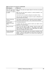
... Setup. Make sure the front panel connector is set to allow entry into Setup (Chapter 2). Power-on light does not go on If the system is operating normally, check the connector between the system board and the front panel. Setup, can 't enter Setup to your dealer service department / Technical Support. D865GLC Motherboard Manual 48 Provide this information...
... Setup. Make sure the front panel connector is set to allow entry into Setup (Chapter 2). Power-on light does not go on If the system is operating normally, check the connector between the system board and the front panel. Setup, can 't enter Setup to your dealer service department / Technical Support. D865GLC Motherboard Manual 48 Provide this information...
Manual
Page 56
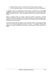
• Suspend/resume switch connected to the front panel sleep connector. • From the operating system, such as the Suspend menu item in standby mode, the system retains the ability to respond to external interrupts and ... power consumption by default, but the operating system must support an APM driver for the power-management features to the monitor. D865GLC Motherboard Manual 55 Any keyboard or mouse activity brings the system out of standby mode and immediately restores power to work. Power-management mode can be ...
• Suspend/resume switch connected to the front panel sleep connector. • From the operating system, such as the Suspend menu item in standby mode, the system retains the ability to respond to external interrupts and ... power consumption by default, but the operating system must support an APM driver for the power-management features to the monitor. D865GLC Motherboard Manual 55 Any keyboard or mouse activity brings the system out of standby mode and immediately restores power to work. Power-management mode can be ...

Manual
Page 99
... Ground 18 -5 V 19 +5 V 20 +5 V Table 60: Front Panel I/O Connectors Connector Pin Signal Name Sleep/Power 2 +5 V LED Green Sleep/Power 4 0v LED Yellow Power Switch 6 SWITCH ON Power Switch 8 Ground No connection 10 None Connector HDD LED HDD LED RESET RESET No connection Pin Signal Name 1 +5V HDD 3 OV HDD 5 RESET 7 Ground 9 +5V D865GLC Motherboard Manual 98
... Ground 18 -5 V 19 +5 V 20 +5 V Table 60: Front Panel I/O Connectors Connector Pin Signal Name Sleep/Power 2 +5 V LED Green Sleep/Power 4 0v LED Yellow Power Switch 6 SWITCH ON Power Switch 8 Ground No connection 10 None Connector HDD LED HDD LED RESET RESET No connection Pin Signal Name 1 +5V HDD 3 OV HDD 5 RESET 7 Ground 9 +5V D865GLC Motherboard Manual 98


