Manual
Page 4
... System Processor System Memory Memory Configurations Intel 865G Chipset Intel 865G Graphics Subsystem USB Support IDE Support Real-Time Clock, CMOS SRAM and Battery I/O Controller Audio Subsystem Audio Connectors LAN Subsystem Hardware Management Subsystem Power Management ACPI Hardware Support Chapter 2 System Board Options Overview of Jumper Settings System Board Jumper Settings Motherboard Connectors Front Panel Connectors Upgrading...
... System Processor System Memory Memory Configurations Intel 865G Chipset Intel 865G Graphics Subsystem USB Support IDE Support Real-Time Clock, CMOS SRAM and Battery I/O Controller Audio Subsystem Audio Connectors LAN Subsystem Hardware Management Subsystem Power Management ACPI Hardware Support Chapter 2 System Board Options Overview of Jumper Settings System Board Jumper Settings Motherboard Connectors Front Panel Connectors Upgrading...
Manual
Page 7
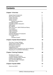
...Board Components AB C D E F G EE H DD CC BB AA Z Y X W PGA 478 I Socket Intel 865G Chipset ` J K L M VU TS R Q P ON Figure 1: Motherboard Layout & Components A Audio codec B Front panel audio connector C ATAPI CD-ROM connector D Ethernet PLC device (optional) E AGP connector F Rear chassis fan connector G Back panel connectors H +12V power connector (ATX12V) I mPGA478 processor socket J Processor fan connector K Intel... connector Y Serial ATA connectors Z Front panel USB connectors AA Intel 82801EB I/O Controller Hub (ICH5) BB Front Panel USB connector CC Battery DD PCI ...
...Board Components AB C D E F G EE H DD CC BB AA Z Y X W PGA 478 I Socket Intel 865G Chipset ` J K L M VU TS R Q P ON Figure 1: Motherboard Layout & Components A Audio codec B Front panel audio connector C ATAPI CD-ROM connector D Ethernet PLC device (optional) E AGP connector F Rear chassis fan connector G Back panel connectors H +12V power connector (ATX12V) I mPGA478 processor socket J Processor fan connector K Intel... connector Y Serial ATA connectors Z Front panel USB connectors AA Intel 82801EB I/O Controller Hub (ICH5) BB Front Panel USB connector CC Battery DD PCI ...
Manual
Page 8
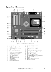
D865GLC Motherboard Manual 7 Simply change the I /O shield provides external access to PS/2 keyboard and mouse connectors as well as one serial port, one parallel port, two USB ports, one LAN Port and the audio connectors. This shield serves several purposes: • It protects the sensitive motherboard from any external EMC interference. • It stops the...
D865GLC Motherboard Manual 7 Simply change the I /O shield provides external access to PS/2 keyboard and mouse connectors as well as one serial port, one parallel port, two USB ports, one LAN Port and the audio connectors. This shield serves several purposes: • It protects the sensitive motherboard from any external EMC interference. • It stops the...
Manual
Page 9
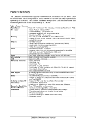
...sense inputs used to 4GB of DDR266, DDR333 or DDR400 SRAM DIMMs using 2.5V memory Intel 865G Chipset - Integrated retention mechanism Flex 6 audio subsystem using the Intel 82562EZ Platform LAN Connect (PLC) device - Three fan connectors - The Celeron processor 478... Advanced Configuration and Power Interface (ACPI), Plug and Play SMBIOS - Intel® 82801EB I/O Controller Hub (ICH5) - 4 Mbit Firmware Hub (FWH) Intel Extreme Graphics 2 controller - Feature Summary The D865GLC motherboard supports Intel Pentium 4 processors 478 pin with 512KB of second-level cache integrated ...
...sense inputs used to 4GB of DDR266, DDR333 or DDR400 SRAM DIMMs using 2.5V memory Intel 865G Chipset - Integrated retention mechanism Flex 6 audio subsystem using the Intel 82562EZ Platform LAN Connect (PLC) device - Three fan connectors - The Celeron processor 478... Advanced Configuration and Power Interface (ACPI), Plug and Play SMBIOS - Intel® 82801EB I/O Controller Hub (ICH5) - 4 Mbit Firmware Hub (FWH) Intel Extreme Graphics 2 controller - Feature Summary The D865GLC motherboard supports Intel Pentium 4 processors 478 pin with 512KB of second-level cache integrated ...
Manual
Page 21
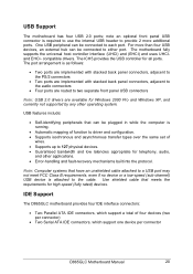
... built into the protocol. USB features include: • Self-identifying peripherals that meets the requirements for telephony, audio, and other operating system. IDE Support The D865GLC motherboard provides four IDE interface connectors: • Two Parallel ATA IDE connectors, which support a total of wires. ...set of four devices (two per connector) • Two Serial ATA IDE connectors, which support one device per connector D865GLC Motherboard Manual 20 compatible drivers. Use shielded cable that can be plugged in while the computer is required to use the internal...
... built into the protocol. USB features include: • Self-identifying peripherals that meets the requirements for telephony, audio, and other operating system. IDE Support The D865GLC motherboard provides four IDE interface connectors: • Two Parallel ATA IDE connectors, which support a total of wires. ...set of four devices (two per connector) • Two Serial ATA IDE connectors, which support one device per connector D865GLC Motherboard Manual 20 compatible drivers. Use shielded cable that can be plugged in while the computer is required to use the internal...

Manual
Page 24
...been connected. • Split digital/analog architecture for power on the Analog Devices AD1985 codec. Audio Subsystem The D865GLC motherboard provides a Flex 6 audio subsystem based on /reset. • Enhanced Capabilities Port (ECP). The keyboard controller contains the...that supports a single dynamic, condenser, or electrets microphone D865GLC Motherboard Manual 23 The audio subsystem supports the following features: • Intel 82801EB I /O controller is software compatible with Auto Topology Switching that enables the audio codec to recognise what device is removed. The +5 ...
...been connected. • Split digital/analog architecture for power on the Analog Devices AD1985 codec. Audio Subsystem The D865GLC motherboard provides a Flex 6 audio subsystem based on /reset. • Enhanced Capabilities Port (ECP). The keyboard controller contains the...that supports a single dynamic, condenser, or electrets microphone D865GLC Motherboard Manual 23 The audio subsystem supports the following features: • Intel 82801EB I /O controller is software compatible with Auto Topology Switching that enables the audio codec to recognise what device is removed. The +5 ...

Manual
Page 25
Figure 10: Adapter for : o Line In o Mic in • Back panel audio connectors that are shown below: Figure 9: Back Panel Audio Connector Options Note: To access the S/PDIF signal with the 5.1 Digital Shared Jack option, connect a 1/8-inch stereo phone plug to RCA jack adapter/splitter as shown in Figure 10. The subsystem has the following connectors: • ATAPI-style CDROM connector • Front panel audio connector, including pins for S/PDIF Back Panel Connector D865GLC Motherboard Manual 24 The available configurations are configurable through the audio devices derivers.
Figure 10: Adapter for : o Line In o Mic in • Back panel audio connectors that are shown below: Figure 9: Back Panel Audio Connector Options Note: To access the S/PDIF signal with the 5.1 Digital Shared Jack option, connect a 1/8-inch stereo phone plug to RCA jack adapter/splitter as shown in Figure 10. The subsystem has the following connectors: • ATAPI-style CDROM connector • Front panel audio connector, including pins for S/PDIF Back Panel Connector D865GLC Motherboard Manual 24 The available configurations are configurable through the audio devices derivers.

Manual
Page 26
ATAPI CDROM Audio Connector A 1 x 4-pin ATAPI-style connector connects an internal ATAPI CD-ROM drive to the audio subsystem. D865GLC Motherboard Manual 25 Audio Connectors Front Panel Audio connector A 2 x 5-pin connector provides mic in and line out signals for front panel audio connectors. Auxiliary Line In Connector A 1 x 4-pin ATAPI-style connector connects the left and right channel signals of an internal audio device to the audio mixer.
ATAPI CDROM Audio Connector A 1 x 4-pin ATAPI-style connector connects an internal ATAPI CD-ROM drive to the audio subsystem. D865GLC Motherboard Manual 25 Audio Connectors Front Panel Audio connector A 2 x 5-pin connector provides mic in and line out signals for front panel audio connectors. Auxiliary Line In Connector A 1 x 4-pin ATAPI-style connector connects the left and right channel signals of an internal audio device to the audio mixer.
Manual
Page 37
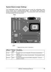
... Intel 865G Chipset ` PGA 478 Socket J9J4 Figure 12: Single-Jumper Configurations Table 11: Configuration Jumper Settings Function Jumper Configuration J9J4 Normal 1-2 The BIOS uses current configuration information and passwords for booting. The following figure shows the location of front panel audio. A recovery diskette is displayed. The maintenance menu is required. D865GLC Motherboard Manual...
... Intel 865G Chipset ` PGA 478 Socket J9J4 Figure 12: Single-Jumper Configurations Table 11: Configuration Jumper Settings Function Jumper Configuration J9J4 Normal 1-2 The BIOS uses current configuration information and passwords for booting. The following figure shows the location of front panel audio. A recovery diskette is displayed. The maintenance menu is required. D865GLC Motherboard Manual...

Manual
Page 38
... no jumper setting for information about configure mode. Note: There is in signals are available for front panel audio connectors on . See BIOS Section for configuring the processor speed or bus frequency. D865GLC Motherboard Manual 37 The feature for configuring the processor speed is no jumpers are routed back to the line connector...
... no jumper setting for information about configure mode. Note: There is in signals are available for front panel audio connectors on . See BIOS Section for configuring the processor speed or bus frequency. D865GLC Motherboard Manual 37 The feature for configuring the processor speed is no jumpers are routed back to the line connector...
Manual
Page 39
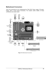
...Intel 865G Chipset ` 8 9 Front Panel Connectors 1 Configuration Jumper 1 Chassis Intrusion 1 FAN Front Chassis PSU ATX 12V PGA 478 Socket 1 CPU FAN 20 11 10 Power Connector 1 2 31 15 Floppy Drive 33 Connector 2 20 40 1 PCI IDE Connector x2 39 bb Figure 13: Motherboard Connectors D865GLC Motherboard Manual 38 Motherboard... Connectors There are shown below. The location and/or details of these connections are connectors on the motherboard for FAN, IDE, Power supply, CD audio, Floppy,...
...Intel 865G Chipset ` 8 9 Front Panel Connectors 1 Configuration Jumper 1 Chassis Intrusion 1 FAN Front Chassis PSU ATX 12V PGA 478 Socket 1 CPU FAN 20 11 10 Power Connector 1 2 31 15 Floppy Drive 33 Connector 2 20 40 1 PCI IDE Connector x2 39 bb Figure 13: Motherboard Connectors D865GLC Motherboard Manual 38 Motherboard... Connectors There are shown below. The location and/or details of these connections are connectors on the motherboard for FAN, IDE, Power supply, CD audio, Floppy,...

Manual
Page 68
D865GLC Motherboard Manual 67 Advanced BIOS SETUP UTILITY Peripheral Configuration Serial Port A Parallel Port Mode [Auto] [Auto] [Bi-directional] Audio Device Onboard LAN [Enabled] [Enabled] ←→ ↑↓ Tab Enter F1 F9 F10 ESC Select Menu Select Item Select Field Select sub-menu General ...
D865GLC Motherboard Manual 67 Advanced BIOS SETUP UTILITY Peripheral Configuration Serial Port A Parallel Port Mode [Auto] [Auto] [Bi-directional] Audio Device Onboard LAN [Enabled] [Enabled] ←→ ↑↓ Tab Enter F1 F9 F10 ESC Select Menu Select Item Select Field Select sub-menu General ...
Manual
Page 69
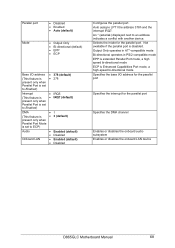
... operates in PS/2 compatible mode EPP is extended Parallel Port mode, a high speed bi-directional mode ECP is disabled. An * (asterisk) displayed next to ECP) Audio • Enabled (default) • Disabled Onboard LAN • Enabled (default) • Disabled Configures the parallel port. Parallel port Mode • Disabled • Enabled ... Specifies the interrupt for the parallel port. Selects the mode for the parallel port Specifies the DMA channel Enables or disables the onboard audio subsystem Enables or disables the onboard LAN device D865GLC Motherboard Manual 68
... operates in PS/2 compatible mode EPP is extended Parallel Port mode, a high speed bi-directional mode ECP is disabled. An * (asterisk) displayed next to ECP) Audio • Enabled (default) • Disabled Onboard LAN • Enabled (default) • Disabled Configures the parallel port. Parallel port Mode • Disabled • Enabled ... Specifies the interrupt for the parallel port. Selects the mode for the parallel port Specifies the DMA channel Enables or disables the onboard audio subsystem Enables or disables the onboard LAN device D865GLC Motherboard Manual 68

Manual
Page 96
D865GLC Motherboard Manual 95 Connector Signal Details Table 45: Wake on Ring Connector Pin Signal Name 1 Ground 2 RINGA# Table 46: Wake on LAN Connector Pin Signal Name 1 +5 ... Signal Name 1 Left Line In 2 Ground 3 Ground 4 Right Line In (monaural) Table 49: Telephony Connector Pin Signal Name 1 Audio in (monaural) 2 Ground 3 Ground 4 Mic pre-amp out (to modem) Table 50: CD Audio Connector Pin Signal Name 1 CD_IN-Left 2 Ground 3 Ground 4 CD_IN-Right Table 51: Chassis Intrusion Connector Pin Signal Name 1 Ground...
D865GLC Motherboard Manual 95 Connector Signal Details Table 45: Wake on Ring Connector Pin Signal Name 1 Ground 2 RINGA# Table 46: Wake on LAN Connector Pin Signal Name 1 +5 ... Signal Name 1 Left Line In 2 Ground 3 Ground 4 Right Line In (monaural) Table 49: Telephony Connector Pin Signal Name 1 Audio in (monaural) 2 Ground 3 Ground 4 Mic pre-amp out (to modem) Table 50: CD Audio Connector Pin Signal Name 1 CD_IN-Left 2 Ground 3 Ground 4 CD_IN-Right Table 51: Chassis Intrusion Connector Pin Signal Name 1 Ground...

Manual
Page 100
... 64: Audio Line Out Connector Pin Signal Name Sleeve Ground Tip Audio Left Out Ring Audio Right Out Table 65: Audio Line In Connector Pin Signal Name Sleeve Ground Tip Audio Left In Ring Audio Right In Table 66: Audio Mic In Connector Pin Signal Name Sleeve Ground Tip Mono In Ring Electret Bias Voltage D865GLC Motherboard Manual 99
... 64: Audio Line Out Connector Pin Signal Name Sleeve Ground Tip Audio Left Out Ring Audio Right Out Table 65: Audio Line In Connector Pin Signal Name Sleeve Ground Tip Audio Left In Ring Audio Right In Table 66: Audio Mic In Connector Pin Signal Name Sleeve Ground Tip Mono In Ring Electret Bias Voltage D865GLC Motherboard Manual 99

Manual
Page 102
...not currently implemented. or 16-bits 5 16-bits 6 16-bits 7 16-bits System Resource Open Parallel port Floppy drive Parallel port (for ECP)/audio Reserved - Motherboard Resources Table 70: Typical Memory Map Address Range Address Range (hex) (decimal) 1024 K - 393216 K 100000 - 18000000 928 K - 1024 K...controller Real time clock controller DMA page registers Interrupt controller 2 APM control DMA 2 Numeric processor Secondary IDE controller Primary IDE controller D865GLC Motherboard Manual 101 FFFFF 896 K - 928 K E0000 - C7FFF 00000 - 7FFFF Size 383 MB 96 KB 32 KB 96 KB...
...not currently implemented. or 16-bits 5 16-bits 6 16-bits 7 16-bits System Resource Open Parallel port Floppy drive Parallel port (for ECP)/audio Reserved - Motherboard Resources Table 70: Typical Memory Map Address Range Address Range (hex) (decimal) 1024 K - 393216 K 100000 - 18000000 928 K - 1024 K...controller Real time clock controller DMA page registers Interrupt controller 2 APM control DMA 2 Numeric processor Secondary IDE controller Primary IDE controller D865GLC Motherboard Manual 101 FFFFF 896 K - 928 K E0000 - C7FFF 00000 - 7FFFF Size 383 MB 96 KB 32 KB 96 KB...


