

Product Guide
Page 2
... will not occur in a residential installation. The D850MD and D850MV desktop boards may contain design defects or errors known as the property of this equipment does cause harmful interference to an outlet on request. Intel and Pentium are not designed, intended or authorized .... This equipment generates, uses, and can be claimed as errata which the failure of the Intel® Desktop Boards D850MD and D850MV Product Guide. If this product, contact: Intel Corporation 5200 N.E. All Rights Reserved. Current characterized errata are designed to obtain the latest specifications ...
... will not occur in a residential installation. The D850MD and D850MV desktop boards may contain design defects or errors known as the property of this equipment does cause harmful interference to an outlet on request. Intel and Pentium are not designed, intended or authorized .... This equipment generates, uses, and can be claimed as errata which the failure of the Intel® Desktop Boards D850MD and D850MV Product Guide. If this product, contact: Intel Corporation 5200 N.E. All Rights Reserved. Current characterized errata are designed to obtain the latest specifications ...

Product Guide
Page 4
Intel Desktop Boards D850MD and D850MV Product Guide Installing and Removing an AGP Card Retention Mechanism and Card 32 Installing the AGP Card Retention Mechanism 32 Installing an AGP Card 34 ... 59 Security Menu ...60 Power Menu ...61 APM Submenu ...62 ACPI Submenu...62 Boot Menu...63 Boot Device Priority 63 Exit Menu ...64 5 Technical Reference Board Connectors ...65 Back Panel Connectors 66 Midboard Connectors 67 Audio Connectors 67 Power and Hardware Connectors 68 Add-In Card and Peripheral Interface Connectors 70...
Intel Desktop Boards D850MD and D850MV Product Guide Installing and Removing an AGP Card Retention Mechanism and Card 32 Installing the AGP Card Retention Mechanism 32 Installing an AGP Card 34 ... 59 Security Menu ...60 Power Menu ...61 APM Submenu ...62 ACPI Submenu...62 Boot Menu...63 Boot Device Priority 63 Exit Menu ...64 5 Technical Reference Board Connectors ...65 Back Panel Connectors 66 Midboard Connectors 67 Audio Connectors 67 Power and Hardware Connectors 68 Add-In Card and Peripheral Interface Connectors 70...

Product Guide
Page 5
... 25 8. Contents Desktop Board Resources 73 Memory Map ...73 DMA Channels ...73 I /O Shield 22 5. D850MV Board Components 10 3. D850MV Board Mounting Screw Holes 24 7. Installing a Memory Module 31 14. D850MV Board Power and Hardware Control Connectors 69 25. Location of Standby Power Indicator 19 4. RDRAM and CRIMM Installation 29 12. Removing the Battery 41 21. D850MD Board Add-in Card...
... 25 8. Contents Desktop Board Resources 73 Memory Map ...73 DMA Channels ...73 I /O Shield 22 5. D850MV Board Components 10 3. D850MV Board Mounting Screw Holes 24 7. Installing a Memory Module 31 14. D850MV Board Power and Hardware Control Connectors 69 25. Location of Standby Power Indicator 19 4. RDRAM and CRIMM Installation 29 12. Removing the Battery 41 21. D850MD Board Add-in Card...

Product Guide
Page 6
... Security Menu...60 21. APM Submenu...62 23. Interrupts ...76 31. Front Panel Connectors 72 Tables 1. Processors Supported by the Desktop Board 11 3. Maintenance Menu ...48 9. IDE Configuration Submenu 56 16. Video Configuration Submenu 59 20. System Memory Map 73 28. ... Device Priority ...63 26. Safety Regulations...81 34. Standby Current Requirements 20 5. PCI Configuration Submenu 52 13. D850MV Board Add-in Card and Peripheral Interface Connectors 71 27. Peripheral Configuration Submenu 54 15. Intel Desktop Boards D850MD and D850MV Product Guide 26.
... Security Menu...60 21. APM Submenu...62 23. Interrupts ...76 31. Front Panel Connectors 72 Tables 1. Processors Supported by the Desktop Board 11 3. Maintenance Menu ...48 9. IDE Configuration Submenu 56 16. Video Configuration Submenu 59 20. System Memory Map 73 28. ... Device Priority ...63 26. Safety Regulations...81 34. Standby Current Requirements 20 5. PCI Configuration Submenu 52 13. D850MV Board Add-in Card and Peripheral Interface Connectors 71 27. Peripheral Configuration Submenu 54 15. Intel Desktop Boards D850MD and D850MV Product Guide 26.

Product Guide
Page 7
...Desktop Board Features ✏ NOTE The D850MD board layout was used for up to the optional CNR • Two IDE interfaces with Ultra DMA-33 and ATA-66/100 support • One floppy drive interface • One parallel port • Two serial ports • PS/2† keyboard and mouse ports D850MD board...Feature Summary Form Factors Processor Memory Chipset • microATX at 9.6 inches by 9.6 inches (D850MD board) • ATX at 9.6 inches by 12 inches (D850MV board) • Support for an Intel® Pentium® 4 processor in card connectors • One AGP connector • One...
...Desktop Board Features ✏ NOTE The D850MD board layout was used for up to the optional CNR • Two IDE interfaces with Ultra DMA-33 and ATA-66/100 support • One floppy drive interface • One parallel port • Two serial ports • PS/2† keyboard and mouse ports D850MD board...Feature Summary Form Factors Processor Memory Chipset • microATX at 9.6 inches by 9.6 inches (D850MD board) • ATX at 9.6 inches by 12 inches (D850MV board) • Support for an Intel® Pentium® 4 processor in card connectors • One AGP connector • One...

Product Guide
Page 8
Feature Summary (continued) BIOS • Intel/AMI BIOS • 4 Mbit symmetrical flash memory • Support for SMBIOS Power Management • Support for Advanced Configuration and Power Interface... • SCSI hard drive activity LED connector for the front panel • Speaker ✏ NOTE For information about Intel® desktop boards, including technical product specifications, BIOS updates, and device drivers, go to the Intel World Wide Web site at: http://support.intel.com/support/motherboards/desktop 8 Intel Desktop Boards D850MD and D850MV Product Guide Table 1.
Feature Summary (continued) BIOS • Intel/AMI BIOS • 4 Mbit symmetrical flash memory • Support for SMBIOS Power Management • Support for Advanced Configuration and Power Interface... • SCSI hard drive activity LED connector for the front panel • Speaker ✏ NOTE For information about Intel® desktop boards, including technical product specifications, BIOS updates, and device drivers, go to the Intel World Wide Web site at: http://support.intel.com/support/motherboards/desktop 8 Intel Desktop Boards D850MD and D850MV Product Guide Table 1.

Product Guide
Page 10
Intel Desktop Boards D850MD and D850MV Product Guide Figure 2 shows the location of the major components on the D850MV board. D850MV Board Components 10 A B CD E F G CC H I BB J AA K L Z Y X M W V TR US P Q O N OM12073 A ADI AD1885 audio codec P Primary IDE ... connector W Speaker I Processor fan connector (CPU fan) (tachometer input) X BIOS configuration jumper J Intel 82850 Memory Controller Hub (MCH) Y SCSI hard drive activity LED connector K Processor socket Z Intel 82801BA I/O Controller Hub (ICH2) L RIMM sockets AA PCI bus add-in card connectors M RIMM ...
Intel Desktop Boards D850MD and D850MV Product Guide Figure 2 shows the location of the major components on the D850MV board. D850MV Board Components 10 A B CD E F G CC H I BB J AA K L Z Y X M W V TR US P Q O N OM12073 A ADI AD1885 audio codec P Primary IDE ... connector W Speaker I Processor fan connector (CPU fan) (tachometer input) X BIOS configuration jumper J Intel 82850 Memory Controller Hub (MCH) Y SCSI hard drive activity LED connector K Processor socket Z Intel 82801BA I/O Controller Hub (ICH2) L RIMM sockets AA PCI bus add-in card connectors M RIMM ...
Product Guide
Page 11
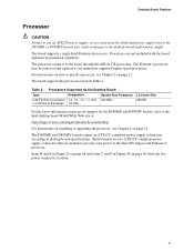
... Pentium 4 processor may result in a mPGA-478 package 1.8 GHz L2 Cache Size 256 KB For the latest information on processor support for the D850MD and D850MV boards, refer to the Intel desktop board World Wide Web site at: http://support.intel.com/support/motherboards/desktop For instructions on installing or upgrading the processor, see Chapter 2 on page 21. The...
... Pentium 4 processor may result in a mPGA-478 package 1.8 GHz L2 Cache Size 256 KB For the latest information on processor support for the D850MD and D850MV boards, refer to the Intel desktop board World Wide Web site at: http://support.intel.com/support/motherboards/desktop For instructions on installing or upgrading the processor, see Chapter 2 on page 21. The...

Product Guide
Page 12
...) memory only ✏ NOTE For information about vendors that support RIMMs containing Direct Rambus DRAM (RDRAM) devices. Intel Desktop Boards D850MD and D850MV Product Guide Main Memory The board has four 2.5 V memory module sockets that support these features: • Integrated dual Direct Rambus technology memory channel...• Auto-detection of 32 RDRAM devices per channel • 128 MB (minimum) to the D850MD or D850MV link on this Intel World Wide Web site: http://support.intel.com/support/motherboards/desktop For information about installing memory, see Chapter 2 on page 21.
...) memory only ✏ NOTE For information about vendors that support RIMMs containing Direct Rambus DRAM (RDRAM) devices. Intel Desktop Boards D850MD and D850MV Product Guide Main Memory The board has four 2.5 V memory module sockets that support these features: • Integrated dual Direct Rambus technology memory channel...• Auto-detection of 32 RDRAM devices per channel • 128 MB (minimum) to the D850MD or D850MV link on this Intel World Wide Web site: http://support.intel.com/support/motherboards/desktop For information about installing memory, see Chapter 2 on page 21.

Product Guide
Page 14
...Mode 3 and PIO Mode 4 devices • Ultra DMA-33 and ATA-66/100 protocol • Laser servo (LS-120) drives Expansion Slots The D850MD board has: • Three PCI bus add-in card connectors (PCI bus connector 3 slot shared with CNR) • One AGP connector • One optional...• Five PCI bus add-in ports. To attach additional devices, connect an external hub to seven USB ports; Intel Desktop Boards D850MD and D850MV Product Guide USB Support The boards suppport up to either of information between the processor and peripheral devices like hard disks, CD-ROM drives, and Iomega ...
...Mode 3 and PIO Mode 4 devices • Ultra DMA-33 and ATA-66/100 protocol • Laser servo (LS-120) drives Expansion Slots The D850MD board has: • Three PCI bus add-in card connectors (PCI bus connector 3 slot shared with CNR) • One AGP connector • One optional...• Five PCI bus add-in ports. To attach additional devices, connect an external hub to seven USB ports; Intel Desktop Boards D850MD and D850MV Product Guide USB Support The boards suppport up to either of information between the processor and peripheral devices like hard disks, CD-ROM drives, and Iomega ...

Product Guide
Page 16
... device for a password. A supervisor password and a user password can be accessed and who can boot the computer. If only the supervisor password is booted. Intel Desktop Boards D850MD and D850MV Product Guide IDE Auto Configuration If you can enter either the supervisor password or the user password to view and change all Setup options. Setup...
... device for a password. A supervisor password and a user password can be accessed and who can boot the computer. If only the supervisor password is booted. Intel Desktop Boards D850MD and D850MV Product Guide IDE Auto Configuration If you can enter either the supervisor password or the user password to view and change all Setup options. Setup...
Product Guide
Page 17
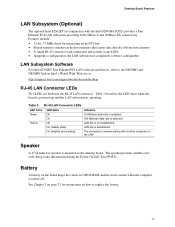
... Power-On Self-Test (POST). Speaker A 47 Ω inductive speaker is mounted on how to the D850MD and D850MV link on the LAN. Desktop Board Features LAN Subsystem (Optional) The optional Intel 82562ET (in CMOS RAM and the clock current when the computer is turned off. the LAN subsystem is ...17 Features include: • 32-bit, 33-MHz direct bus mastering on the board keeps the values in conjunction with another computer on Intel's World Wide Web site at: http://support.intel.com/support/motherboards/desktop RJ-45 LAN Connector LEDs Two LEDs are built into the RJ-45 LAN connector....
... Power-On Self-Test (POST). Speaker A 47 Ω inductive speaker is mounted on how to the D850MD and D850MV link on the LAN. Desktop Board Features LAN Subsystem (Optional) The optional Intel 82562ET (in CMOS RAM and the clock current when the computer is turned off. the LAN subsystem is ...17 Features include: • 32-bit, 33-MHz direct bus mastering on the board keeps the values in conjunction with another computer on Intel's World Wide Web site at: http://support.intel.com/support/motherboards/desktop RJ-45 LAN Connector LEDs Two LEDs are built into the RJ-45 LAN connector....

Product Guide
Page 18
...ACPI S3 sleep state functionality. This includes the memory modules and PCI bus connectors even when the computer appears to be off . Intel Desktop Boards D850MD and D850MV Product Guide Power Management Features Power management is implemented at several levels, including: • Software support: Advanced Configuration and... Resume on Ring Wake from USB Wake from the PCI and/or USB buses exceeds power supply capacity, the desktop board may lose register settings stored in memory. When signaled by the LED turning amber. 18 Otherwise, it defaults to -RAM) sleep ...
...ACPI S3 sleep state functionality. This includes the memory modules and PCI bus connectors even when the computer appears to be off . Intel Desktop Boards D850MD and D850MV Product Guide Power Management Features Power management is implemented at several levels, including: • Software support: Advanced Configuration and... Resume on Ring Wake from USB Wake from the PCI and/or USB buses exceeds power supply capacity, the desktop board may lose register settings stored in memory. When signaled by the LED turning amber. 18 Otherwise, it defaults to -RAM) sleep ...
Product Guide
Page 19
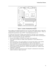
... the total PS/2 port standby current requirement if a wake-enabled device is connected. 3. Add to the descriptions in Table 4. Note the total D850MD or D850MV board standby current requirement. 2. Add all additional wake-enabled devices' and non-wake-enabled devices' standby current requirements as outlined in Table 4 on page... all the required current totals from steps 1 through 5 to support the standard Instantly Available (ACPI S3 sleep state) configuration as applicable. 6. Desktop Board Features CR7F1 OM11834 Figure 3. Add all installed components must be added.
... the total PS/2 port standby current requirement if a wake-enabled device is connected. 3. Add to the descriptions in Table 4. Note the total D850MD or D850MV board standby current requirement. 2. Add all additional wake-enabled devices' and non-wake-enabled devices' standby current requirements as outlined in Table 4 on page... all the required current totals from steps 1 through 5 to support the standard Instantly Available (ACPI S3 sleep state) configuration as applicable. 6. Desktop Board Features CR7F1 OM11834 Figure 3. Add all installed components must be added.
Product Guide
Page 20
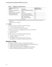
Intel Desktop Boards D850MD and D850MV Product Guide Table 4. Resume on Ring The operation of 700 mA. wake-enabled ...system configuration ✏ NOTE PCI requirements are limited to a combined total of Resume on components (Add to integrated board components shown above) Description Total for the D850MD or D850MV boards PS/2 ports** PCI 2.2 slots (wake-enabled) PCI 2.2 slots (non-wake-enabled) CNR** (wake enabled... mode or the ACPI S1 state • Requires only one call to the Intel® Desktop Board D850MV/D850MD Technical Product Specification for correct operation 20
Intel Desktop Boards D850MD and D850MV Product Guide Table 4. Resume on Ring The operation of 700 mA. wake-enabled ...system configuration ✏ NOTE PCI requirements are limited to a combined total of Resume on components (Add to integrated board components shown above) Description Total for the D850MD or D850MV boards PS/2 ports** PCI 2.2 slots (wake-enabled) PCI 2.2 slots (non-wake-enabled) CNR** (wake enabled... mode or the ACPI S1 state • Requires only one call to the Intel® Desktop Board D850MV/D850MD Technical Product Specification for correct operation 20
Product Guide
Page 22
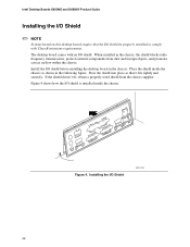
.... When installed in the chassis. Install the I/O shield before installing the desktop board in the chassis, the shield blocks radio frequency transmissions, protects internal components from the chassis supplier. Intel Desktop Boards D850MD and D850MV Product Guide Installing the I/O Shield ✏ NOTE Systems based on this desktop board require that it fits tightly and securely. Figure 4 shows how the...
.... When installed in the chassis. Install the I/O shield before installing the desktop board in the chassis, the shield blocks radio frequency transmissions, protects internal components from the chassis supplier. Intel Desktop Boards D850MD and D850MV Product Guide Installing the I/O Shield ✏ NOTE Systems based on this desktop board require that it fits tightly and securely. Figure 4 shows how the...

Product Guide
Page 23
... screws and the D850MV board by qualified technical personnel. Disconnect the computer from its power source before you open the computer can result in personal injury or equipment damage. ✏ NOTES You will need a Phillips† (#2 bit) screwdriver. D850MD Board Mounting Screw Holes 23 Installing and Replacing Desktop Board Components Installing and Removing the Desktop Board Refer to...
... screws and the D850MV board by qualified technical personnel. Disconnect the computer from its power source before you open the computer can result in personal injury or equipment damage. ✏ NOTES You will need a Phillips† (#2 bit) screwdriver. D850MD Board Mounting Screw Holes 23 Installing and Replacing Desktop Board Components Installing and Removing the Desktop Board Refer to...

Product Guide
Page 24
OM12178 Figure 6. Intel Desktop Boards D850MD and D850MV Product Guide Figure 6 shows the location of the mounting holes for the D850MV board. D850MV Board Mounting Screw Holes 24
OM12178 Figure 6. Intel Desktop Boards D850MD and D850MV Product Guide Figure 6 shows the location of the mounting holes for the D850MV board. D850MV Board Mounting Screw Holes 24
Product Guide
Page 26
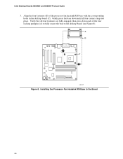
Installing the Processor Fan Heatsink RM Base to the desktop board (see Figure 8). A B C OM12177 Figure 8. Gently press the base down each of the processor fan heatsink RM base with the corresponding holes in the desktop board (C). Intel Desktop Boards D850MD and D850MV Product Guide 3. Verify that all four fasteners are fully engaged, then press down until all four corners snap into place. Align the four fasteners (B) of the four locking pushpins (A) to fully secure the base to the Board 26
Installing the Processor Fan Heatsink RM Base to the desktop board (see Figure 8). A B C OM12177 Figure 8. Gently press the base down each of the processor fan heatsink RM base with the corresponding holes in the desktop board (C). Intel Desktop Boards D850MD and D850MV Product Guide 3. Verify that all four fasteners are fully engaged, then press down until all four corners snap into place. Align the four fasteners (B) of the four locking pushpins (A) to fully secure the base to the Board 26
Product Guide
Page 28
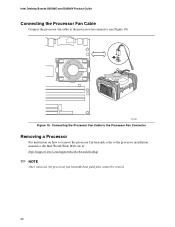
OM12083 Figure 10. Intel Desktop Boards D850MD and D850MV Product Guide Connecting the Processor Fan Cable Connect the processor fan cable to the processor installation manual or the Intel World Wide Web site at: http://support.intel.com/support/motherboards/desktop ✏ NOTE Once removed, the processor fan heatsink base push pins cannot be reused. 28 Connecting the Processor Fan Cable to the Processor Fan Connector Removing a Processor For instruction on how to remove the processor fan heatsink, refer to the processor fan connector (see Figure 10).
OM12083 Figure 10. Intel Desktop Boards D850MD and D850MV Product Guide Connecting the Processor Fan Cable Connect the processor fan cable to the processor installation manual or the Intel World Wide Web site at: http://support.intel.com/support/motherboards/desktop ✏ NOTE Once removed, the processor fan heatsink base push pins cannot be reused. 28 Connecting the Processor Fan Cable to the Processor Fan Connector Removing a Processor For instruction on how to remove the processor fan heatsink, refer to the processor fan connector (see Figure 10).
