
Product Guide
Page 3
Contents 1 Desktop Board Features Desktop Board Components 9 Processor ...11 Main Memory ...12 Intel® 850E Chipset ...12 Intel® 82850E Memory Controller Hub (MCH 12 Intel® 82801BA I/O Controller Hub (ICH2 13 Firmware Hub (FWH 13 Input/Output (I/O) Controller 13 ... Resume on Ring...20 2 Installing and Replacing Desktop Board Components Before You Begin ...21 Installing the I/O Shield ...22 Installing and Removing the Desktop Board 22 Installing a Processor ...24 Removing the Processor ...25 Installing Memory ...25 Removing Memory ...27 Installing an AGP Card...28 Removing the...
Contents 1 Desktop Board Features Desktop Board Components 9 Processor ...11 Main Memory ...12 Intel® 850E Chipset ...12 Intel® 82850E Memory Controller Hub (MCH 12 Intel® 82801BA I/O Controller Hub (ICH2 13 Firmware Hub (FWH 13 Input/Output (I/O) Controller 13 ... Resume on Ring...20 2 Installing and Replacing Desktop Board Components Before You Begin ...21 Installing the I/O Shield ...22 Installing and Removing the Desktop Board 22 Installing a Processor ...24 Removing the Processor ...25 Installing Memory ...25 Removing Memory ...27 Installing an AGP Card...28 Removing the...
Product Guide
Page 4
Intel Desktop Boards D850EMD2 and D850EMV2 Product Guide 3 Updating the BIOS Updating the BIOS with the Intel® Express BIOS Update Utility 35 Updating the BIOS with the Intel® Flash Memory Update Utility 35 Obtaining the BIOS Update File 35 Updating the BIOS...36 Recovering the BIOS ...Connectors 59 Audio Connectors 59 Power and Hardware Connectors 60 Add-In Card and Peripheral Interface Connectors 62 Front Panel Connectors 64 Desktop Board Resources 65 Memory Map ...65 DMA Channels ...65 I/O Map ...66 Interrupts ...68 A Error Messages and Indicators BIOS Beep Codes ...69 BIOS...
Intel Desktop Boards D850EMD2 and D850EMV2 Product Guide 3 Updating the BIOS Updating the BIOS with the Intel® Express BIOS Update Utility 35 Updating the BIOS with the Intel® Flash Memory Update Utility 35 Obtaining the BIOS Update File 35 Updating the BIOS...36 Recovering the BIOS ...Connectors 59 Audio Connectors 59 Power and Hardware Connectors 60 Add-In Card and Peripheral Interface Connectors 62 Front Panel Connectors 64 Desktop Board Resources 65 Memory Map ...65 DMA Channels ...65 I/O Map ...66 Interrupts ...68 A Error Messages and Indicators BIOS Beep Codes ...69 BIOS...
Product Guide
Page 5
...14. Removing the Battery...34 16. RJ-45 LAN Connector LEDs 17 4. Location of the Standby Power Indicator 18 4. Desktop Board D850EMV2 Power and Hardware Control Connectors 61 20. Maintenance Menu ...40 9. Advanced Menu ...43 12. Contents EMC Regulations ...... Setup Program Modes (J9H2 30 6. Installing a Processor...24 8. Installing a Memory Module 27 12. Desktop Board D850EMV2 Mounting Screw Holes 23 7. RIMM Installation ...26 11. Main Menu ...42 11. Desktop Board D850EMD2 Components 9 2. Location of the BIOS Configuration Jumper 30 15. Extended ...
...14. Removing the Battery...34 16. RJ-45 LAN Connector LEDs 17 4. Location of the Standby Power Indicator 18 4. Desktop Board D850EMV2 Power and Hardware Control Connectors 61 20. Maintenance Menu ...40 9. Advanced Menu ...43 12. Contents EMC Regulations ...... Setup Program Modes (J9H2 30 6. Installing a Processor...24 8. Installing a Memory Module 27 12. Desktop Board D850EMV2 Mounting Screw Holes 23 7. RIMM Installation ...26 11. Main Menu ...42 11. Desktop Board D850EMD2 Components 9 2. Location of the BIOS Configuration Jumper 30 15. Extended ...
Product Guide
Page 7
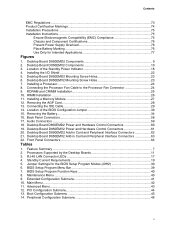
... system memory Intel® 850E chipset, consisting of the Desktop Boards D850EMD2 and D850EMV2. Table 1. Feature Summary Form Factors Processor Memory Chipset • microATX at 9.6 inches by 9.6 inches (D850EMD2 board) • ATX at 9.6 inches by 12 inches (D850EMV2 board) • Support for an Intel®...Table 1 describes the major features of : I/O Control • Intel® 82850E Memory Controller Hub (MCH) with Accelerated Hub Architecture (AHA) bus • Intel® 82801BA I /O controller LAN Optional Intel® 82562ET 10/100 Mbit/sec Platform LAN Connect (PLC) ...
... system memory Intel® 850E chipset, consisting of the Desktop Boards D850EMD2 and D850EMV2. Table 1. Feature Summary Form Factors Processor Memory Chipset • microATX at 9.6 inches by 9.6 inches (D850EMD2 board) • ATX at 9.6 inches by 12 inches (D850EMV2 board) • Support for an Intel®...Table 1 describes the major features of : I/O Control • Intel® 82850E Memory Controller Hub (MCH) with Accelerated Hub Architecture (AHA) bus • Intel® 82801BA I /O controller LAN Optional Intel® 82562ET 10/100 Mbit/sec Platform LAN Connect (PLC) ...
Product Guide
Page 8
Intel Desktop Boards D850EMD2 and D850EMV2 Product Guide Table 1. Feature Summary (continued) BIOS • Intel/AMI BIOS • 4 Mbit symmetrical flash memory • Support for SMBIOS Power Management • Support for Advanced Configuration and Power Interface (ACPI 1.0) •... drive activity LED connector for the front panel • Speaker ✏ NOTE For information about Intel® desktop boards, including technical product specifications, BIOS updates, and device drivers, go to the Intel World Wide Web site at: http://support.intel.com/support/motherboards/desktop 8
Intel Desktop Boards D850EMD2 and D850EMV2 Product Guide Table 1. Feature Summary (continued) BIOS • Intel/AMI BIOS • 4 Mbit symmetrical flash memory • Support for SMBIOS Power Management • Support for Advanced Configuration and Power Interface (ACPI 1.0) •... drive activity LED connector for the front panel • Speaker ✏ NOTE For information about Intel® desktop boards, including technical product specifications, BIOS updates, and device drivers, go to the Intel World Wide Web site at: http://support.intel.com/support/motherboards/desktop 8

Product Guide
Page 10
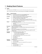
Intel Desktop Boards D850EMD2 and D850EMV2 Product Guide Figure 2 shows the location of the major components on the Desktop Board D850EMV2. A B CD E F G DD H I CC J BB K AA L Z Y X M W ...Memory Controller Hub (MCH) Z Intel 82801BA I/O Controller Hub (ICH2) K Processor socket AA NEC D720100AGM USB 2.0 controller L RIMM sockets BB PCI bus add-in card connectors M RIMM fan connector (fan 1) CC Communication and Networking Riser (CNR) (optional) N Power connector DD Chassis fan connector (fan 3) O Floppy drive connector P Primary IDE connector Figure 2. Desktop Board...
Intel Desktop Boards D850EMD2 and D850EMV2 Product Guide Figure 2 shows the location of the major components on the Desktop Board D850EMV2. A B CD E F G DD H I CC J BB K AA L Z Y X M W ...Memory Controller Hub (MCH) Z Intel 82801BA I/O Controller Hub (ICH2) K Processor socket AA NEC D720100AGM USB 2.0 controller L RIMM sockets BB PCI bus add-in card connectors M RIMM fan connector (fan 1) CC Communication and Networking Riser (CNR) (optional) N Power connector DD Chassis fan connector (fan 3) O Floppy drive connector P Primary IDE connector Figure 2. Desktop Board...

Product Guide
Page 12
...-ECC support ✏ NOTE For information about installing memory, see Chapter 2 on this Intel World Wide Web site: http://support.intel.com/support/motherboards/desktop For information about vendors that support RIMMs containing Direct Rambus DRAM (RDRAM) devices. Intel Desktop Boards D850EMD2 and D850EMV2 Product Guide Main Memory The desktop boards have four 2.5 V memory module sockets that support these features: • Integrated...
...-ECC support ✏ NOTE For information about installing memory, see Chapter 2 on this Intel World Wide Web site: http://support.intel.com/support/motherboards/desktop For information about vendors that support RIMMs containing Direct Rambus DRAM (RDRAM) devices. Intel Desktop Boards D850EMD2 and D850EMV2 Product Guide Main Memory The desktop boards have four 2.5 V memory module sockets that support these features: • Integrated...
Product Guide
Page 16
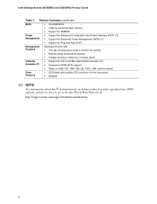
...passwords are then available for viewing and changing depending on the PCI bus • Shared memory structure in the host memory that copies data directly to/from host memory • A single RJ-45 connector with connection and activity status LEDs • Jumperless ...for your computer. LAN Subsystem (Optional) The optional Intel 82562ET (in conjunction with the following items are set , pressing at : http://support.intel.com/support/motherboards/desktop 16 If both 10Base-T and 100Base-TX connectivity. Intel Desktop Boards D850EMD2 and D850EMV2 Product Guide IDE Auto Configuration If...
...passwords are then available for viewing and changing depending on the PCI bus • Shared memory structure in the host memory that copies data directly to/from host memory • A single RJ-45 connector with connection and activity status LEDs • Jumperless ...for your computer. LAN Subsystem (Optional) The optional Intel 82562ET (in conjunction with the following items are set , pressing at : http://support.intel.com/support/motherboards/desktop 16 If both 10Base-T and 100Base-TX connectivity. Intel Desktop Boards D850EMD2 and D850EMV2 Product Guide IDE Auto Configuration If...

Product Guide
Page 18
...) sleep state. Values are determined by the LED turning amber. Actual measurements may lose register settings stored in memory. Instantly Available technology enables the desktop board to enter the ACPI S3 (Suspend-to the system. If the system has a dual-colored power LED on... standby current necessary to support multiple wake events from the PCI and/or USB buses exceeds power supply capacity, the desktop board may vary. 18 Intel Desktop Boards D850EMD2 and D850EMV2 Product Guide Instantly Available Technology CAUTION For Instantly Available technology, the 5 V standby line for the...
...) sleep state. Values are determined by the LED turning amber. Actual measurements may lose register settings stored in memory. Instantly Available technology enables the desktop board to enter the ACPI S3 (Suspend-to the system. If the system has a dual-colored power LED on... standby current necessary to support multiple wake events from the PCI and/or USB buses exceeds power supply capacity, the desktop board may vary. 18 Intel Desktop Boards D850EMD2 and D850EMV2 Product Guide Instantly Available Technology CAUTION For Instantly Available technology, the 5 V standby line for the...
Product Guide
Page 21
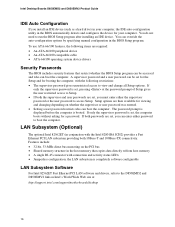
... can damage components. If such a station is off. 21 2 Installing and Replacing Desktop Board Components This chapter tells you how to: • Install the I/O shield • Install and remove the desktop board • Install and remove a processor • Install and remove memory • Install and remove an AGP card • Connect the IDE cable •...
... can damage components. If such a station is off. 21 2 Installing and Replacing Desktop Board Components This chapter tells you how to: • Install the I/O shield • Install and remove the desktop board • Install and remove a processor • Install and remove memory • Install and remove an AGP card • Connect the IDE cable •...
Product Guide
Page 25
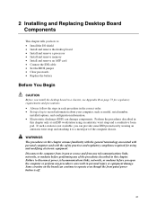
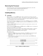
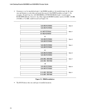
...memory connector or the desktop board will not boot. When adding memory: • Install a pair of sockets closest to the processor is for the location of RDRAM components installed in Figure 11. Failure to the processor installation manual or the Intel World Wide Web site at: http://support.intel.com/support/motherboards/desktop Installing Memory... CRIMM CRIMM Figure 9. Incorrect insertion of no more than 32 RDRAM components per RDRAM channel. The desktop board has four memory module sockets arranged as shown in all RIMM sockets exceeds 64, the computer will not boot. RDRAM...
...memory connector or the desktop board will not boot. When adding memory: • Install a pair of sockets closest to the processor is for the location of RDRAM components installed in Figure 11. Failure to the processor installation manual or the Intel World Wide Web site at: http://support.intel.com/support/motherboards/desktop Installing Memory... CRIMM CRIMM Figure 9. Incorrect insertion of no more than 32 RDRAM components per RDRAM channel. The desktop board has four memory module sockets arranged as shown in all RIMM sockets exceeds 64, the computer will not boot. RDRAM...
Product Guide
Page 26
Intel Desktop Boards D850EMD2 and D850EMV2 Product Guide • If memory is to be installed in bank 0. Bank 0 Bank 1 Bank 0 Bank 1 Bank 0 Bank 1 Bank 0 Bank 1 26 RIMM Installation • The BIOS detects the size and type of the RIMM modules in bank 1, the RIMM modules to each other and match the speed of installed memory. For...
Intel Desktop Boards D850EMD2 and D850EMV2 Product Guide • If memory is to be installed in bank 0. Bank 0 Bank 1 Bank 0 Bank 1 Bank 0 Bank 1 Bank 0 Bank 1 26 RIMM Installation • The BIOS detects the size and type of the RIMM modules in bank 1, the RIMM modules to each other and match the speed of installed memory. For...

Product Guide
Page 27
... on page 21. 2. Make sure the clips are pushed away from the AC power source (wall outlet or power adapter). 3. Hold the memory module by the edges, remove it from the socket, and store it away from its antistatic package. 3. Reinstall and reconnect any parts you...small notches in the bottom edge of the socket are firmly in the socket. 5. Installing and Replacing Desktop Board Components To install the memory modules, follow these steps (see Figure 11): 1. Holding the memory module by the edges, lift it in an antistatic package. 6. Insert the bottom edge of the...
... on page 21. 2. Make sure the clips are pushed away from the AC power source (wall outlet or power adapter). 3. Hold the memory module by the edges, remove it from the socket, and store it away from its antistatic package. 3. Reinstall and reconnect any parts you...small notches in the bottom edge of the socket are firmly in the socket. 5. Installing and Replacing Desktop Board Components To install the memory modules, follow these steps (see Figure 11): 1. Holding the memory module by the edges, lift it in an antistatic package. 6. Insert the bottom edge of the...
Product Guide
Page 32
... computer is accurate to ± 13 minutes/year at 25 ºC with an equivalent one. Intel Desktop Boards D850EMD2 and D850EMV2 Product Guide Replacing the Battery A coin-cell battery (CR2032) powers the real-time clock and CMOS memory. The clock is plugged in accordance with an incorrect type. Batteries should be accurate. Batterier bø...
... computer is accurate to ± 13 minutes/year at 25 ºC with an equivalent one. Intel Desktop Boards D850EMD2 and D850EMV2 Product Guide Replacing the Battery A coin-cell battery (CR2032) powers the real-time clock and CMOS memory. The clock is plugged in accordance with an incorrect type. Batteries should be accurate. Batterier bø...

Product Guide
Page 35
... Wide Web site: http://support.intel.com/support/motherboards/desktop 2. This step is useful if you need to complete the BIOS update. The BIOS update file is included in the dialog boxes to update the ... file. The BIOS update file contains: • New BIOS files • BIOS recovery files • Intel Flash Memory Update Utility 35 Download the file to a diskette. Close all the files you are updating the BIOS for the Desktop Boards D850EMV2 or D850EMD2 BIOS. 3. Follow the instructions provided in an automated update utility that will...
... Wide Web site: http://support.intel.com/support/motherboards/desktop 2. This step is useful if you need to complete the BIOS update. The BIOS update file is included in the dialog boxes to update the ... file. The BIOS update file contains: • New BIOS files • BIOS recovery files • Intel Flash Memory Update Utility 35 Download the file to a diskette. Close all the files you are updating the BIOS for the Desktop Boards D850EMV2 or D850EMD2 BIOS. 3. Follow the instructions provided in an automated update utility that will...
Product Guide
Page 36
...is complete, the monitor will interrupt the BIOS update; The Intel Flash Memory Update Utility allows you to remove the diskette and to reboot the system. 3. Recovering the BIOS It is no video support. Intel Desktop Boards D850EMD2 and D850EMV2 Product Guide You can obtain the BIOS update...the computer with the BIOS update diskette in the boot block area, there is unlikely that anything on the Intel World Wide Web site: http://support.intel.com/support/motherboards/desktop ✏ NOTE Please review the instructions distributed with the update files updates the BIOS. If a logo ...
...is complete, the monitor will interrupt the BIOS update; The Intel Flash Memory Update Utility allows you to remove the diskette and to reboot the system. 3. Recovering the BIOS It is no video support. Intel Desktop Boards D850EMD2 and D850EMV2 Product Guide You can obtain the BIOS update...the computer with the BIOS update diskette in the boot block area, there is unlikely that anything on the Intel World Wide Web site: http://support.intel.com/support/motherboards/desktop ✏ NOTE Please review the instructions distributed with the update files updates the BIOS. If a logo ...

Product Guide
Page 39
... the BIOS Setup program menu bar. For the latest BIOS settings, refer to the Intel Desktop Board D850EMD2/D850EMV2 Technical Product Specification or the Intel World Wide Web site: http://support.intel.com/support/motherboards/desktop ✏ NOTE For reference purposes, you make changes to the settings, update this record...the key after the Power-On Self-Test (POST) memory test begins and before the operating system boot begins. ✏ NOTE The BIOS Setup menus described in this section apply to the desktop boards with other BIOS identifiers might have differences in this section...
... the BIOS Setup program menu bar. For the latest BIOS settings, refer to the Intel Desktop Board D850EMD2/D850EMV2 Technical Product Specification or the Intel World Wide Web site: http://support.intel.com/support/motherboards/desktop ✏ NOTE For reference purposes, you make changes to the settings, update this record...the key after the Power-On Self-Test (POST) memory test begins and before the operating system boot begins. ✏ NOTE The BIOS Setup menus described in this section apply to the desktop boards with other BIOS identifiers might have differences in this section...
Product Guide
Page 42
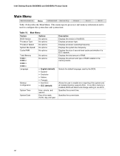
...used to non-ECC. Displays processor operating frequency. Allows the user to enable error reporting if the system and all installed memory supports ECC. Main Menu Feature BIOS Version Options No options Processor Type Processor Speed No options No options System Bus Speed ...and second Day of the week, month, day, and year Description Displays the version of RAM installed in the memory banks. Displays the system bus frequency. Intel Desktop Boards D850EMD2 and D850EMV2 Product Guide Main Menu Maintenance Main Advanced Security Power Boot Exit Table 10 describes the Main Menu...
...used to non-ECC. Displays processor operating frequency. Allows the user to enable error reporting if the system and all installed memory supports ECC. Main Menu Feature BIOS Version Options No options Processor Type Processor Speed No options No options System Bus Speed ...and second Day of the week, month, day, and year Description Displays the version of RAM installed in the memory banks. Displays the system bus frequency. Intel Desktop Boards D850EMD2 and D850EMV2 Product Guide Main Menu Maintenance Main Advanced Security Power Boot Exit Table 10 describes the Main Menu...

Product Guide
Page 56
... the Setup values from flash memory. If this memory is used . 56 The option values present when the computer was turned on are set, the BIOS reads the factory defaults. Exit Menu Feature Description Exit Saving Changes Exits and saves the changes made in the BIOS Setup program. Intel Desktop Boards D850EMD2 and D850EMV2 Product...
... the Setup values from flash memory. If this memory is used . 56 The option values present when the computer was turned on are set, the BIOS reads the factory defaults. Exit Menu Feature Description Exit Saving Changes Exits and saves the changes made in the BIOS Setup program. Intel Desktop Boards D850EMD2 and D850EMV2 Product...

Product Guide
Page 65
FFFFF E0000 - DFFFF 640 K - 800 K 639 K - 640 K A0000 - Technical Reference Desktop Board Resources Memory Map Table 27. EFFFF C8000 - System Memory Map Address Range (decimal) 1024 K - 2097152 K 960 K - 1024 K 896 K - 960 K 800 K - 896 K Address Range (hex) 100000 - 7FFFFFFF ... KB 1 KB 127 KB 512 KB Description Extended Memory Runtime BIOS Reserved Available high DOS memory (open to the PCI bus) Video memory and BIOS Extended BIOS data (movable by memory manager software) Extended conventional memory Conventional memory DMA Channels Table 28. DMA Channels DMA Channel Number...
FFFFF E0000 - DFFFF 640 K - 800 K 639 K - 640 K A0000 - Technical Reference Desktop Board Resources Memory Map Table 27. EFFFF C8000 - System Memory Map Address Range (decimal) 1024 K - 2097152 K 960 K - 1024 K 896 K - 960 K 800 K - 896 K Address Range (hex) 100000 - 7FFFFFFF ... KB 1 KB 127 KB 512 KB Description Extended Memory Runtime BIOS Reserved Available high DOS memory (open to the PCI bus) Video memory and BIOS Extended BIOS data (movable by memory manager software) Extended conventional memory Conventional memory DMA Channels Table 28. DMA Channels DMA Channel Number...

