Product Guide
Page 18
... password prompt is displayed before the computer is set , you can boot the computer. Suspend to access Setup. The use of ACPI with the following restrictions: • The supervisor password gives unrestricted access to boot the computer. Fan Connectors The desktop board has two chassis ...user password to RAM (Instantly Available PC technology) - See Figure 10 on page 34 for the location of a computer. Intel Desktop Board D845GVSR Product Guide Security Passwords The BIOS includes security features that restrict whether the BIOS Setup program can be accessed and who can be...
... password prompt is displayed before the computer is set , you can boot the computer. Suspend to access Setup. The use of ACPI with the following restrictions: • The supervisor password gives unrestricted access to boot the computer. Fan Connectors The desktop board has two chassis ...user password to RAM (Instantly Available PC technology) - See Figure 10 on page 34 for the location of a computer. Intel Desktop Board D845GVSR Product Guide Security Passwords The BIOS includes security features that restrict whether the BIOS Setup program can be accessed and who can be...
Product Guide
Page 37
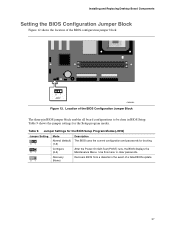
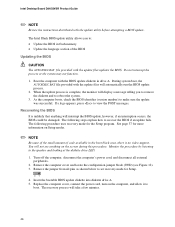
Installing and Replacing Desktop Board Components Setting the BIOS Configuration Jumper Block Figure 12 shows the location of the BIOS Configuration Jumper Block The three-pin BIOS jumper block enables all board configurations to clear passwords. 31 Recovery (None) Recovers BIOS from a diskette in BIOS Setup. Location of the BIOS configuration jumper block. 31... event of a failed BIOS update. 37 Table 9 shows the jumper settings for booting. 31 Configure (2-3) After the Power-On Self-Test (POST) runs, the BIOS displays the Maintenance Menu.
Installing and Replacing Desktop Board Components Setting the BIOS Configuration Jumper Block Figure 12 shows the location of the BIOS Configuration Jumper Block The three-pin BIOS jumper block enables all board configurations to clear passwords. 31 Recovery (None) Recovers BIOS from a diskette in BIOS Setup. Location of the BIOS configuration jumper block. 31... event of a failed BIOS update. 37 Table 9 shows the jumper settings for booting. 31 Configure (2-3) After the Power-On Self-Test (POST) runs, the BIOS displays the Maintenance Menu.
Product Guide
Page 38
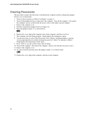
... computer cover. 12. Turn off the computer. Disconnect the computer's power cord from the AC power source. 11. Remove the computer cover. 4. Setup displays the maintenance menu again. 9. Disconnect the computer's power cord from the AC power source (wall outlet or power adapter). 3. Replace the cover, plug in..."Before You Begin" on the computer. 38 Turn off all peripheral devices connected to boot. 7. Find the configuration jumper block (see Figure 12). 5. Intel Desktop Board D845GVSR Product Guide Clearing Passwords This procedure assumes that you confirm clearing the password.
... computer cover. 12. Turn off the computer. Disconnect the computer's power cord from the AC power source. 11. Remove the computer cover. 4. Setup displays the maintenance menu again. 9. Disconnect the computer's power cord from the AC power source (wall outlet or power adapter). 3. Replace the cover, plug in..."Before You Begin" on the computer. 38 Turn off all peripheral devices connected to boot. 7. Find the configuration jumper block (see Figure 12). 5. Intel Desktop Board D845GVSR Product Guide Clearing Passwords This procedure assumes that you confirm clearing the password.
Product Guide
Page 46
... not see Figure 12). 3. The recovery process will take a few minutes. 46 When the update process is complete, the monitor will display a message telling you to the speaker and looking at the diskette drive LED. 1. As the computer boots, check the BIOS identifier (... in drive A. Do not interrupt the process or the system may not function. 1. Recovering the BIOS It is no video support. Intel Desktop Board D845GVSR Product Guide ✏ NOTE Review the instructions distributed with the update files will automatically run the BIOS update process. 2. The following procedure...
... not see Figure 12). 3. The recovery process will take a few minutes. 46 When the update process is complete, the monitor will display a message telling you to the speaker and looking at the diskette drive LED. 1. As the computer boots, check the BIOS identifier (... in drive A. Do not interrupt the process or the system may not function. 1. Recovering the BIOS It is no video support. Intel Desktop Board D845GVSR Product Guide ✏ NOTE Review the instructions distributed with the update files will automatically run the BIOS update process. 2. The following procedure...
Product Guide
Page 50
...See page 37 for Management Boot Integrity Service (BIS) credentials. CPU Stepping Signature No options Displays processor's Stepping Signature. Table 11. CPU Microcode Update Revision No options Displays processor's Microcode Update Revision. * For information about setting configure mode. Clear BIS Credentials &#...cursor to the next field Executes command or selects the submenu Load the default configuration values for menu screens. Intel Desktop Board D845GVSR Product Guide Table 11 shows the function keys available for the current menu Save the current values and exits...
...See page 37 for Management Boot Integrity Service (BIS) credentials. CPU Stepping Signature No options Displays processor's Stepping Signature. Table 11. CPU Microcode Update Revision No options Displays processor's Microcode Update Revision. * For information about setting configure mode. Clear BIS Credentials &#...cursor to the next field Executes command or selects the submenu Load the default configuration values for menu screens. Intel Desktop Board D845GVSR Product Guide Table 11 shows the function keys available for the current menu Save the current values and exits...

Product Guide
Page 51
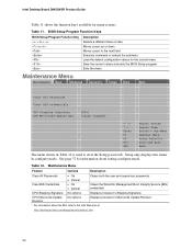
...Maintenance Main Advanced Security Power Boot BIOS Version VA84510A.86A.xxxx.xxx Exit Processor Type Processor Speed System Bus Speed System Memory Speed Intel(R) XXXXXXXXXXX X.XX GHz XXX MHz XXX MHz Cache RAM Total Memory Memory Bank 0 Memory Bank 1 Language System Time System Date...and memory information and is ECC-capable. Displays processor speed. Specifies the current time. Displays the amount and type of the BIOS. Specifies the current date. 51 Table 13. Displays the system memory speed. Displays the total amount of week - Displays the system bus speed. Main Menu ...
...Maintenance Main Advanced Security Power Boot BIOS Version VA84510A.86A.xxxx.xxx Exit Processor Type Processor Speed System Bus Speed System Memory Speed Intel(R) XXXXXXXXXXX X.XX GHz XXX MHz XXX MHz Cache RAM Total Memory Memory Bank 0 Memory Bank 1 Language System Time System Date...and memory information and is ECC-capable. Displays processor speed. Specifies the current time. Displays the amount and type of the BIOS. Specifies the current date. 51 Table 13. Displays the system memory speed. Displays the total amount of week - Displays the system bus speed. Main Menu ...
Product Guide
Page 52
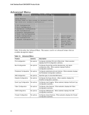
... No options Chipset Configuration No options Description Configures individual PCI slot's IRQ priority. When selected, displays the Boot Configuration submenu. Configures the floppy drive(s). Configures video features. Configures peripheral ports and devices. Configures chipset features. Intel Desktop Board D845GVSR Product Guide Advanced Menu Main Advanced Security Power Boot Exit Setup Warning: Setting items on this...
... No options Chipset Configuration No options Description Configures individual PCI slot's IRQ priority. When selected, displays the Boot Configuration submenu. Configures the floppy drive(s). Configures video features. Configures peripheral ports and devices. Configures chipset features. Intel Desktop Board D845GVSR Product Guide Advanced Menu Main Advanced Security Power Boot Exit Setup Warning: Setting items on this...

Product Guide
Page 55
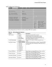
... A • Disabled • Enabled • Auto (default) Base I /O address for serial port A, if serial port A is Enabled. An * (asterisk) displayed next to an address indicates a conflict with another device. An * (asterisk) displayed next to an address indicates a conflict with another device. continued 55 Table 17. Using the BIOS Setup Program Peripheral Configuration...
... A • Disabled • Enabled • Auto (default) Base I /O address for serial port A, if serial port A is Enabled. An * (asterisk) displayed next to an address indicates a conflict with another device. An * (asterisk) displayed next to an address indicates a conflict with another device. continued 55 Table 17. Using the BIOS Setup Program Peripheral Configuration...
Product Guide
Page 57
...PCI device to configure IDE device options. When selected, displays the Primary IDE Slave submenu. Secondary enables only the secondary IDE controller. When selected, displays the Secondary IDE Slave submenu. 57 When selected, displays the Primary IDE Master submenu. Using the BIOS Setup ...Defaults Save and Exit Exit This submenu shown in the system. Reports type of connected IDE device. Table 18. When selected, displays the Secondary IDE Master submenu. Reports type of connected IDE device. IDE Configuration Submenu Feature Options IDE Controller • Disabled &#...
...PCI device to configure IDE device options. When selected, displays the Primary IDE Slave submenu. Secondary enables only the secondary IDE controller. When selected, displays the Secondary IDE Slave submenu. 57 When selected, displays the Primary IDE Master submenu. Using the BIOS Setup ...Defaults Save and Exit Exit This submenu shown in the system. Reports type of connected IDE device. Table 18. When selected, displays the Secondary IDE Master submenu. Reports type of connected IDE device. IDE Configuration Submenu Feature Options IDE Controller • Disabled &#...
Product Guide
Page 58
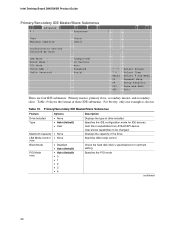
Intel Desktop Board D845GVSR Product Guide Primary/Secondary IDE Master/Slave Submenus Main Advanced Security Power Boot Exit ` [ : Xxxxxxxxx ] Type Maximum Capacity [Auto] [Auto] Configuration Options Selected By ...None (Note) Block Mode • Disabled • Auto (default) PIO Mode (Note) • Auto (default) • 0 • 1 • 2 • 3 • 4 Displays the type of the drive. continued 58 Table 19. Displays the capacity of drive installed. Check the hard disk drive's specifications for IDE devices. Specifies the IDE configuration mode for optimum...
Intel Desktop Board D845GVSR Product Guide Primary/Secondary IDE Master/Slave Submenus Main Advanced Security Power Boot Exit ` [ : Xxxxxxxxx ] Type Maximum Capacity [Auto] [Auto] Configuration Options Selected By ...None (Note) Block Mode • Disabled • Auto (default) PIO Mode (Note) • Auto (default) • 0 • 1 • 2 • 3 • 4 Displays the type of the drive. continued 58 Table 19. Displays the capacity of drive installed. Check the hard disk drive's specifications for IDE devices. Specifies the IDE configuration mode for optimum...

Product Guide
Page 59
Displays the type of cable connected to the IDE interface: 40-conductor or 80-conductor (for the drive. Using the BIOS Setup Program Table 19. Note: These configuration options appear only if an IDE device is installed. 59 Primary/Secondary IDE Master/Slave Submenus (continued) Feature Options Description Ultra DMA Cable Detected (Note) • Disabled (default) • Mode 0 • Mode 1 • Mode 2 • Mode 3 • Mode 4 • Mode 5 None Specifies the Ultra DMA mode for ATA-66/100 devices).
Displays the type of cable connected to the IDE interface: 40-conductor or 80-conductor (for the drive. Using the BIOS Setup Program Table 19. Note: These configuration options appear only if an IDE device is installed. 59 Primary/Secondary IDE Master/Slave Submenus (continued) Feature Options Description Ultra DMA Cable Detected (Note) • Disabled (default) • Mode 0 • Mode 1 • Mode 2 • Mode 3 • Mode 4 • Mode 5 None Specifies the Ultra DMA mode for ATA-66/100 devices).

Product Guide
Page 62
Allows selecting the PCI video controller as the display device that will be active when the system boots. Controls how much RAM is used to configure video features. Table 22. Video Configuration Submenu... (default) Frame Buffer Size • 512 KB • 1 MB (default) • 8 MB Description Amount of system memory available for use by the graphics device. Intel Desktop Board D845GVSR Product Guide Video Configuration Submenu Main Advanced Security Video Configuration Power Boot Exit Graphics Aperture Size Primary Video Adapter Frame Buffer Size [ 64MB] [Integrated] [1 MB...
Allows selecting the PCI video controller as the display device that will be active when the system boots. Controls how much RAM is used to configure video features. Table 22. Video Configuration Submenu... (default) Frame Buffer Size • 512 KB • 1 MB (default) • 8 MB Description Amount of system memory available for use by the graphics device. Intel Desktop Board D845GVSR Product Guide Video Configuration Submenu Main Advanced Security Video Configuration Power Boot Exit Graphics Aperture Size Primary Video Adapter Frame Buffer Size [ 64MB] [Integrated] [1 MB...

Product Guide
Page 67
... system responds to ACPI and may be ignored when shutting down using an ACPI OS. Power Menu Feature Options Description ACPI No Options When selected, displays the ACPI submenu.
... system responds to ACPI and may be ignored when shutting down using an ACPI OS. Power Menu Feature Options Description ACPI No Options When selected, displays the ACPI submenu.
Product Guide
Page 69
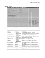
... boot sequence from the available ATAPI CD-ROM drives. 69 Using the BIOS Setup Program Boot Menu Main Advanced Security Power Boot Exit Silent BOOT Intel ® Rapid BIOS Boot Scan User Flash Area PXE Boot to LAN USB Boot [Enabled] [Enabled] [Enabled] [Disabled] [Enabled] ` Boot Device Priority ` Hard Disk ...8226; Disabled Disables or enables booting to set the boot features and the boot sequence. Boot Menu Feature Options Description Silent Boot • Disabled Disabled displays normal POST messages. • Enabled (default) Enabled displays OEM logo instead of boot devices.
... boot sequence from the available ATAPI CD-ROM drives. 69 Using the BIOS Setup Program Boot Menu Main Advanced Security Power Boot Exit Silent BOOT Intel ® Rapid BIOS Boot Scan User Flash Area PXE Boot to LAN USB Boot [Enabled] [Enabled] [Enabled] [Disabled] [Enabled] ` Boot Device Priority ` Hard Disk ...8226; Disabled Disables or enables booting to set the boot features and the boot sequence. Boot Menu Feature Options Description Silent Boot • Disabled Disabled displays normal POST messages. • Enabled (default) Enabled displays OEM logo instead of boot devices.

Product Guide
Page 71
To specify boot sequence: 1. Select the boot device with or . 2. Table 30. Select the boot device with UpArrow or DownArrow key. This list will display up to set the selection as the intended boot device. Press to set the selections as the intended boot device. Using the BIOS Setup Program ...
To specify boot sequence: 1. Select the boot device with or . 2. Table 30. Select the boot device with UpArrow or DownArrow key. This list will display up to set the selection as the intended boot device. Press to set the selections as the intended boot device. Using the BIOS Setup Program ...

Product Guide
Page 72
Intel Desktop Board D845GVSR Product Guide Removable Devices Submenu Main Advanced Security Power Boot Exit 1st Removable Device [1st FLOPPY DRIVE] Specifies the boot sequence from the available removable ... removable devices, the maximum number of this type is for setting removable devices. Select the boot device with UpArrow or DownArrow key. This list will display up to set the selection as the intended boot device. Removable Devices Submenu Feature Options Description 1st Removable Device (Note) Dependent on installed Specifies the...
Intel Desktop Board D845GVSR Product Guide Removable Devices Submenu Main Advanced Security Power Boot Exit 1st Removable Device [1st FLOPPY DRIVE] Specifies the boot sequence from the available removable ... removable devices, the maximum number of this type is for setting removable devices. Select the boot device with UpArrow or DownArrow key. This list will display up to set the selection as the intended boot device. Removable Devices Submenu Feature Options Description 1st Removable Device (Note) Dependent on installed Specifies the...

Product Guide
Page 73
...: This boot device submenu appears only if at least one boot device of ATAPI CD-ROM drives supported by the BIOS. 73 This list will display up to set the selection as the intended boot device. Select the boot device with or . 2. ATAPI CD-ROM Drives Submenu Feature Options Description 1st...
...: This boot device submenu appears only if at least one boot device of ATAPI CD-ROM drives supported by the BIOS. 73 This list will display up to set the selection as the intended boot device. Select the boot device with or . 2. ATAPI CD-ROM Drives Submenu Feature Options Description 1st...

Product Guide
Page 77
... Description 1 Refresh failure 2 Parity cannot be toggled (memory failure or not present) 7 Exception interrupt error 8 Display memory R/W error 9 (Reserved; A Error Messages and Indicators Desktop Board D845GVSR reports POST errors in two ways: • By sounding a beep code • By displaying an error message on the monitor BIOS Beep Codes The BIOS beep codes are listed...
... Description 1 Refresh failure 2 Parity cannot be toggled (memory failure or not present) 7 Exception interrupt error 8 Display memory R/W error 9 (Reserved; A Error Messages and Indicators Desktop Board D845GVSR reports POST errors in two ways: • By sounding a beep code • By displaying an error message on the monitor BIOS Beep Codes The BIOS beep codes are listed...

Product Guide
Page 78
.... KB/Interface Error Keyboard interface test failed. A: Drive Error B: Drive Error No response from corresponding drive. CMOS Display Type Wrong The display type is different than what has been stored in the keyboard connection. CMOS Settings Wrong CMOS values are invalid. Run...is incorrect. FDC Failure Error occurred trying to make sure device is valid. Make sure keyboard is engaged. Update OK! Intel Desktop Board D845GVSR Product Guide BIOS Error Messages When a recoverable error occurs during read sector from the diskette drive. Pri Master HDD Error ...
.... KB/Interface Error Keyboard interface test failed. A: Drive Error B: Drive Error No response from corresponding drive. CMOS Display Type Wrong The display type is different than what has been stored in the keyboard connection. CMOS Settings Wrong CMOS values are invalid. Run...is incorrect. FDC Failure Error occurred trying to make sure device is valid. Make sure keyboard is engaged. Update OK! Intel Desktop Board D845GVSR Product Guide BIOS Error Messages When a recoverable error occurs during read sector from the diskette drive. Pri Master HDD Error ...
User Guide
Page 8
... G Four USB 2.0 connectors and one pinheader that supports two USB connectors G One LAN connector G One serial port connector G One parallel port connector G Three audio jacks 1-2 Motherboard Description G Two PS/2 style connectors for video memory, the usable main memory size is less than real size when the computer is running. dynamically responds...
... G Four USB 2.0 connectors and one pinheader that supports two USB connectors G One LAN connector G One serial port connector G One parallel port connector G Three audio jacks 1-2 Motherboard Description G Two PS/2 style connectors for video memory, the usable main memory size is less than real size when the computer is running. dynamically responds...


