Product Guide
Page 10
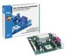
Intel Desktop Board D845GVSR Product Guide ✏ NOTE For information about this Intel desktop board, including the Technical Product Specification (TPS), BIOS updates, and device drivers, go to the Intel World Wide Web site at: http://support.intel.com/support/motherboards/desktop/ Supported Operating Systems The desktop board supports the following operating systems: • Microsoft Windows* 98 SE • Microsoft Windows Me • Microsoft Windows 2000 • Microsoft Windows XP 10
Intel Desktop Board D845GVSR Product Guide ✏ NOTE For information about this Intel desktop board, including the Technical Product Specification (TPS), BIOS updates, and device drivers, go to the Intel World Wide Web site at: http://support.intel.com/support/motherboards/desktop/ Supported Operating Systems The desktop board supports the following operating systems: • Microsoft Windows* 98 SE • Microsoft Windows Me • Microsoft Windows 2000 • Microsoft Windows XP 10

Product Guide
Page 12
Desktop Board Components Item Description A Front panel audio header B Auxiliary line-in header C CD-in (ATAPI) header D 12 V power connector E Rear chassis fan header F Processor socket G Processor ... header Q Chassis intrusion header R BIOS S Front panel header T Front panel USB header U PCI connectors Related Links: Go to the following links for more information about Intel Desktop Board D845GVSR: • http://www.intel.com/design/motherbd • http://support.intel.com/support/motherboards/desktop 12 Intel Desktop Board D845GVSR Product Guide Table 2.
Desktop Board Components Item Description A Front panel audio header B Auxiliary line-in header C CD-in (ATAPI) header D 12 V power connector E Rear chassis fan header F Processor socket G Processor ... header Q Chassis intrusion header R BIOS S Front panel header T Front panel USB header U PCI connectors Related Links: Go to the following links for more information about Intel Desktop Board D845GVSR: • http://www.intel.com/design/motherbd • http://support.intel.com/support/motherboards/desktop 12 Intel Desktop Board D845GVSR Product Guide Table 2.
Product Guide
Page 13
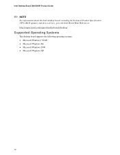
..., or not connecting the additional power supply lead to Desktop Board D845GVSR may be purchased separately. The Intel Pentium 4 processor or Intel Celeron processor may result in damage to the following links or pages for more information about: • Supported Intel processors for Desktop Board D845GVSR http://support.intel.com/support/motherboards/desktop/ • Instructions on installing or upgrading the processor, see...
..., or not connecting the additional power supply lead to Desktop Board D845GVSR may be purchased separately. The Intel Pentium 4 processor or Intel Celeron processor may result in damage to the following links or pages for more information about: • Supported Intel processors for Desktop Board D845GVSR http://support.intel.com/support/motherboards/desktop/ • Instructions on installing or upgrading the processor, see...
Product Guide
Page 14
...links or pages for more information about: • The latest list of tested memory, http://support.intel.com/support/motherboards/desktop/ • SDRAM specifications, http://www.intel.com/technology/memory/pcsdram/spec/ • Installing memory, page 28 in Table 4. The BIOS ... Specification. Table 4. Up to 512 MB utilizing 128 Mb technology - Intel Desktop Board D845GVSR Product Guide Main Memory ✏ NOTE To be fully compliant with all applicable Intel® SDRAM memory specification addendums, the desktop board should be populated with the PC SDRAM specifications.
...links or pages for more information about: • The latest list of tested memory, http://support.intel.com/support/motherboards/desktop/ • SDRAM specifications, http://www.intel.com/technology/memory/pcsdram/spec/ • Installing memory, page 28 in Table 4. The BIOS ... Specification. Table 4. Up to 512 MB utilizing 128 Mb technology - Intel Desktop Board D845GVSR Product Guide Main Memory ✏ NOTE To be fully compliant with all applicable Intel® SDRAM memory specification addendums, the desktop board should be populated with the PC SDRAM specifications.

Product Guide
Page 15
... and utilities, http://support.intel.com/support/motherboards/desktop/ • Installing a front panel audio solution, page 32 in ✏ NOTE The line out connector, located on the back panel, is designed to this output. Auxiliary line in - CD-ROM • Front panel audio connector • Back panel connectors: - Desktop Board Features Intel® 845GV Chipset The...
... and utilities, http://support.intel.com/support/motherboards/desktop/ • Installing a front panel audio solution, page 32 in ✏ NOTE The line out connector, located on the back panel, is designed to this output. Auxiliary line in - CD-ROM • Front panel audio connector • Back panel connectors: - Desktop Board Features Intel® 845GV Chipset The...
Product Guide
Page 16
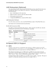
...USB 2.0 ports are built into the RJ-45 LAN connector. USB 1.1 devices will function normally at : http://support.intel.com/support/motherboards/desktop/ RJ-45 LAN Connector LEDs Two LEDs are backward compatible with USB 1.1 devices. four ports routed to the back...established. Hi-Speed USB 2.0 Support ✏ NOTE Computer systems that do not support USB 2.0. 16 Intel Desktop Board D845GVSR Product Guide LAN Subsystem (Optional) The optional Intel 82562ET (with status indicator LEDs • Programmable transit threshold • Configurable EEPROM that meets the ...
...USB 2.0 ports are built into the RJ-45 LAN connector. USB 1.1 devices will function normally at : http://support.intel.com/support/motherboards/desktop/ RJ-45 LAN Connector LEDs Two LEDs are backward compatible with USB 1.1 devices. four ports routed to the back...established. Hi-Speed USB 2.0 Support ✏ NOTE Computer systems that do not support USB 2.0. 16 Intel Desktop Board D845GVSR Product Guide LAN Subsystem (Optional) The optional Intel 82562ET (with status indicator LEDs • Programmable transit threshold • Configurable EEPROM that meets the ...

Product Guide
Page 19
... current necessary to support multiple wake events from the following link: http://support.intel.com/support/motherboards/desktop/ 19 The security feature uses a mechanical switch on the chassis that detects if the chassis cover has been removed. Desktop Board Features Chassis Intrusion The board supports a chassis security feature that can damage the power supply and/or...
... current necessary to support multiple wake events from the following link: http://support.intel.com/support/motherboards/desktop/ 19 The security feature uses a mechanical switch on the chassis that detects if the chassis cover has been removed. Desktop Board Features Chassis Intrusion The board supports a chassis security feature that can damage the power supply and/or...
Product Guide
Page 45
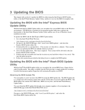
... and the ease-of use of the BIOS by using the Intel Express BIOS Update utility or the Intel® Flash Memory Update Utility, and how to the Intel World Wide Web site: http://support.intel.com/support/motherboards/desktop/ 2. The utility available from a floppy disk or other applications...updates", and select the Express BIOS Update utility file. 3. Your system will automatically update your computer supplier or by navigating to the D845GVSR page on your hard drive. (You can update to complete the BIOS update. Follow the instructions provided in the dialog boxes to a...
... and the ease-of use of the BIOS by using the Intel Express BIOS Update utility or the Intel® Flash Memory Update Utility, and how to the Intel World Wide Web site: http://support.intel.com/support/motherboards/desktop/ 2. The utility available from a floppy disk or other applications...updates", and select the Express BIOS Update utility file. 3. Your system will automatically update your computer supplier or by navigating to the D845GVSR page on your hard drive. (You can update to complete the BIOS update. Follow the instructions provided in the dialog boxes to a...
Product Guide
Page 49
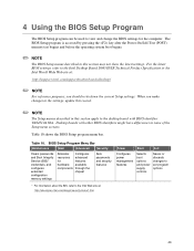
.... 4 Using the BIOS Setup Program The BIOS Setup program can be used to the Intel Desktop Board D845GVSR Technical Product Specification or the Intel World Wide Web site at : http://developer.intel.com/design/security/index1.htm 49 For the latest BIOS settings, refer to view and...to set program options * For information about the BIS, refer to the desktop board with other BIOS identifiers might have differences in this section apply to the Intel Web site at : http://support.intel.com/support/motherboards/desktop/ ✏ NOTE For reference purposes, you make changes to the settings...
.... 4 Using the BIOS Setup Program The BIOS Setup program can be used to the Intel Desktop Board D845GVSR Technical Product Specification or the Intel World Wide Web site at : http://developer.intel.com/design/security/index1.htm 49 For the latest BIOS settings, refer to view and...to set program options * For information about the BIS, refer to the desktop board with other BIOS identifiers might have differences in this section apply to the Intel Web site at : http://support.intel.com/support/motherboards/desktop/ ✏ NOTE For reference purposes, you make changes to the settings...
User Guide
Page 1
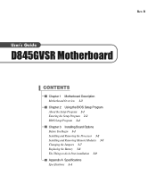
Rev. B User s Guide D845GVSR Motherboard CONTENTS Chapter 1 Motherboard Description Motherboard Overview 1-3 Chapter 2 Using the BIOS Setup Program About the Setup Program 2-1 Entering the Setup Program 2-2 BIOS Setup Program 2-4 Chapter 3 Installing Board Options Before You Begin 3-1 Installing and Removing the Processor 3-2 Installing and Removing Memory Modules 3-5 Changing the Jumpers 3-7 Replacing the Battery 3-8 The Things to do in Post-installation 3-9 Appendix A Specifications Specifications A-1
Rev. B User s Guide D845GVSR Motherboard CONTENTS Chapter 1 Motherboard Description Motherboard Overview 1-3 Chapter 2 Using the BIOS Setup Program About the Setup Program 2-1 Entering the Setup Program 2-2 BIOS Setup Program 2-4 Chapter 3 Installing Board Options Before You Begin 3-1 Installing and Removing the Processor 3-2 Installing and Removing Memory Modules 3-5 Changing the Jumpers 3-7 Replacing the Battery 3-8 The Things to do in Post-installation 3-9 Appendix A Specifications Specifications A-1
User Guide
Page 5
CONTENTS Chapter 1 Chapter 2 Motherboard Description Motherboard Overview 1-3 Rear Panel Connectors 1-4 Using the BIOS Setup Program About the Setup Program 2-1 Entering the Setup Program 2-2 Help Window 2-3 BIOS Setup Program 2-4 Main Menu ...2-4 Advanced Menu 2-5 Security Menu 2-8 Power Menu ...2-10 Boot Menu ...2-10 Exit Menu ...2-12 iii
CONTENTS Chapter 1 Chapter 2 Motherboard Description Motherboard Overview 1-3 Rear Panel Connectors 1-4 Using the BIOS Setup Program About the Setup Program 2-1 Entering the Setup Program 2-2 Help Window 2-3 BIOS Setup Program 2-4 Main Menu ...2-4 Advanced Menu 2-5 Security Menu 2-8 Power Menu ...2-10 Boot Menu ...2-10 Exit Menu ...2-12 iii
User Guide
Page 6
Chapter 3 Installing Board Options Before You Begin 3-1 Installing and Removing the Processor 3-2 Installing the Processor 3-2 Removing the Processor 3-4 Installing and Removing Memory Modules 3-5 Installing a Memory Module 3-6 Removing a Memory Module 3-6 Changing the Jumpers 3-7 Replacing the Battery 3-8 The Things to do in Post-installation 3-9 Appendix A Specifications Specifications ...A-1 iv Motherboard Description
Chapter 3 Installing Board Options Before You Begin 3-1 Installing and Removing the Processor 3-2 Installing the Processor 3-2 Removing the Processor 3-4 Installing and Removing Memory Modules 3-5 Installing a Memory Module 3-6 Removing a Memory Module 3-6 Changing the Jumpers 3-7 Replacing the Battery 3-8 The Things to do in Post-installation 3-9 Appendix A Specifications Specifications ...A-1 iv Motherboard Description
User Guide
Page 7
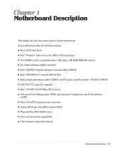
Your motherboard offers the following features: G Micro ATX form factor G Intel® Pentium® 4 processor in the mPGA 478 pin package G Two DIMM sockets, expandable up to 2 GB using 1 GB DDR SDRAM modules G Two built-in Enhanced IDE controllers G Intel® 82845GV Graphics Memory Controller Hub (GMCH) G Intel® 82801DB I/O Controller Hub (ICH4) G Built-in...
Your motherboard offers the following features: G Micro ATX form factor G Intel® Pentium® 4 processor in the mPGA 478 pin package G Two DIMM sockets, expandable up to 2 GB using 1 GB DDR SDRAM modules G Two built-in Enhanced IDE controllers G Intel® 82845GV Graphics Memory Controller Hub (GMCH) G Intel® 82801DB I/O Controller Hub (ICH4) G Built-in...
User Guide
Page 8
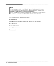
... G Four USB 2.0 connectors and one pinheader that supports two USB connectors G One LAN connector G One serial port connector G One parallel port connector G Three audio jacks 1-2 Motherboard Description dynamically responds to application requirements by allocating the proper amount of display and texturing memory. G Two PS/2 style connectors for video memory, the usable...
... G Four USB 2.0 connectors and one pinheader that supports two USB connectors G One LAN connector G One serial port connector G One parallel port connector G Three audio jacks 1-2 Motherboard Description dynamically responds to application requirements by allocating the proper amount of display and texturing memory. G Two PS/2 style connectors for video memory, the usable...
User Guide
Page 9
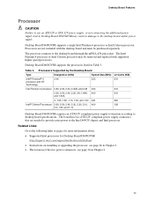
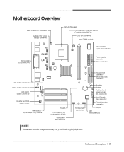
... connector Front Chassis fan connector Chassis intrusion connector Jumper FWH (Firmware Hub) Motherboard Description 1-3 Motherboard Overview Rear chassis fan connector Auxiliary 12V power supply connector mPGA478 socket Intel 82845GV Graphics Memory Controller Hub(GMCH) CPU fan connector DIMM sockets NSC PC87372... connector Front panel audio connector Realtek ALC202A audio codec Intel 82562ET 10/100 Mbps (PLC) device PCI slots Intel 82801DB I/O controller Hub (ICH4) Front panel USB connector Front panel connector NOTE The motherboard's components may vary and look slightly different.
... connector Front Chassis fan connector Chassis intrusion connector Jumper FWH (Firmware Hub) Motherboard Description 1-3 Motherboard Overview Rear chassis fan connector Auxiliary 12V power supply connector mPGA478 socket Intel 82845GV Graphics Memory Controller Hub(GMCH) CPU fan connector DIMM sockets NSC PC87372... connector Front panel audio connector Realtek ALC202A audio codec Intel 82562ET 10/100 Mbps (PLC) device PCI slots Intel 82801DB I/O controller Hub (ICH4) Front panel USB connector Front panel connector NOTE The motherboard's components may vary and look slightly different.
User Guide
Page 10
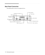
Parallel port connector USB connectors PS/2 mouse connector PS/2 keyboard connector Serial port (COM1) connector Video connector LAN connector Line-in jack Line-out jack Microphone jack USB connectors 1-4 Motherboard Description Rear Panel Connectors The motherboard has connectors for peripheral devices.
Parallel port connector USB connectors PS/2 mouse connector PS/2 keyboard connector Serial port (COM1) connector Video connector LAN connector Line-in jack Line-out jack Microphone jack USB connectors 1-4 Motherboard Description Rear Panel Connectors The motherboard has connectors for peripheral devices.
User Guide
Page 11
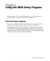
... is stored in a special area of memory called CMOS RAM. The configuration you define through the Setup program is stored in flash memory on the motherboard. Whenever you reboot the computer, it checks the settings, and if it discovers a difference between the information in the CMOS RAM and its actual hardware... the Setup program to change the computer's configuration information and boot-up this memory, so the memory is not erased when you turn on the motherboard backs up sequence, etc.
... is stored in a special area of memory called CMOS RAM. The configuration you define through the Setup program is stored in flash memory on the motherboard. Whenever you reboot the computer, it checks the settings, and if it discovers a difference between the information in the CMOS RAM and its actual hardware... the Setup program to change the computer's configuration information and boot-up this memory, so the memory is not erased when you turn on the motherboard backs up sequence, etc.
User Guide
Page 23
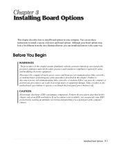
... described in this chapter only at an ESD workstation. If such a station is off. Although your computer. Installing Board Options 3-1 Before You Begin WARNINGS The procedures in this chapter. Some circuitry on the motherboard can continue to disconnect power, telecommunications links, networks, or modems before performing any telecommunications links, networks, or modems...
... described in this chapter only at an ESD workstation. If such a station is off. Although your computer. Installing Board Options 3-1 Before You Begin WARNINGS The procedures in this chapter. Some circuitry on the motherboard can continue to disconnect power, telecommunications links, networks, or modems before performing any telecommunications links, networks, or modems...
User Guide
Page 24
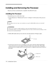
WARNING A processor you plan to install should have a fan type heatsink attached to it to both the processor and motherboard. 2. Pull the ZIF handle sideways away from one described below. Locate the new processor you are completely inserted into the holes of... are installing over the socket so that you install must be aligned with mPGA478 socket. See the illustration in "Motherboard Overview" in Chapter 1 for the location of the socket. 3-2 Installing Board Options Triangle mark Blank corner ZIF handle 3. Installing the Processor To install the processor, follow these steps: 1....
WARNING A processor you plan to install should have a fan type heatsink attached to it to both the processor and motherboard. 2. Pull the ZIF handle sideways away from one described below. Locate the new processor you are completely inserted into the holes of... are installing over the socket so that you install must be aligned with mPGA478 socket. See the illustration in "Motherboard Overview" in Chapter 1 for the location of the socket. 3-2 Installing Board Options Triangle mark Blank corner ZIF handle 3. Installing the Processor To install the processor, follow these steps: 1....
User Guide
Page 25
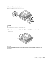
Connect the fan connector cable from the CPU fan to close it. 5. Press the ZIF handle back to the CPU fan connector on the model, the heatsink may burn the chip and void your warranty. Attach the heatsink to the processor socket. NOTE Depending on the motherboard. NOTE If you install the processor chip in the wrong orientation, you may vary. 6. Installing Board Options 3-3 4.
Connect the fan connector cable from the CPU fan to close it. 5. Press the ZIF handle back to the CPU fan connector on the model, the heatsink may burn the chip and void your warranty. Attach the heatsink to the processor socket. NOTE Depending on the motherboard. NOTE If you install the processor chip in the wrong orientation, you may vary. 6. Installing Board Options 3-3 4.


