Product Guide
Page 9
... a 533/400 MHz system bus • Intel® Celeron® processor in an mPGA-478 socket with DIMMs utilizing 512 Mbit technology DRAM devices Intel® 845GV chipset, consisting of Intel® Desktop Board D845GVSR. Table 1. Four ports routed to the back panel - 1 Desktop Board Features Table 1 describes the major features of : • Intel® 82845GV Grahpics and Memory Controller...
... a 533/400 MHz system bus • Intel® Celeron® processor in an mPGA-478 socket with DIMMs utilizing 512 Mbit technology DRAM devices Intel® 845GV chipset, consisting of Intel® Desktop Board D845GVSR. Table 1. Four ports routed to the back panel - 1 Desktop Board Features Table 1 describes the major features of : • Intel® 82845GV Grahpics and Memory Controller...

Product Guide
Page 12
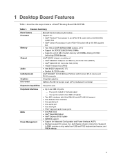
Intel Desktop Board D845GVSR Product Guide Table 2. Desktop Board Components Item Description A Front panel audio header B Auxiliary line-in header C CD-in (ATAPI) header D 12 V power connector E Rear chassis fan header F Processor socket G Processor fan header H DIMM sockets I Main power connector J Diskette drive connector K Secondary IDE ... PCI connectors Related Links: Go to the following links for more information about Intel Desktop Board D845GVSR: • http://www.intel.com/design/motherbd • http://support.intel.com/support/motherboards/desktop 12
Intel Desktop Board D845GVSR Product Guide Table 2. Desktop Board Components Item Description A Front panel audio header B Auxiliary line-in header C CD-in (ATAPI) header D 12 V power connector E Rear chassis fan header F Processor socket G Processor fan header H DIMM sockets I Main power connector J Diskette drive connector K Secondary IDE ... PCI connectors Related Links: Go to the following links for more information about Intel Desktop Board D845GVSR: • http://www.intel.com/design/motherbd • http://support.intel.com/support/motherboards/desktop 12
Product Guide
Page 13
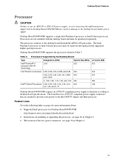
...desktop board through the mPGA-478-pin socket. Processors Supported by the Desktop Board Type Designation (GHz) System Bus (MHz) L2 Cache (KB) Intel® Pentium® 4 processor with supported higher speed processors. The Intel Pentium 4 processor or Intel Celeron processor may result in damage to the desktop board...power to the Intel 845GV chipset and Intel processor. Table 3. Related Links: Go to the following links or pages for more information about: • Supported Intel processors for Desktop Board D845GVSR http://support.intel.com/support/motherboards/desktop/ • ...
...desktop board through the mPGA-478-pin socket. Processors Supported by the Desktop Board Type Designation (GHz) System Bus (MHz) L2 Cache (KB) Intel® Pentium® 4 processor with supported higher speed processors. The Intel Pentium 4 processor or Intel Celeron processor may result in damage to the desktop board...power to the Intel 845GV chipset and Intel processor. Table 3. Related Links: Go to the following links or pages for more information about: • Supported Intel processors for Desktop Board D845GVSR http://support.intel.com/support/motherboards/desktop/ • ...
Product Guide
Page 14
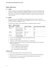
...DDR DIMM sockets with DIMMs that support the Serial Presence Detect (SPD) data structure. Up to 1.0 GB utilizing 256 Mb technology - If your memory modules do not support SPD, you will attempt to this effect on the screen at power up. Intel Desktop Board D845GVSR Product Guide...512 Mb memory technologies for more information about: • The latest list of tested memory, http://support.intel.com/support/motherboards/desktop/ • SDRAM specifications, http://www.intel.com/technology/memory/pcsdram/spec/ • Installing memory, page 28 in Table 4. These include the PC...
...DDR DIMM sockets with DIMMs that support the Serial Presence Detect (SPD) data structure. Up to 1.0 GB utilizing 256 Mb technology - If your memory modules do not support SPD, you will attempt to this effect on the screen at power up. Intel Desktop Board D845GVSR Product Guide...512 Mb memory technologies for more information about: • The latest list of tested memory, http://support.intel.com/support/motherboards/desktop/ • SDRAM specifications, http://www.intel.com/technology/memory/pcsdram/spec/ • Installing memory, page 28 in Table 4. These include the PC...
Product Guide
Page 26
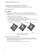
Intel Desktop Board D845GVSR Product Guide Installing and Removing a Processor Instructions on how to install the processor fan heatsink to the integrated processor fan heatsink RM, refer to the Intel World Wide Web site at: http://support.intel.com/support/processors/pentium4/intnotes478.htm 26 Failure to its ... instructions on how to install the processor to the socket (see Figure 2 on page 21. 2. Locate the processor socket and raise the socket lever completely. 3. Lower the lever to do so could damage the processor and the desktop board. the standby power LED should not be lit (...
Intel Desktop Board D845GVSR Product Guide Installing and Removing a Processor Instructions on how to install the processor fan heatsink to the integrated processor fan heatsink RM, refer to the Intel World Wide Web site at: http://support.intel.com/support/processors/pentium4/intnotes478.htm 26 Failure to its ... instructions on how to install the processor to the socket (see Figure 2 on page 21. 2. Locate the processor socket and raise the socket lever completely. 3. Lower the lever to do so could damage the processor and the desktop board. the standby power LED should not be lit (...
Product Guide
Page 28
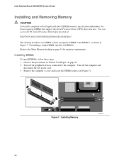
Intel Desktop Board D845GVSR Product Guide Installing and Removing Memory CAUTION To be fully compliant with all peripheral devices connected to the Main Memory heading on page 21. 2. Observe the precautions in "Before You Begin" on page 14 for memory requirements. Turn off all applicable Intel SDRAM memory specification addendums, the board... computer's cover and locate the DIMM sockets (see Figure 7). You can access the PC Serial Presence Detect Specification at: http://www.intel.com/technology/memory/pcsdram/spec/ The desktop board has two DIMM sockets arranged as DIMM 0 and DIMM 1,...
Intel Desktop Board D845GVSR Product Guide Installing and Removing Memory CAUTION To be fully compliant with all peripheral devices connected to the Main Memory heading on page 21. 2. Observe the precautions in "Before You Begin" on page 14 for memory requirements. Turn off all applicable Intel SDRAM memory specification addendums, the board... computer's cover and locate the DIMM sockets (see Figure 7). You can access the PC Serial Presence Detect Specification at: http://www.intel.com/technology/memory/pcsdram/spec/ The desktop board has two DIMM sockets arranged as DIMM 0 and DIMM 1,...

Product Guide
Page 29
...and Replacing Desktop Board Components 4. When the DIMM is inserted, push down on page 21. 2. Turn off all peripheral devices connected to the computer. Gently spread the retaining clips at either end of the DIMM into place. The DIMM pops out of the DIMM with the keys in the socket (see... inset in Figure 7). 6. Hold the DIMM by the edges, lift it away from the computer. 4. Observe the precautions in the bottom edge of the socket. 7. Remove the computer's cover. 5. Reinstall and reconnect any parts you removed or disconnected to the open position. 5. Align the two small notches in...
...and Replacing Desktop Board Components 4. When the DIMM is inserted, push down on page 21. 2. Turn off all peripheral devices connected to the computer. Gently spread the retaining clips at either end of the DIMM into place. The DIMM pops out of the DIMM with the keys in the socket (see... inset in Figure 7). 6. Hold the DIMM by the edges, lift it away from the computer. 4. Observe the precautions in the bottom edge of the socket. 7. Remove the computer's cover. 5. Reinstall and reconnect any parts you removed or disconnected to the open position. 5. Align the two small notches in...

Product Guide
Page 40
... entsprechend. 40 Figure 14 shows the location of the battery. &$87,21 Risk of explosion if the battery is not plugged into a wall socket, the battery has an estimated life of the battery. Bortskaffelse af brugte batterier bør foregå i overensstemmelse med gældende miljø...tyyppi on väärä. Les piles usagées doivent être recyclées dans la mesure du possible. Intel Desktop Board D845GVSR Product Guide Replacing the Battery A coin-cell battery (CR2032) powers the real-time clock and CMOS memory. Replace the battery with 3.3 VSB applied...
... entsprechend. 40 Figure 14 shows the location of the battery. &$87,21 Risk of explosion if the battery is not plugged into a wall socket, the battery has an estimated life of the battery. Bortskaffelse af brugte batterier bør foregå i overensstemmelse med gældende miljø...tyyppi on väärä. Les piles usagées doivent être recyclées dans la mesure du possible. Intel Desktop Board D845GVSR Product Guide Replacing the Battery A coin-cell battery (CR2032) powers the real-time clock and CMOS memory. Replace the battery with 3.3 VSB applied...

User Guide
Page 3
... y a danger d'explosion s'il y a remplacement incorrect de la batterie. i Replace battery only with same type and rating of explosion. Discard used batteries according to an earthed socket outlet. Mettre au rébut les batteries usagées conformément aux instructions du fabricant. Disconnect input power before servicing. Apparatet ma kun...
... y a danger d'explosion s'il y a remplacement incorrect de la batterie. i Replace battery only with same type and rating of explosion. Discard used batteries according to an earthed socket outlet. Mettre au rébut les batteries usagées conformément aux instructions du fabricant. Disconnect input power before servicing. Apparatet ma kun...
User Guide
Page 7
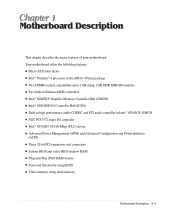
... chapter describes the major features of your motherboard. Your motherboard offers the following features: G Micro ATX form factor G Intel® Pentium® 4 processor in the mPGA 478 pin package G Two DIMM sockets, expandable up to 2 GB using 1 GB DDR SDRAM modules G Two built-in Enhanced IDE controllers G Intel® 82845GV Graphics Memory Controller Hub (GMCH...
... chapter describes the major features of your motherboard. Your motherboard offers the following features: G Micro ATX form factor G Intel® Pentium® 4 processor in the mPGA 478 pin package G Two DIMM sockets, expandable up to 2 GB using 1 GB DDR SDRAM modules G Two built-in Enhanced IDE controllers G Intel® 82845GV Graphics Memory Controller Hub (GMCH...
User Guide
Page 9
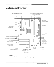
Motherboard Overview Rear chassis fan connector Auxiliary 12V power supply connector mPGA478 socket Intel 82845GV Graphics Memory Controller Hub(GMCH) CPU fan connector DIMM sockets NSC PC87372 super I/O controller Back panel I/O connectors Power supply connector FDD connector CD audio connector Video audio connector Front panel audio connector Realtek ALC202A audio codec Intel 82562ET 10/100 Mbps...
Motherboard Overview Rear chassis fan connector Auxiliary 12V power supply connector mPGA478 socket Intel 82845GV Graphics Memory Controller Hub(GMCH) CPU fan connector DIMM sockets NSC PC87372 super I/O controller Back panel I/O connectors Power supply connector FDD connector CD audio connector Video audio connector Front panel audio connector Realtek ALC202A audio codec Intel 82562ET 10/100 Mbps...
User Guide
Page 24
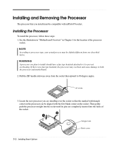
... upward to prevent overheating. If there is no fan type heatsink, the processor may be aligned with mPGA478 socket. See the illustration in "Motherboard Overview" in Chapter 1 for the location of the socket. 3-2 Installing Board Options Triangle mark Blank corner Installing the Processor To install the processor, follow these steps: 1. Locate the new processor...
... upward to prevent overheating. If there is no fan type heatsink, the processor may be aligned with mPGA478 socket. See the illustration in "Motherboard Overview" in Chapter 1 for the location of the socket. 3-2 Installing Board Options Triangle mark Blank corner Installing the Processor To install the processor, follow these steps: 1. Locate the new processor...
User Guide
Page 25
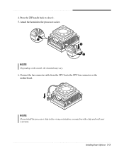
Installing Board Options 3-3 Connect the fan connector cable from the CPU fan to the processor socket. Attach the heatsink to the CPU fan connector on the model, the heatsink may burn the chip and void your warranty. NOTE If you install the processor chip in the wrong orientation, you may vary. 6. 4. Press the ZIF handle back to close it. 5. NOTE Depending on the motherboard.
Installing Board Options 3-3 Connect the fan connector cable from the CPU fan to the processor socket. Attach the heatsink to the CPU fan connector on the model, the heatsink may burn the chip and void your warranty. NOTE If you install the processor chip in the wrong orientation, you may vary. 6. 4. Press the ZIF handle back to close it. 5. NOTE Depending on the motherboard.

User Guide
Page 26
NOTE Depending on the motherboard. Removing the Processor To remove the processor, follow these steps: 1. Unplug the cable connector from the CPU fan connector on the model, the heatsink may vary. 3-4 Installing Board Options CPU fan connector 2. Remove the heatsink by releasing both tabs on the heatsink that secure the heatsink to the socket.
NOTE Depending on the motherboard. Removing the Processor To remove the processor, follow these steps: 1. Unplug the cable connector from the CPU fan connector on the model, the heatsink may vary. 3-4 Installing Board Options CPU fan connector 2. Remove the heatsink by releasing both tabs on the heatsink that secure the heatsink to the socket.

User Guide
Page 27
... Configuration 8 Mbit 64 16 Mbit 64 32 Mbit 64 64 Mbit 64 128 Mbit 64 Installing Board Options 3-5 Press the ZIF handle back to 2 GB. Pull the ZIF handle sideways away from the socket. Each DIMM socket supports the following memory features: G 184-pin 2.5 V DIMM with gold-plated contacts G 200/266/333 MHz... Non-ECC unbuffered DDR SDRAM G Single or double sided DIMM in your computer up from the socket then upward to 90-degree angles and carefully pull the chip straight up to close it. Installing and Removing Memory Modules The...
... Configuration 8 Mbit 64 16 Mbit 64 32 Mbit 64 64 Mbit 64 128 Mbit 64 Installing Board Options 3-5 Press the ZIF handle back to 2 GB. Pull the ZIF handle sideways away from the socket. Each DIMM socket supports the following memory features: G 184-pin 2.5 V DIMM with gold-plated contacts G 200/266/333 MHz... Non-ECC unbuffered DDR SDRAM G Single or double sided DIMM in your computer up from the socket then upward to 90-degree angles and carefully pull the chip straight up to close it. Installing and Removing Memory Modules The...

User Guide
Page 28
... clips outward simultaneously until they snap open. 2. Installing a Memory Module Follow these steps to the socket so the notch in the DIMM connector are aligned with the crossbars in the socket. 3. Release the plastic retaining clips at each end of the DIMM. Press the DIMM straight down... until retaining tabs snap into place around the ends of the socket by pressing the clips outward until the DIMM disengages from the socket and then carefully remove the DIMM from the socket. 3-6 Installing Board Options Orient a DIMM to install DIMMs: 1.
... clips outward simultaneously until they snap open. 2. Installing a Memory Module Follow these steps to the socket so the notch in the DIMM connector are aligned with the crossbars in the socket. 3. Release the plastic retaining clips at each end of the DIMM. Press the DIMM straight down... until retaining tabs snap into place around the ends of the socket by pressing the clips outward until the DIMM disengages from the socket and then carefully remove the DIMM from the socket. 3-6 Installing Board Options Orient a DIMM to install DIMMs: 1.

User Guide
Page 30
...the battery out of three years if the computer is turned off the computer. 2. Insert the new battery with your computer. 3-8 Installing Board Options Replacing the Battery The 3 V, coin-cell CR2032-type battery on the mainboard provides power to your fingers. 5. Replace the system cover.... 7. Disconnect all peripheral devices connected to the computer and then turn off . Battery Battery socket 6. It has an estimated lifetime of its socket with the "+" side as shown below. To replace the battery, follow these steps: 1. Remove the system cover....
...the battery out of three years if the computer is turned off the computer. 2. Insert the new battery with your computer. 3-8 Installing Board Options Replacing the Battery The 3 V, coin-cell CR2032-type battery on the mainboard provides power to your fingers. 5. Replace the system cover.... 7. Disconnect all peripheral devices connected to the computer and then turn off . Battery Battery socket 6. It has an estimated lifetime of its socket with the "+" side as shown below. To replace the battery, follow these steps: 1. Remove the system cover....

User Guide
Page 33
...• Supports AGP 1X/2X/4X data transfers and 2X/4X Fast Writes • Integrated graphics controller (3D/2D graphics) • Power management functions Intel® 82801DB I /O Controller • Floppy drive interface • One multimode parallel port • FIFO serial port • Keyboard and mouse controller ...bus with an integrated 256K L2 cache NOTE The processor depends on the model of computer you purchased. • Two 184-pin 2.5 V DIMM sockets • Each slot supports up to 1 GB memory of 200/266/333 MHz Non-ECC • Unbuffered DDR Synchronous DRAM (DDR SDRAM) ...
...• Supports AGP 1X/2X/4X data transfers and 2X/4X Fast Writes • Integrated graphics controller (3D/2D graphics) • Power management functions Intel® 82801DB I /O Controller • Floppy drive interface • One multimode parallel port • FIFO serial port • Keyboard and mouse controller ...bus with an integrated 256K L2 cache NOTE The processor depends on the model of computer you purchased. • Two 184-pin 2.5 V DIMM sockets • Each slot supports up to 1 GB memory of 200/266/333 MHz Non-ECC • Unbuffered DDR Synchronous DRAM (DDR SDRAM) ...

