Product Guide
Page 3
Contents 1 Desktop Board Features Components...9 Processor ...11 Main Memory ...12 Intel® 845GE Chipset ...12 Intel® 82845GE Graphics and Memory Controller Hub (GMCH 13 Intel® 82801DB I/O Controller Hub (ICH4 13 Firmware Hub (FWH 13 Input/Output (I/O) Controller 13 Graphics Subsystem ......Power Connectors ...19 Fan Connectors ...19 Fan Speed Control (Intel® Precision Cooling Technology 19 Resume on Ring...20 Wake from USB...20 Wake from PS/2 Keyboard/Mouse 20 PME# Wakeup Support 20 Speaker...20 Battery...20 Real-Time Clock...20 2 Installing and Replacing Desktop Board...
Contents 1 Desktop Board Features Components...9 Processor ...11 Main Memory ...12 Intel® 845GE Chipset ...12 Intel® 82845GE Graphics and Memory Controller Hub (GMCH 13 Intel® 82801DB I/O Controller Hub (ICH4 13 Firmware Hub (FWH 13 Input/Output (I/O) Controller 13 Graphics Subsystem ......Power Connectors ...19 Fan Connectors ...19 Fan Speed Control (Intel® Precision Cooling Technology 19 Resume on Ring...20 Wake from USB...20 Wake from PS/2 Keyboard/Mouse 20 PME# Wakeup Support 20 Speaker...20 Battery...20 Real-Time Clock...20 2 Installing and Replacing Desktop Board...
Product Guide
Page 4
Intel Desktop Boards D845GERG2 and D845GEBV2 Product Guide Installing a Processor 24 Installing the Processor Fan Heat Sink 24 Connecting the Processor Fan Heat Sink Cable 25 Removing the Processor ... 30 Connecting the Front Panel Header 31 Installing a Front Panel Audio Solution 31 Installing a Front Panel USB Solution 32 Connecting Fans and Power Cables 33 Connecting Fans ...33 Connecting Power Cables 33 Setting the BIOS Configuration Jumper Block 34 Clearing Passwords ...35 Replacing the Battery ...36 3 Updating the BIOS Updating the BIOS...
Intel Desktop Boards D845GERG2 and D845GEBV2 Product Guide Installing a Processor 24 Installing the Processor Fan Heat Sink 24 Connecting the Processor Fan Heat Sink Cable 25 Removing the Processor ... 30 Connecting the Front Panel Header 31 Installing a Front Panel Audio Solution 31 Installing a Front Panel USB Solution 32 Connecting Fans and Power Cables 33 Connecting Fans ...33 Connecting Power Cables 33 Setting the BIOS Configuration Jumper Block 34 Clearing Passwords ...35 Replacing the Battery ...36 3 Updating the BIOS Updating the BIOS...
Product Guide
Page 5
...Installing a Memory Module 26 9. Front Panel Headers...30 12. Location of Fans and Power Connectors 33 13. Desktop Board D845GERG2 Components 9 2. Removing the AGP or ADD Card 28 10. Desktop Board D845GEBV2 Components 10 3. Location of the BIOS Configuration Jumper Block 34 14. Connecting the...Compliance 75 Chassis and Component Certifications 76 Prevent Power Supply Overload 76 Place Battery Marking 76 Use Only for Intended Applications 76 Figures 1. Location of Standby Power Indicator 18 4. Location of Desktop Board Mounting Holes 23 6. Removing the Battery 38...
...Installing a Memory Module 26 9. Front Panel Headers...30 12. Location of Fans and Power Connectors 33 13. Desktop Board D845GERG2 Components 9 2. Removing the AGP or ADD Card 28 10. Desktop Board D845GEBV2 Components 10 3. Location of the BIOS Configuration Jumper Block 34 14. Connecting the...Compliance 75 Chassis and Component Certifications 76 Prevent Power Supply Overload 76 Place Battery Marking 76 Use Only for Intended Applications 76 Figures 1. Location of Standby Power Indicator 18 4. Location of Desktop Board Mounting Holes 23 6. Removing the Battery 38...
Product Guide
Page 6
... 2. RJ-45 10/100/1000 Gigabit Ethernet LAN Connector LEDs 15 5. Front Panel Header (J9G1 31 6. Peripheral Configuration Submenu 49 17. Power Menu...57 27. EMC Regulations ...73 vi Back Panel Connectors 64 16. Advanced Menu...46 14. Security Menu...56 26. Beep Codes ...69.../Secondary IDE Master/Slave Submenus 52 19. Chipset Configuration Submenu 55 24. Hard Disk Drives Submenu 59 31. Safety Regulations...73 40. Intel Desktop Boards D845GERG2 and D845GEBV2 Product Guide 15. Front Panel USB 2.0 Header (J9F1 32 8. Boot Device Priority Submenu 59 30. ATAPI CD-ROM Drives...
... 2. RJ-45 10/100/1000 Gigabit Ethernet LAN Connector LEDs 15 5. Front Panel Header (J9G1 31 6. Peripheral Configuration Submenu 49 17. Power Menu...57 27. EMC Regulations ...73 vi Back Panel Connectors 64 16. Advanced Menu...46 14. Security Menu...56 26. Beep Codes ...69.../Secondary IDE Master/Slave Submenus 52 19. Chipset Configuration Submenu 55 24. Hard Disk Drives Submenu 59 31. Safety Regulations...73 40. Intel Desktop Boards D845GERG2 and D845GEBV2 Product Guide 15. Front Panel USB 2.0 Header (J9F1 32 8. Boot Device Priority Submenu 59 30. ATAPI CD-ROM Drives...
Product Guide
Page 8
...- One AGP connector - Six PCI bus add-in card connectors - Two ports routed to the Intel World Wide Web site at: http://support.intel.com/support/motherboards/desktop/ 8 Three PCI bus add-in card connectors - One optional Communication and Networking Riser (CNR) ... Desktop Board D845GERG2: - Feature Summary (continued) Peripheral Interfaces • Up to the back panel - One AGP connector One optional CNR connector (slot shared with PCI bus connector 6) BIOS • Intel/AMI BIOS • 4 Mbit symmetrical flash memory • Support for SMBIOS Power ...
...- One AGP connector - Six PCI bus add-in card connectors - Two ports routed to the Intel World Wide Web site at: http://support.intel.com/support/motherboards/desktop/ 8 Three PCI bus add-in card connectors - One optional Communication and Networking Riser (CNR) ... Desktop Board D845GERG2: - Feature Summary (continued) Peripheral Interfaces • Up to the back panel - One AGP connector One optional CNR connector (slot shared with PCI bus connector 6) BIOS • Intel/AMI BIOS • 4 Mbit symmetrical flash memory • Support for SMBIOS Power ...
Product Guide
Page 9
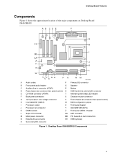
... X Front panel header J Processor fan connector Y Intel 82801DB (ICH4) K DIMM sockets Z Front panel USB 2.0 header L Super I/O controller AA AGP connector M Main power connector BB PCI bus add-in card connectors N Diskette drive connector CC CNR (optional) O Secondary IDE connector Figure 1. Desktop Board Features Components Figure 1 shows the approximate location of the major components on Desktop Board D845GERG2.
... X Front panel header J Processor fan connector Y Intel 82801DB (ICH4) K DIMM sockets Z Front panel USB 2.0 header L Super I/O controller AA AGP connector M Main power connector BB PCI bus add-in card connectors N Diskette drive connector CC CNR (optional) O Secondary IDE connector Figure 1. Desktop Board Features Components Figure 1 shows the approximate location of the major components on Desktop Board D845GERG2.
Product Guide
Page 10
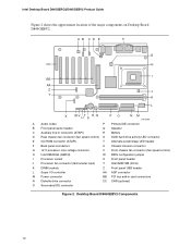
Desktop Board D845GEBV2 Components 10 Intel Desktop Board D845GERG2/D845GEBV2 Product Guide Figure 2 shows the approximate location of the major components on Desktop Board D845GEBV2. A B CD E F G CC H I BB AA Z J Y K L X WV UT S R Q PO NM OM13589 A Audio codec P ...activity LED connector E CD-ROM connector (ATAPI) T Alternate power/sleep LED header F Back panel connectors U Chassis intrusion connector G 12 V processor core voltage connector V Front chassis fan connector (fan speed control) H Intel 82845GE (GMCH) W BIOS configuration jumper I Processor socket X...
Desktop Board D845GEBV2 Components 10 Intel Desktop Board D845GERG2/D845GEBV2 Product Guide Figure 2 shows the approximate location of the major components on Desktop Board D845GEBV2. A B CD E F G CC H I BB AA Z J Y K L X WV UT S R Q PO NM OM13589 A Audio codec P ...activity LED connector E CD-ROM connector (ATAPI) T Alternate power/sleep LED header F Back panel connectors U Chassis intrusion connector G 12 V processor core voltage connector V Front chassis fan connector (fan speed control) H Intel 82845GE (GMCH) W BIOS configuration jumper I Processor socket X...
Product Guide
Page 11
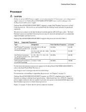
... that are not included with the desktop board and must be removed and replaced to the Intel desktop board through the mPGA478-pin socket. Desktop Board D845GERG2/D845GEBV2 supports a single Intel Pentium 4 processor or Intel Celeron processor. Processors are needed to provide extra power to the Intel World Wide Web site at: http://support.intel.com/support/motherboards/desktop/ For instructions on installing or upgrading...
... that are not included with the desktop board and must be removed and replaced to the Intel desktop board through the mPGA478-pin socket. Desktop Board D845GERG2/D845GEBV2 supports a single Intel Pentium 4 processor or Intel Celeron processor. Processors are needed to provide extra power to the Intel World Wide Web site at: http://support.intel.com/support/motherboards/desktop/ For instructions on installing or upgrading...
Product Guide
Page 12
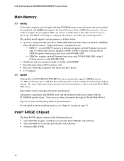
...power up to support DIMMs based on the screen at DDR266 speeds when using a processor with gold-plated contacts. DDR333: to run in non-ECC mode) • 2.5 V memory ✏ NOTE Desktop Board D845GERG2/D845GEBV2 has been designed to 2 GB, but this effect on 512 Mbit technology up . Intel Desktop Board D845GERG2... these Intel desktop boards. Supported memory configuration are: - If your memory modules do not support SPD, you will run DDR333 memory at : http://support.intel.com/support/motherboards/desktop/ All memory components and DIMMs used with the desktop boards must comply...
...power up to support DIMMs based on the screen at DDR266 speeds when using a processor with gold-plated contacts. DDR333: to run in non-ECC mode) • 2.5 V memory ✏ NOTE Desktop Board D845GERG2/D845GEBV2 has been designed to 2 GB, but this effect on 512 Mbit technology up . Intel Desktop Board D845GERG2... these Intel desktop boards. Supported memory configuration are: - If your memory modules do not support SPD, you will run DDR333 memory at : http://support.intel.com/support/motherboards/desktop/ All memory components and DIMMs used with the desktop boards must comply...
Product Guide
Page 13
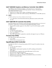
...interfaces in the Intel 845GE chipset platform. ICH4 features on these boards • 1.5 V AGP interface with 4X Side Band Addressing (SBA)/data transfer and 2X and 4X fast write Intel® 82801DB...Three UHCI and one 1.2 MB, 1.44 MB, or 2.88 MB diskette drive • Intelligent power management, including a programmable wake up to six USB ports Firmware Hub (FWH) The 4 Mbit Firmware...8226; Serial IRQ interface compatible with access to the rest of the platform. Features on Desktop Board D845GERG2/D845GEBV2 include: • Single processor support with 533 MHz or 400 MHz data transfer ...
...interfaces in the Intel 845GE chipset platform. ICH4 features on these boards • 1.5 V AGP interface with 4X Side Band Addressing (SBA)/data transfer and 2X and 4X fast write Intel® 82801DB...Three UHCI and one 1.2 MB, 1.44 MB, or 2.88 MB diskette drive • Intelligent power management, including a programmable wake up to six USB ports Firmware Hub (FWH) The 4 Mbit Firmware...8226; Serial IRQ interface compatible with access to the rest of the platform. Features on Desktop Board D845GERG2/D845GEBV2 include: • Single processor support with 533 MHz or 400 MHz data transfer ...
Product Guide
Page 14
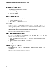
... utilities are connected to power either headphones or amplified speakers only. AD1981B audio codec ✏ NOTE The line out connector, located on Intel's World Wide Web site at: http://support.intel.com/support/motherboards/desktop 14 The LAN subsystem provides the following : • Intel 845GE chipset (AC '97) • Analog Devices Inc. Intel Desktop Board D845GERG2/D845GEBV2 Product Guide Graphics...
... utilities are connected to power either headphones or amplified speakers only. AD1981B audio codec ✏ NOTE The line out connector, located on Intel's World Wide Web site at: http://support.intel.com/support/motherboards/desktop 14 The LAN subsystem provides the following : • Intel 845GE chipset (AC '97) • Analog Devices Inc. Intel Desktop Board D845GERG2/D845GEBV2 Product Guide Graphics...
Product Guide
Page 15
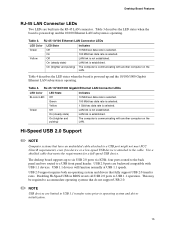
...rates prior to six USB 2.0 ports via ICH4; Disabling Hi-Speed USB in BIOS reverts all USB 2.0 ports to a USB front panel header. Desktop Board Features RJ-45 LAN Connector LEDs Two LEDs are backward compatible with USB 1.1 devices. RJ-45 10/100/1000 Gigabit Ethernet LAN Connector LEDs LED...sec data rate is selected. 100 Mbit/sec data rate is established. LAN link is selected. Table 4 describes the LED states when the board is powered up and the 10/100/1000 Gigabit Ethernet LAN subsystem is not established. The computer is operating. Use a shielded cable that fully support ...
...rates prior to six USB 2.0 ports via ICH4; Disabling Hi-Speed USB in BIOS reverts all USB 2.0 ports to a USB front panel header. Desktop Board Features RJ-45 LAN Connector LEDs Two LEDs are backward compatible with USB 1.1 devices. RJ-45 10/100/1000 Gigabit Ethernet LAN Connector LEDs LED...sec data rate is selected. 100 Mbit/sec data rate is established. LAN link is selected. Table 4 describes the LED states when the board is powered up and the 10/100/1000 Gigabit Ethernet LAN subsystem is not established. The computer is operating. Use a shielded cable that fully support ...
Product Guide
Page 17
... is set , you must enter either password to run the BIOS Setup program after installing an IDE device. Desktop Board Features BIOS The BIOS provides the Power-On Self-Test (POST), the BIOS Setup program, the PCI and IDE auto-configuration utilities, and the video BIOS. You do not ... Setup gives the user restricted access to Setup. • If both passwords are set , pressing at several levels, including: • Advanced Configuration and Power Interface (ACPI) • Suspend to run the BIOS Setup program after you can be set , you install a PCI add-in your computer. If ...
... is set , you must enter either password to run the BIOS Setup program after installing an IDE device. Desktop Board Features BIOS The BIOS provides the Power-On Self-Test (POST), the BIOS Setup program, the PCI and IDE auto-configuration utilities, and the video BIOS. You do not ... Setup gives the user restricted access to Setup. • If both passwords are set , pressing at several levels, including: • Advanced Configuration and Power Interface (ACPI) • Suspend to run the BIOS Setup program after you can be set , you install a PCI add-in your computer. If ...

Product Guide
Page 18
...computer. If the system has a dual-colored power LED on the front panel, the sleep state is standby power to be off . The use of Standby Power Indicator 18 Suspend to its last known awake state. Intel Desktop Board D845GERG2/D845GEBV2 Product Guide ACPI ACPI gives the operating ...system direct control over the power management and Plug & Play functions of delivering...
...computer. If the system has a dual-colored power LED on the front panel, the sleep state is standby power to be off . The use of Standby Power Indicator 18 Suspend to its last known awake state. Intel Desktop Board D845GERG2/D845GEBV2 Product Guide ACPI ACPI gives the operating ...system direct control over the power management and Plug & Play functions of delivering...
Product Guide
Page 19
... multiple wake events from PS/2 keyboard/mouse • PME# wakeup support Power Connectors The desktop board has two power connectors. Fan Connectors The desktop board has two chassis fan connectors (Intel Precision Cooling Technology) and one processor fan connector. Overall system noise reduction will...Wake from the PCI and/or USB buses exceeds power supply capacity, the desktop board may lose register settings stored in the chassis fans always operating at : http://developer.intel.com/design/motherbd/ Hardware Management • Power connectors • Fan connectors • Resume ...
... multiple wake events from PS/2 keyboard/mouse • PME# wakeup support Power Connectors The desktop board has two power connectors. Fan Connectors The desktop board has two chassis fan connectors (Intel Precision Cooling Technology) and one processor fan connector. Overall system noise reduction will...Wake from the PCI and/or USB buses exceeds power supply capacity, the desktop board may lose register settings stored in the chassis fans always operating at : http://developer.intel.com/design/motherbd/ Hardware Management • Power connectors • Fan connectors • Resume ...
Product Guide
Page 20
Intel Desktop Board D845GERG2/D845GEBV2 Product Guide Resume on Ring The operation of Resume on Ring can be unmasked for instructions on the desktop board keeps the clock current when the computer is turned off . PME# Wakeup Support When the PME# signal on the desktop board keeps the values in CMOS RAM and... when the computer is turned off . 20 The speaker provides audible error code (beep code) information during the Power-On Self-Test (POST). Real-Time Clock The desktop board has a time-of a USB peripheral that supports Wake from USB requires the use of -day clock and 100...
Intel Desktop Board D845GERG2/D845GEBV2 Product Guide Resume on Ring The operation of Resume on Ring can be unmasked for instructions on the desktop board keeps the clock current when the computer is turned off . PME# Wakeup Support When the PME# signal on the desktop board keeps the values in CMOS RAM and... when the computer is turned off . 20 The speaker provides audible error code (beep code) information during the Power-On Self-Test (POST). Real-Time Clock The desktop board has a time-of a USB peripheral that supports Wake from USB requires the use of -day clock and 100...
Product Guide
Page 21
...wrist strap and a conductive foam pad. 2 Installing and Replacing Desktop Board Components This chapter tells you how to: • Install the I/O shield • Install and remove the desktop board • Install and remove a processor • Install and ...remove memory • Install and remove an AGP or ADD card • Connect the IDE cable • Connect the front panel header • Install the front panel audio solution • Install the front panel USB solution • Connect fans • Connect power...
...wrist strap and a conductive foam pad. 2 Installing and Replacing Desktop Board Components This chapter tells you how to: • Install the I/O shield • Install and remove the desktop board • Install and remove a processor • Install and ...remove memory • Install and remove an AGP or ADD card • Connect the IDE cable • Connect the front panel header • Install the front panel audio solution • Install the front panel USB solution • Connect fans • Connect power...
Product Guide
Page 23
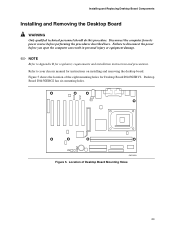
... installation instructions and precautions. Figure 5 shows the location of Desktop Board Mounting Holes 23 Refer to disconnect the power before performing the procedures described here. Failure to your chassis manual for Desktop Board D845GEBV2. Desktop Board D845GERG2 has six mounting holes. Installing and Replacing Desktop Board Components Installing and Removing the Desktop Board WARNING Only qualified technical personnel should do this procedure...
... installation instructions and precautions. Figure 5 shows the location of Desktop Board Mounting Holes 23 Refer to disconnect the power before performing the procedures described here. Failure to your chassis manual for Desktop Board D845GEBV2. Desktop Board D845GERG2 has six mounting holes. Installing and Replacing Desktop Board Components Installing and Removing the Desktop Board WARNING Only qualified technical personnel should do this procedure...
Product Guide
Page 24
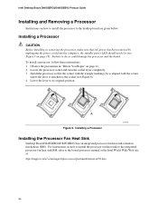
...the lever is attached to the socket (see Figure 3 on page 18). Failure to its original position. Intel Desktop Board D845GERG2/D845GEBV2 Product Guide Installing and Removing a Processor Instructions on how to install the processor to the boxed processor manual or the...Sink Desktop Board D845GERG2/D845GEBV2 has an integrated processor fan heat sink retention mechanism (RM). To install a processor, follow these instructions: 1. mPGA478B mPGA478B mPGA478B A Figure 6. Install the processor so that AC power has been removed by unplugging the power cord from the computer; the standby power ...
...the lever is attached to the socket (see Figure 3 on page 18). Failure to its original position. Intel Desktop Board D845GERG2/D845GEBV2 Product Guide Installing and Removing a Processor Instructions on how to install the processor to the boxed processor manual or the...Sink Desktop Board D845GERG2/D845GEBV2 has an integrated processor fan heat sink retention mechanism (RM). To install a processor, follow these instructions: 1. mPGA478B mPGA478B mPGA478B A Figure 6. Install the processor so that AC power has been removed by unplugging the power cord from the computer; the standby power ...
Product Guide
Page 26
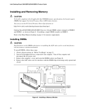
Refer to the Main Memory heading on page 21. 2. Turn off the computer and disconnect the AC power cord. 3. If installing a single DIMM, install it interferes with the memory retention mechanism. Installing DIMMs CAUTION Install memory in "Before You ... avoid interference with the DIMM clips from being easily opened and closed. Remove the AGP video card if it in Figure 8. Figure 8. Intel Desktop Board D845GERG2/D845GEBV2 Product Guide Installing and Removing Memory CAUTION To be fully compliant with all peripheral devices connected to the computer. You can access the...
Refer to the Main Memory heading on page 21. 2. Turn off the computer and disconnect the AC power cord. 3. If installing a single DIMM, install it interferes with the memory retention mechanism. Installing DIMMs CAUTION Install memory in "Before You ... avoid interference with the DIMM clips from being easily opened and closed. Remove the AGP video card if it in Figure 8. Figure 8. Intel Desktop Board D845GERG2/D845GEBV2 Product Guide Installing and Removing Memory CAUTION To be fully compliant with all peripheral devices connected to the computer. You can access the...

